Engineering
Vol.07 No.05(2015), Article ID:56648,12 pages
10.4236/eng.2015.75024
The Low-Frequency Oscillation Restrain Method Research of Converter-Fed Multi-Phase Induction Motor Propulsion system
Haiyan Zeng, Mingzhong Qiao, Peng Zhu
College of Electric Engineering, Naval University of Engineering, Wuhan, China
Email: guicaitang@163. com
Copyright © 2015 by authors and Scientific Research Publishing Inc.
This work is licensed under the Creative Commons Attribution International License (CC BY).
http://creativecommons. org/licenses/by/4. 0/


Received 31 March 2015; accepted 23 May 2015; published 26 May 2015
ABSTRACT
The inverter-fed induction motor drive system may become unstable at low frequencies and light load, and phase current and speed of the induction motor may oscillate periodically, which will threaten safety and reliability of the system. This paper chooses nine-phase induction motor simulated propulsion system as the research object, small disturbance model of three-phase induction motor is built, and average equivalent model of the converter is built by introducing switch function. On the basis above, small disturbance mathematic model of the whole system is obtained. As for the limitation of parameters adjustment method of restrain low-frequency oscillation, the restrain method combining current close-loop with dead-time compensation is put forward. Finally, the proposed restrain method is verified respectively on the built simulation and experimental analogue platform. And the simulation and experimental results indicate that the proposed method can not only satisfy the requirement of low-frequency oscillation restraining, but also be expanded widely, and the stability of the system can get improved greatly.
Keywords:
Induction Motor Propulsion System, Low Frequency Oscillation, Small Disturbance Model, Restrain Method

1. Introduction
For the industrial application of induction motor system powered by inverters, the oscillation phenomenon existed in many low frequency situations. Regular inverter-powered induction motor system usually worked at 50 Hz, and in this situation the oscillation problem could be solved by frequency-skip method. But it is not suitable for electrical propelling in ship, whose propulsion motor is designed to work at low speed and frequency. The low frequency oscillation problem threatened the safety of crew and equipments [1] [2] .
Some papers have studied the reasons of low frequency oscillation. Reference [3] regarded the exchange between filter device and motor magnetic field as the reason, and its author established the small-signal model of inverter-powered induction motor and analyzed the influence from motor and filter parameters to system stability. And on the basis of this method, many other references studied the oscillation problem in various aspects [4] -[9] . But until now the researchers around the world do not make an agreement on the oscillation problem.
Although the reason of low frequency oscillation is not clear until now, researchers still work out some methods to restrain this problem. Just as said in reference [10] , the method of regulating stator frequency is used, and when the motor speeds up, input frequency and power are all decreased and when the motor speeds down, input frequency and power are all increased, and the system oscillation is restrained. The shortage of this method is that the control parameters need to be adjusted constantly. Reference [11] provided a method called “DPWM” regulate strategy, and this method was effective in some occurrence, but could not be applied in all working ranges. In addition, references [11] [12] weakened the oscillation using dead zone compensation method, but it was difficult to restrain the oscillation in a widen speed range.
In this paper, the mathematical model of inverter-induction motor system is established, the small-signal model is analyzed, and the influence from dead zone to system is discussed. In addition, aimed at the characteristic of inverter, the oscillation restrain strategy based on current closed loop and dead zone compensation is presented. At the end of this paper, the strategy given above is verified through simulation and experiment, which suggest the effectiveness and prosperity of this method.
2. Small Signal Model of Induction Motor Powered by Inverter
In this paper, a 9-phase induction motor system is studied, and its system structure is shown in Figure 1. The system consists of rectifier, LC filter, 9-phase inverter and 9-phase induction motor. In Figure 1, DZ1~DZ6 are diodes of 3-phase rectifier unit; Lf and Cf are filter inductance and capacitance on the DC output side; VT1~ VT6 are switches in a 3-phase inverter unit.

Figure 1. Structure of converter-fed nine-phase induction motor variable-frequency driven system.
2.1. Mathematical Model of 9-Phase Induction Motor
The stator winding of 9-phase induction motor is composed by three 3-phase windings, and each 3-phase winding is apart from others with 20 degree. The rotor can be equaled with 3-phase winding. The relationship between stator and rotor winding is shown in Figure 2.
Considering the convenience for analysis, transform matrix is introduced, and the formulation in natural coordinate system is transformed into de-coupling form. Transform matrix in stator side is as follows:
 (1)
(1)
Its backwards matrix is:
 (2)
(2)
which,
 ,
,
 ,
,
 .
.
We can obtain the formulations of induction motor as follows:

Figure 2. Position relationship of nine-phase induction motor between stator and rotor.
1) Flux formulation:
 (3)
(3)
which,
 , ,
, ,
 , ,
, ,
 , , ,
, , ,
 ,
,
 ,
,
 , ,
, ,
 .
.
2) Voltage formulation:
 (4)
(4)
which
 , ,
, ,
 ,
,
 , ,
, ,
 .
.
3) Torque formulation:
 (5)
(5)
2.2. Small Signal Model of Induction Motor
The 9-phase induction motor in this paper can be regarded as three individual 3-phase windings, and through controlling 3-phase winding, the control of 9-phase induction motor can be realized. So it is convenient to start with small-signal model of 3-phase induction motor to analyze the 9-phase motor.
The mathematical model in d-q coordinate system of single 3-phase motor is as follows:
 (6)
(6)
Make the p in formula (6) equal to 0, and we can obtain the following result:
 (7)
(7)
When disturbing signal is applied at stable working point , the system parameters would generate some gain nearby the stable working point
 . So we can obtain formulation (8):
 (8)
(8)
which, Δ means the variable quantity gain at small disturbance.
By solving formulation (9), we can obtain the small disturbance model of single 3-phase induction motor as follow:
 (9)
(9)
which:
 ,
,
 ,
,
 ,
,

2.3. Small Signal Model of Inverter
By introducing switch function, inverter can be equivalent as voltage source or current source circuit, and its mathematical model can be further transformed in d-q coordinate system, which is shown in Figure 3. In the figure above, dd and dq are duty function of inverter switch device in d-q rotating coordinate system.
Suppose the phase voltage of stator winding as is , and it is easy to obtain follow result, namely
 ,
, .
.
From Figure 3, we can obtain the small signal model of inverter as follows:
 (10)
(10)

Figure 3. Average model of three-phase converter.
In which ,
, 
Suppose the DC voltage is constant, namely , and we can get:
 ,
,  ,
, .
.
The small signal model of inverter can be further expressed as:
 (11)
(11)
In actual system, formula (11) can be simplified as follows:
 (12)
(12)
Dead time td need to be set in order to avoid that the two switches in the same bridge of inverter open at the same time. When the switch frequency is pretty high, deviation voltage  could be decomposed and its fundamental component is:
 (13)
(13)
In the rotating system, deviation voltage of inverter caused by dead time effect is:
 (14)
(14)
The dead time can be regarded as cascading a resistance  in stator winding:
 (15)
(15)
2.4. Small Signal Model of Induction Motor System
On the basis above, we can obtain the state formulation of 3-phase unit as follow:
 (16)
(16)


3. Low Frequency Oscillation Restrain of Induction System
Parameter match of motor and inverter is the main reason to cause low frequency oscillation of system. Two kinds of methods are available: 1) adjusting motor parameters (such as stator resistance and inductance) to weaken system oscillation; 2) dead time compensation can be adopted to make the output voltage more ideal. However, the methods above can only weaken the oscillation but cannot eliminate it.
After analyzing lots of low frequency oscillation phenomenon of induction motor system, we can conclude that the characteristic of this phenomenon is the period variation of stator phase current and line-line voltage. Aiming at the characteristics of low frequency oscillation and influence from inverter dead time to system stability, this paper presents the restrain policy, which is based on current closed loop and dead time compensation.
3.1. Dead Time Compensation Based on Current Feed Back
The error voltage expression of 3-phase unit in α-β coordinate system is given in formula (18):
 (17)
(17)
The error voltage vector in α-β coordinate system is shown in Figure 4. The current vector plane is divided into 6 sectors (I~VI), corresponding with 6 output voltage error vector ΔUs (001~110).

Figure 4. Relationship between current polarity and dead-time error voltage.
According to the sector of current vector, output voltage vector is compensated to offset the influence of dead time effect. Table 1 gives the relationship between stator current  and voltage vector (ΔUs) and output error voltage
 .
.
The way to judge sector of current vector is:
 (18)
(18)
From Table 1, we know that in order to get compensation voltage, stator current polarity must be judged correctly. If we judge the current polarity by detecting stator current directly, the error would be quite large. To avoid this risk, this paper provides a new method, which combines the coordinate transformation with low pass filter. Its theory chart is given in Figure 5.
The detected 3-phase unit phase current is transformed into d-q coordinate system to get ids and iqs components, which are filtered to get DC component (idfs and iqfs) of stator current. Then, idfs and iqfs are transformed in natural coordinate system to obtain phase current iafs, ibfs and icfs. In the end, according to filtered current polarity, output voltage is compensated.
3.2. Low Frequency Oscillation Restrain Strategy
Figure 6 is theory picture of low frequency oscillation restrain strategy, which combines closed current loop and dead time compensation. There is no speed loop of rotor in this method, so it is actually a open loop to some degree, but it can be easily realized and has a good effect.
4. Simulation and Experiment
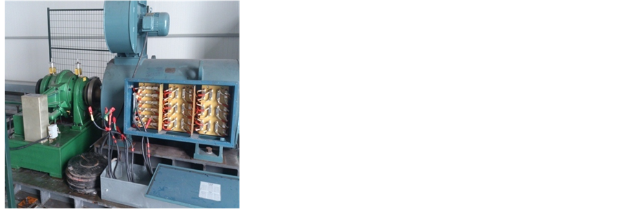
In order to imitate real ship propulsion and verify the effectiveness of restrain strategy proposed above, test platform of electrical ship propulsion system is designed and manufactured, and the test experiment concludes generator unit, 9-phase inverter, 400 kW 9-phase induction motor and power measurement in Figure 7.
Parameters of multi-phase induction motor propulsion system are shown in Table 2.
4.1. Simulation
A 3-phase unit in the 9-phase induction motor system is chosen to be analyzed, and the fundamental frequency is 10 Hz. The system has no load, in which situation it is more likely to oscillate. Figure 8(a) shows the system simulation results with no restrain measure. Figure 8(b) shows the system experiment results with the restrain
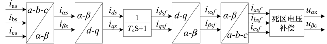
Figure 5. Schematic diagram of current polarity identification.

Table 1. Relationship between current vector and error voltage vector.

Figure 6. Schematic diagram of the restrain method based on current close-loop and dead- time compensated.
Table 2. Parameters of the propulsion system.

 (a) (b)
Figure 7. Experimental platform of nine-phase induction motor propulsion system. (a) 9- phase inverter; (b) 9-phase induction motor and power testing machine.
 (a)
(a)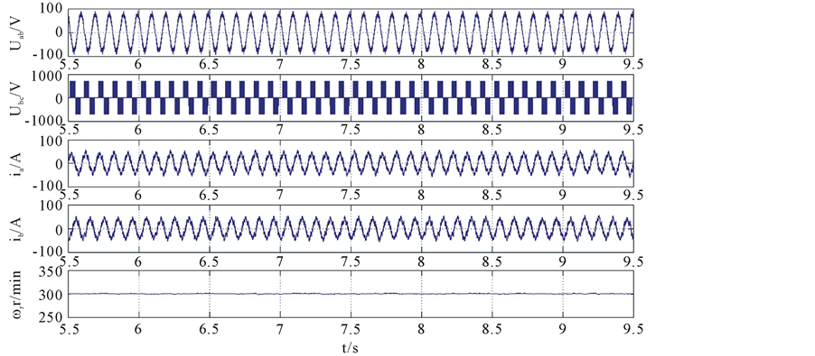 (b)
(b)
Figure 8. Simulation results of induction motor before and after using proposed restrain method at no-load. (a) with no restrain measure; (b) use the restrain measure in this paper.
measure proposed in this paper. From comparison of these two results we can see the effectiveness of the method in this paper.
4.2. Experiment
In order to verify the effectiveness of method in this paper, a single 3-phase unit and the whole 9-phase motor system are both tested.
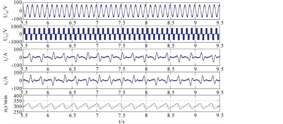
1) A single Y unit system experiment
Figure 9(a) and Figure 9(b) are experiment results of single Y unit system, respectively without oscillation restrain strategy and with restrain strategy. In Figure 8(a), oscillation appears in stator current, line voltage and speed. From Figure 9(b) we can see that there is no oscillation in stator current, voltage and speed after the restrain strategy mentioned above is used, suggesting the effectiveness of this method. In addition, the simulation in Figure 8 coincides with experiment results in Figure 9 very well.
2) Experimental of 9-phase system
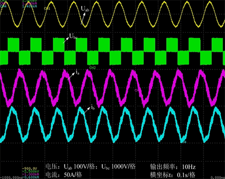
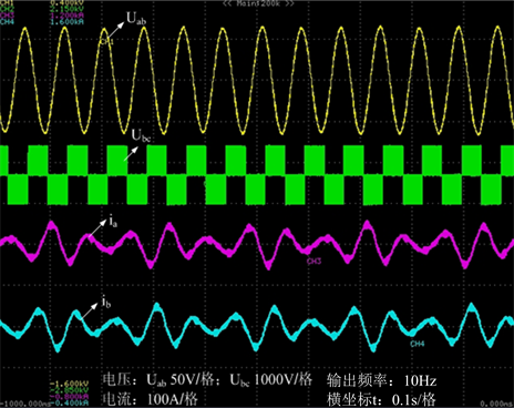
The three 3-phase units are controlled respectively in 3 groups to simulate the 9-phase system. The voltage of group 2 and group 3 lag out 20 and 40 degree of group 1. Experiment results are shown in Figure 10. In Figure 10, the CH1 represents filtered line-line voltage of phase as1 and bs1; CH2 represents line-line voltage of phase cs1
 (a) (b)
Figure 9. Experimental waveforms of single Y-system. (a) with no restrain measure; (b) with restrain measure.

 (a) (b)
Figure 10. Experimental waveforms of 9-phase system. (a) with no restrain measure; (b) with restrain measure.
and bs1; CH3 and CH4 represent current of phase as1 and bs1; CH5 and CH6 represent current of phase as2 and bs2.
From Figure 10, we can see that the low frequency oscillation restrain measure proposed in this paper is effective and can obtain good control performance.
5. Conclusions
Aiming at the problem that oscillation was likely to occur when induction motor system works at a low frequency range, this paper established the small-signal model of induction, and studied how to restrain the oscillation, and obtain some conclusions:
1) Analyzing the average model of induction motor-inverter system, and establishing the small-signal model of the whole motor system;
2) During the low frequency oscillation, the stator current varied in a period. Based on this, the oscillation restrain strategy combining closed current loop with dead time compensation is proposed in this paper. Simulation and experiment results verify the effectiveness of this method.
References
- Singh, G.K. (2002) Multiphase Induction Machine Drive Research―A Survey. Electronic Power System Research, 61, 139-147. http://dx.doi.org/10.1016/S0378-7796(02)00007-X
- Levi, E., Bojoi, R., Profumo, F., et al. (2007) Multiphase Induction Motor Drives―A Technology Status Review. IET Electric Power Applications, 1, 489-516. http://dx.doi.org/10.1049/iet-epa:20060342
- Lipo, T.A. and Krause, P.C. (1969) Stability Analysis of a Rectifier-Inverter Induction Motor Drive. IEEE Transactions on Power Apparatus and Systems, 86, 55-66.
- Nelson, R.H., Lipo, T.A. and Krause, P.C. (1969) Stability Analysis of a Symmertrical Induction Machine. IEEE Transactions on Power Apparatus and Systems, 86, 1710-1717.
- Koga, K., Ueda, R. and Sonoda, T. (1988) Stability Problem in Induction Motor Drive System. Conference Record of the 1988 IEEE Industry Application Society Annual Meeting, 1, 129-136.
- Ueda, R., Sonoda, T., Koga, K., et al. (1992) Stability Analysis in Induction Motor Driven by V/f Controlled General-Purpose Inverter. IEEE Transactions on Industry Application, 28, 472-481.
- Ueda, R., Sonoda, T. and Koga, K. (1989) Experimental Results and Their Simplified Analysis on Instability Problem in PWM Inverter Induction Motor Drives. IEEE Transactions on Industry Application, 25, 86-95.
- Lockwood, M. (1988) Simulation of Unstable Oscillation in PWM Variable-Speed Drives. IEEE Transactions on Industry Application, 1, 137-141.
- Li, H.M., Li, Z.J. and Liu, L.C. (2000) Analysis Low Frequency Oscillation of Inverter Fed Asynchronous Motor. Transaction of China Electro-technical Society, 15, 18-19.
- Guo, Y.J., Wang, Z., Liu, D.Z., et al. (2010) Mathematical Deduction and Stability Analysis of Inverter-Fed Three- Phase Induction Motor Drive Systems. Transaction of China Electro-technical Society, 25, 47-55.
- Colly, R.S., Simlot, A.K. and Hallouda, M.A. (1990) Simplified Model and Corrective Measures for Induction Motor Instability Caused by PWM Inverter Blanking Time. 21st Annual IEEE Power Electronics Specialists Conference PESC’ 90 Record, 1, 678-683.
- Cade, M. (2002) Improvement of Induction Machine Stability by Modulation Techniques. IEE Proceedings of Electric Power Applications, 141, 347-352.