Engineering
Vol. 5 No. 4 (2013) , Article ID: 30548 , 7 pages DOI:10.4236/eng.2013.54050
Effect of Surface Texturing on Lubricating Condition under Point Contact Using Numerical Analysis
1Department of Intelligent Mechanical Systems Engineering, Kagawa University, Takamatsu, Japan
2Graduate School of Engineering, Kagawa University, Takamatsu, Kagawa, Japan
Email: ohue@eng.kagawa-u.ac.jp
Copyright © 2013 Yuji Ohue, Hideki Tanaka. This is an open access article distributed under the Creative Commons Attribution License, which permits unrestricted use, distribution, and reproduction in any medium, provided the original work is properly cited.
Received March 5, 2013; revised April 5, 2013; accepted April 12, 2013
Keywords: Lubricating; Surface Texturing; Point Contact; Dimple; Minimum Oil Film Thickness
ABSTRACT
The contact fatigue life of machine elements is affected by pitting, wear and so on, under heavier loading conditions. Increasing the fatigue life requires mainly the improvements of lubricating condition, operating condition and materials. In order to improve the lubricating condition, it is necessary to investigate the relation of the microscopic surface texturing and the contact modes of machine elements. In this paper, thus, the pressure and oil film thickness of the contact between sphere and the plate with 5 kinds surface texturing were calculated using a commercial software based on Reynolds equation. There was sufficient evidence to suggest that the dimple shape was the optimum texturing to increase the lubricating condition.
1. Introduction
The contact fatigue life of machine elements is affected by pitting, wear and so on, under heavier loading conditions. Increasing the fatigue life requires the improvements of lubricating condition, materials and surface treatment. Surface texturing has been successfully used in many applications to improve the performance of surfaces. One of the most successful applications in engineering is the improvement of tribological performance. Recent advances in smart surface engineering, coating technologies and cold spray technologies offer unique possibilities for better controlling friction and wear under lubricated rolling, sliding or rotating contact conditions [1].
For the hydrodynamic pressure generated between parallel sliding surfaces, several contributing factors were summarized [2]. Surface roughness is recognized as an important role and this discovery has brought about the method of surface texturing for improving the anti-seizure ability of mechanical seals and sliding bearings. Two kinds of lubrication effect of surface texturing have been theoretically discussed in past researches. One is the hydrodynamic effect. As the flow approaches the asperity, the pressure increases. As a result, additional load-carrying capacity is generated. Another is known as secondary lubrication effect, which acts in the regime of mixed lubrication. The fluid trapped in the low region of the texture can be considered as a secondary source of lubricant, which is drawn up by the relative movement to permeate the surface and to reduce the friction and retard seizing. Along with the developments of new techniques, both the design and processing methods of surface texturing have recently been advanced. Smart surface technologies such as reactive ion etching (RIE) using a photo mask [3,4], laser texturing and/or dimpling, laser glazing [5-8] and shot-peening [9] have also become very popular in recent years. In particular, RIE and laser texturing have opened up new possibilities for surface texturing of the lubrication regimes in classical Stribeck diagrams. Controlling dimple size, shape, orientation, and density, researchers were able to modify both the width and the height of the boundary lubrication regimes and thus achieve lower friction and wear at sliding and rotating contact interfaces.
Observations of the surface texturing of some engineering surfaces have suggested that systematic patterning could lead to optimized behavior, as a logical development of the more random texturing achieved through the above processes. Different mechanisms may contribute towards better tribological performance under dry sliding conditions, the main effect is the removal of wear debris from the contact, while in lubricated sliding, in addition to the removal of wear debris, surface textures can also influence lubrication mechanisms, leading to beneficial changes in friction and wear. Surface texturing, which is one of the important factors on the influence of the lubricating condition, is proposed to improvement of tribological performance by many papers. Adachi et al. [10] evaluated the effects of surface texture on the property of water-lubricated SiC by experiment. Haiwu et al. [11] investigated the effects of the shape and the orientation of the surface texture imparted to the hydrodynamic pressure. Also Nanbu et al. [12] evaluated the effects of texture bottom shape and surface relative motion on lubrication enhancement. These studies are experiments and analysis in surface contact between the sliding plates. However, most of machine elements have the point contacts such as ball bearings and gears. In this paper, therefore, the analysis model which consisted of sphere and plate with texturing was prepared, in order to calculate the lubricating condition of the point contact. The guideline of the optimum surface texturing for point contact was proposed.
2. Models and Analysis for Lubricating Calculation
The oil film thickness and the pressure of the contact between a sphere and plates with several texturing were calculated using a commercial software based on Reynolds equation [13]. Figure 1 shows the coordinate system of the point contact for the analysis and 5 kinds of the plates with and without texturing used for the calculation. The basic model is a point contact between a smooth sphere and a plate. The origin was defined as the center at the contact between two solids. The x-axis is defined as the direction of the oil flow. The contact load was applied in the direction of z-axis. The five types of surface texturing were designed. Model 1 is a complete flat. Model 2 is a dimple shape similar to that manufactured by shot peening [9]. Model 3 is a groove shape similar to that machined by grinding in the direction of y-axis. Model 4 and Model 5 are pin-like convex and concavo shapes, respectively. The height from the top to the valley for each model was 1 μm.
Table 1 shows the condition for this calculation. The lower textured plate is fixed. The plate came into contact with the upper sphere with a diameter of  inch
inch  under a normal force F = 500 N. The velocity u of the oil flow was a range of 1 to
  along the direction of x-axis. Kinematic viscosity η of lubricant which is a turbine oil is
  at 313 K. Using Young’s modulus of steel, the Hertzian contact radius a of the point contact was 0.25 mm in this study.
3. Effect of Texturing on Lubricating Condition
Figure 2 shows the contour plots of the pressure and the oil film thickness. The origin of the contact model was defined as the center at the concavo of each texturing. The pressure contour of Model 1 indicated a concentric circular shape and the maximum pressure was almost 3800 MPa. The maximum pressure was almost equal to the value calculated by Hertzian contact theory [14]. When two elastic solids are brought together under a load, a contact area develops, the shape and size of which depend on the applied load, the elastic properties of the materials, and the curvatures of the surfaces. Therefore, the pressure contours of the Models except for Model 1 had the shapes due to the pattern of the plate with each

Figure 1. Surface texturing models.

Table 1. Conditions for lubricating calculation.
texturing. The pressures of both Models 4 and 5 exceeded 5000 MPa, since those texturing patterns were a pin-like convex and concavo. Also, the contours of the oil film thickness were influenced by each texturing. In the calculation condition as shown in Figure 2, the minimum oil film thickness hmin calculated by Model 1 was 0.240 μm and was almost equal to that (hmin = 0.212 mm) of calculated by the equation after Hamrock and Dowson [15].
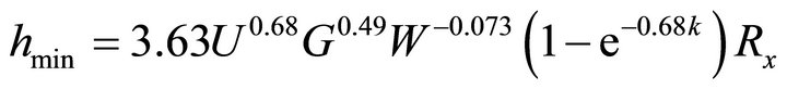 (1)
(1)
where, U is dimensionless speed parameter, G is dimensionless materials parameter, W is dimensionless load parameter, Rx is effective radius in x direction. k is ellipticity parameter and k is equal to 1 since the contact ellipse is a circle in this study.
Figure 3 shows the distributions of the pressure along the x-axis shown in Figure 2. The origin of the contact model for Figure 3 was defined as the center at the concavo of texturing. The pressure along the x-axis for Model 1, which was represented by a broken line, indicated an elliptic distribution. The pressures of Models 4 and 5 fluctuated suddenly at the positions where the concavo of texturing exist. Although the pressure of Models 2 and 3 also fluctuated, each pressure change for Models 2 and 3 was smaller than those of Models 4 and 5. In the case of Model 2, the pressure change fluctuated smoothly and the maximum pressure was smaller comparing with Model 3.
Figure 4 shows the distributions of the oil film thickness along the x-axis shown in Figure 2. The origin of the contact model for Figure 4 was defined as the center at the concavo of texturing. The oil film of Model 1, which was represented by a broken line, was given as a minimum at the outlet of the oil flow in the contact region  . The minimum oil film thickness for each Model, that is Models 3 to 5, became thinner than that for Model 1. In the case of Model 2, the minimum oil film thickness was thicker than that for Model 1. Model 2 which was designed as a dimple shape caused the increase in the oil film thickness.
In Figures 2-4, the pressure and the oil film thickness were calculated under a constant velocity . In order to discuss the oil film thickness under several velocities, the oil film thickness was calculated under the velocity from
  to
to  . Figure 5 shows the change in the minimum oil film thickness with the bearing characteristics
  under the velocity from
  to 6 m/s. The value of
  is
is  at
at  . The minimum oil film thickness became thicker as the value of
  increased. The minimum oil film thickness for Model 2 was higher than that for Model 1, and was the thickest in the textured surface models. Model 2 has lower maximum pressure and a better effect to increase the film than the other surface texturing. Therefore, the dimple shape was the optimum shape in the texturing.

Figure 2. Contour plots of pressure and oil film thickness contours for five kinds of surface texturing.
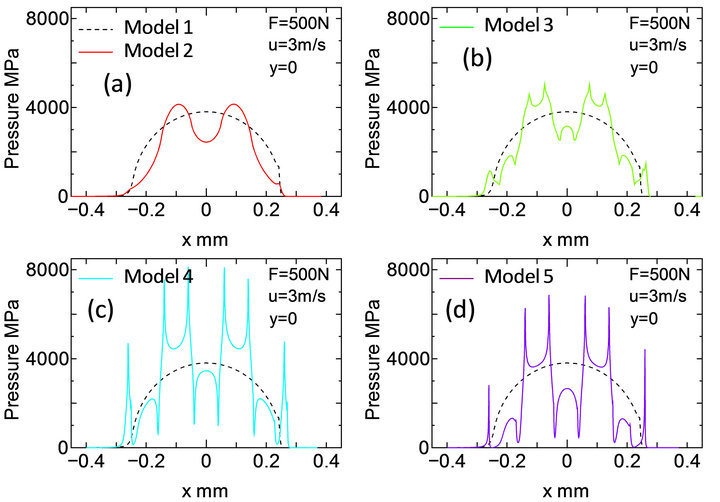
Figure 3. Pressure distributions along x-axis in contact region for five kinds of surface texturing.

Figure 4. Oil film thickness distributions along x-axis in contact region for five kinds of surface texturing.

Figure 5. Relation between bearing characteristic number and minimum oil film thickness.
4. Factor of Improvement in Lubricating Condition for Dimple
As the above mentioned results for calculating the effects of surface texturing on the lubrication in a point contact, the dimple shape (Model 2) which caused better lubrication was the optimum shape for the texturing in this paper. However, the factors brought about the improvement in a lubricating condition are unknown. Therefore, the effect of the dimple arrangement on lubricating condition in a point contact was calculated and was discussed.
4.1. Single, Linear and Planar Models for Lubricating Calculation
Figure 6 shows 3 models changed the arrangement of the
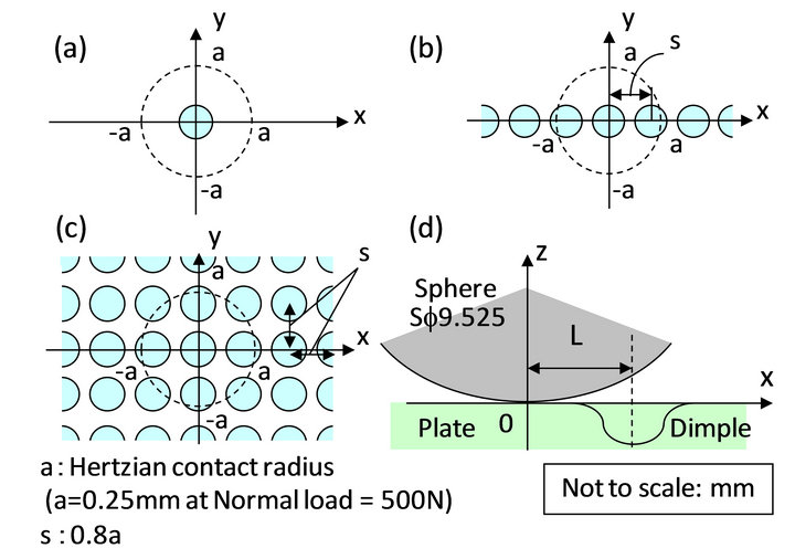
Figure 6. Single, linear and planar dimple models.
dimple on the xy-plane. (a) is a single dimple model denoted by “Single”; (b) is the model aligned periodically dimples with an interval of s = 0.2 mm = 0.8 a along x-axis denoted by “Linear”; (c) is the model arranged periodically dimples with an interval of s on the plate denoted by “Planar”; (d) shows the schematic of the coordinate system for the distance L between the origin of the contact point and an arbitrary dimple. The distance from the origin of the contact between the sphere and the plate to the bottom of the arbitrary dimple was denoted by the symbol L. The positions of the sphere was shifted from  to 1.4a every 0.2a for Single. Because the dimples were arranged periodically at an interval of s=0.8a both of Linear and Planar, lubricating condition was calculated every
  , and the effect of periodic properties in the dimple models on the lubrication was evaluated. In this calculation, the velocity of the oil flow and the normal load were
  and F = 500 N, respectively.
4.2. Effect of Dimple Arrangement to Lubricating Condition
Figure 7 shows the contour plots of the contact pressure for  , and 0.8a. For all cases, the distribution of the pressure was changed as the dimple moved. The maximum pressure among Single, Linear and Planar models was almost the same for each L.
Figure 8 shows the contour plots of the oil film thickness for  and 0.8a. For Single model, the film thickness for
  became thicker than any other L. The film thickness for L except for
  was almost the same. For Linear and Planar models, the film thickness for L = 0.4a became thinner than any other L. The film thickness for
  , 0 and 0.8a was almost the same, and was thicker than that for L = 0.4a. The difference of the model did not bring about the increase in the film thickness, since the maximum value of the film thickness for all models was almost the same.

Figure 7. Contour plots of pressure for three kinds of dimple texturing.
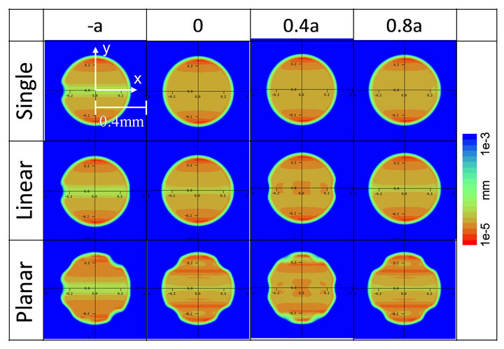
Figure 8. Contour plots of oil film thickness for three kinds of dimple texturing.
Figure 9 shows the distribution of the contact pressure and the oil film thickness along x-axis for L = 0 shown in Figures 7 and 8. For Single model, the single dimple effected the fluctuation of the pressure near the dimple located at x = 0. While, for both Linear and Planar models, the distributed dimples effected the fluctuation of the pressure along x-axis. The distribution of the pressure for both Linear and Planar models was almost the same. However, the maximum pressure for all models was not affected by the model. In the case of the film thickness, though the distributions for both Linear and Planar models were different from that for Single model, the distribution for Linear model was almost equal to that for Planar model. The minimum oil film thickness for all models occurred at x = a, where is the outlet of the oil flow.
In order to discuss the effect of the location of the dimples on the oil film thickness, the minimum oil film thickness with the change in the distance L was investigated. Figure 10 shows the normalized minimum oil film thickness  with the change in the distance L. The minimum oil film thickness for the flat shape

Figure 9. Pressure and oil film thickness distributions along x-axis for three kinds of dimple texturing.
Figure 10. Relation between dimple location and normalized minimum oil film thickness.
(Model 1) shown in Figure 4 and those for Single, Linear and Planar models were denoted by symbols  and
and  , respectively. For Single model, the minimum film thickness at
  was thicker than any other L. The distance
  is corresponded with the inlet of oil flow in the contact region. For Linear and Planar models, the minimum film thickness changed periodically with 0.8a, since the dimples were arranged periodically at an interval of s = 0.8a along x-axis. The minimum film thickness for both Linear and Planar models were similarly affected by the dimple located at the inlet of the oil flow. Furthermore, the dimples located without along x-axis did not strongly affect the minimum oil film thickness, since the minimum oil film thickness for both Linear and Planar models was almost the same change. Therefore, the minimum oil film thickness is totally dependent on the dimple where is located at the inlet of the oil flow in the contact region.
5. Conclusions
In order to calculate the lubricating condition of the point contact, the analysis model which consisted of sphere and plate with texturing was prepared. The guideline of the optimum surface texturing for a point contact was proposed. The obtained results in this paper were summarized as follows:
1) Five kinds of surface texturing were designed, and the contact pressure and the minimum oil film thickness were calculated under a point contact. The dimple shape had a good effect on lubricating condition, from the point of view of both pressure and oil film thickness.
2) In order to investigate the effect of the dimple pattern on the lubricating condition under a point contact, the effect of the dimples arrangement on lubricating condition in a point contact was calculated and was discussed using three kinds of dimple texturing. The dimples located without along x-axis did not strongly affect the minimum oil film thickness, since the minimum oil film thickness for both Linear and Planar models was almost the same change. Therefore, the minimum oil film thickness is totally dependent on the dimple where is located at the inlet of the oil flow in the contact region.
3) Under a point contact, the dimple shape was the optimum shape in the texturing. Designing dimple arranged lineally to moving direction of contact point or oil flow to increase the lubricating condition was important. The dimple texturing may bring about increase of fatigue of life and of wear resistance of machine elements.
6. Acknowledgements
The authors are very grateful to Grants-in-Aid for Scientific Research of JSPS, and Dr. Kunihiko Kakoi, who developed the software on lubricating analysis, for his assistance and encouragement.
REFERENCES
- A. Erdemir, “Review of Engineered Tribological Interfaces for Improved Boundary Lubrication,” Tribology International, Vol. 38, No. 3, 2005, pp. 249-256. doi:10.1016/j.triboint.2004.08.008
- A. O. Lebeck, “Parallel Sliding Load Support in the Mixed Friction Regime, Part 2. Evaluation of the Mechanisms”, Journal of Tribology, Vol. 109, No. 1, 1987, pp. 196-205. doi:10.1115/1.3261319
- X. Wang, K. Kato and K. Adachi, “The Lubrication Effect of Micro-Pits on Parallel Sliding Faces of SiC in Water,” Tribology Transactions, Vol. 45, No. 3, 2002, pp. 294-301. doi:10.1080/10402000208982552
- X. Wang, K. Kato, K. Adachi and K. Aizawa, “Loads Carrying Capacity Map for the Surface Texture Design of SiC Thrust Bearing Sliding in Water,” Tribology International, Vol. 36, No. 3, 2003, pp. 189-197. doi:10.1016/S0301-679X(02)00145-7
- S. Pride, K. Folkert, P. Guichelaar and I. Etsion, “Effect of Micro-Surface Texturing on Breakaway Torque and Blister Formation on Carbon-Graphite Faces in a Mechanical Seal,” Lubrication engineering, Vol. 58, No. 10, 2002, pp. 16-21.
- A. Kovalchenko, O. Ajayi, A. Erdemir, G. Fenske and I. Etsion, “The Effect of Laser Surface Texturing on Transitions in Lubrication Regimes during Unidirectional Sliding Contact,” Tribology International, Vol. 38, No. 3, 2005, pp. 219-225. doi:10.1016/j.triboint.2004.08.004
- A. Kovalchenko, O. Ajayi, A. Erdemir and G. Fenske, “Friction and Wear Behavior of Laser Textured Surface under Lubricated Initial Point Contact,” Wear, Vol. 271, No. 9-10, 2011, pp. 1719-1725.
- G. Dumitru, V. Romano, H. P. Weber, S. Pimenov, T. Kononenko, M. Sentis, J. Hermann and S. Bruneau, “Femtosecond Laser Ablation of Diamond-Like Carbon Films,” Applied Surface Science, Vol. 222, No. 1-4, 2004, pp. 226-233.
- Y. Ohue and Y. Senno, “Effect of Fine Particle Bombarding on Rolling Fatigue Strength of Carburized Steel,” Tribology Online, Vol. 3, No. 2, 2008, pp. 157-162.
- K. Adachi, K. Otsuka, X. Wang and K. Kato, “Effect of Surface Texture on Water Lubrication Properties of Advanced Ceramics,” JSAT Journal, Vol. 50, No. 2, 2006, pp. 107-110.
- Y. Haiwu, X. Wang and F. Zhou, “Geometric Shape Effects of Surface Texture on the Generation of Hydrodynamic Pressure between Conformal Contacting Surfaces,” Tribology Letters, Vol. 37, No. 2, 2010, pp. 123-130. doi:10.1007/s11249-009-9497-4
- T. Nanbu, N. Ren, Y. Yasuda, D. Zhu and Q. J. Wang, “Micro-Textures in Concentrated Conformal-Contact Lubrication: Effects of Texture Bottom Shape and Surface Relative Motion,” Tribology Letters, Vol. 29, No. 3, 2008, pp. 241-252. doi:10.1007/s11249-008-9302-9
- C. H. Venner and A. A. Lubrecht, “Multilevel Methods in Lubrication,” Elsevier Science, 2000.
- K. L. Johnson, “Contact Mechanics,” Cambridge University Press, Cambridge, 1987.
- B. J. Hamrock and D. Dowson, “Ball Bearing Lubrication: The Elastohydrodynamics of Elliptical Contacts,” Wiley, 1981.