Engineering
Vol.4 No.11(2012), Article ID:24529,4 pages DOI:10.4236/eng.2012.411097
Investigation of Soil Aggressiveness towards Underground Fuel Storage Tanks and Water Pipelines in Parts of Bayelsa State, Southern Nigeria
Department of Geology & Physics, Niger Delta University, Amassoma, Nigeria
Email: okenlani@yahoo.com
Received August 6, 2012; revised September 7, 2012; accepted September 30, 2012
Keywords: Soil Corrosivity Potential; Water Pipelines; Soil Aggressivity; Electrical Resistivity; Cathodic Protection
ABSTRACT
Structural failure of buried cast/ductile iron water mains and tanks due to corrosion attacks manifests in leaks and is common in most cities throughout Nigeria. The appropriate corrective action, which aims to restore pipe/tank integrity is usually based on proper understanding of the degree of corrosiveness of the soil. In an attempt to determine the potential corrosiveness of the soil to buried metallic structures in Bayelsa State, surface geoelectrical sounding was carried out. Twenty-five Schlumberger Vertical Electrical Soundings (VES) was carried out in the freshwater and meander belt geomorphic zone and the salt water mangrove swamp and estuary complex of the state using a maximum current electrode separation ranging from 200 - 400 m. The data obtained was interpreted by computer iterative modeling using a 1D inversion technique software (1X1D, Interpex, USA). The results show a high degree of heterogeneity, both laterally and vertically, which is typical of a complex depositional environment. Generally, the sub-soil condition within the expected depth of installation of water mains and storage tanks (0 - 10 m) is slightly or moderately aggressive (effective aggressivity) in the freshwater and meander belt geomorphic zone but is very strongly aggressive in the salt water mangrove swamp and estuary complex. Corrosion cells which may lead to significant corrosion failures may occur in the vicinities of strongly aggressive stations. This poses a significant corrosion risk to metallic water pipes and storage tanks. Current day design should therefore either mandate the use of a non-metallic piping product (water mains) or cathodic protection system. Prediction of potential corrosiveness of a soil and thus the application of proper corrosion control measures will not only protect the environment from spillages but will also avert cost of repair, clean-up and replacement.
1. Introduction
In Nigeria and in most parts of the world, municipal water supply schemes, the oil, gas and chemical industries rely primarily on underground structures to transport and contain their products. These structures include large underground transport pipelines, and storage tanks, both at operating/production sites and at petrol retail stations. These facilities usually generate significant social and economic growth from taxes and creation of tens of thousands of permanent jobs to operate and maintain them. Environmental issues remain a significant concern. Corrosion is one of the main environmental concerns, and is a continually critical issue for the utility boards, petroleum and chemical industries. A vast majority of these underground pipelines and fuel storage tanks are made of carbon steel and coated to prevent corrosion and contamination of the stored product. But these steels have inadequate alloy additions to be considered corrosion resistant, aside, all coatings contain some defects that expose the bare tank/pipe and thus undergo a variety of corrosion failure modes/mechanisms in underground environments, including general corrosion, pitting corrosion, and stress-corrosion cracking (SCC) [1]. Metal loss from internal and external corrosion reduces the service life of a tank or pipe and often results in ruptures. Rupture of underground fuel storage tank/pipe due to corrosion can result in fuel leaks and seepage into the ground with devastating ecological consequences. Given the implications of such ruptures, and the role that corrosion plays in these failures, it is apparent that prediction of potential corrosiveness of a soil and thus the application of proper corrosion control measures will not only protect the environment from spillages but will also avert cost of repair, clean-up and replacement.
The control and effective minimization of corrosion are possible by the proper understanding of the material characteristics and performance as well as the conditions of the environment in which the material will reside. This enhances the design life of steel components and structures in contact with the soil. Aside, it saves money, improves safety and protects the environment. Soil corrosivity is not a measureable parameter. Therefore, in the evaluation of soil corrosivity/aggressivity, a host of critical parameters characteristic of the soil are usually employed. These include soil kind, condition, water content, pH value, redox potentials, microbiological activity, anion and cation levels and electrical resistivity. Soil borings and experimentally measuring these soil properties, traditionally provides the principal source of information for determining soil aggressivity. While the quality of this information is high, it is very localized and may not represent the general soil conditions of the area or may miss some anomalous features. Aside, experimentally measuring these soil properties accurately over a wide area requires considerable laboratory resources, laborious and expensive. [2] reported that the electrical resistivity is highly significant in cases of in-situ determination of the degree of corrosiveness of soils and that it is a main indicator of the corrosiveness of soils, as the rate of corrosion is a function of the electrical conductivity. [3] described the relationship between environmental factors and the corrosive nature of soil, and reported that the soil resistivity has the most profound effect on soil corrosivity.
Evidence concerning a subsurface soil type, its moisture content and aggressivity can be revealed from surface resistivity measurements. Surface geoelectrical method especially the Vertical Electrical Sounding (VES) method of geophysical investigation is a non-invasive, relatively cheap, and a quantitative evaluation technique that can provide data to help diagnose corrosion of buried fuel storage tanks, pipelines and other structures. In addition to being a valuable aid when investigating the severity of corrosive areas, such data is extremely helpful in the later selection of sites for corrosion mitigation measures such as cathodic protection. This paper describes the application of the vertical electrical resistivity (VES) method to determine the electric resistivity variations with lithology and depth with a view to determining the soil aggressivity. The implications of the soil corrosivity variation to corrosion control are examined.
1.1. External Corrosion of Buried Storage Tanks
Corrosion may act on a buried storage tank either internally or externally or both. Furthermore, it may be uniform or nearly uniform in nature or localized in extent and severity (e.g. pitting or crevice corrosion) [4]. External corrosion is a major factor contributing to the deterioration of buried pipes or tanks; it weakens the pipe or tank wall, which increases the risk of failure [4]. Corrosion types that can occur in a buried pipe or tank are: 1) Pitting corrosion owing to material in-homogeneities; 2) Chloride or sulphate induced stress corrosion cracking; 3) Corrosion by concentration cells in soil arising out of differences in oxygen concentration in the soil adjacent to the pipe or tank at different regions; 4) Microbiologically induced corrosion under anaerobic conditions by sulphate-reducing bacteria (SRB) and Acid producing bacteria (APB); 5) Tuberculation because of the buildup of corrosion products on the internal pipe or tank surfaces and 6) Stray current corrosion by earth return direct currents. External corrosion is a function of the interaction between the pipe or tank and the soil that surrounds it.
1.2. Study Area Description
The study area lies between Longitudes 5˚15' and 6˚45' east and Latitudes 4˚15' and 5˚38' north and is located in the coastal area of the transitional environment of the recent Niger Delta (Figure 1). The topography is invariably gentle. Average elevation stands at about 50 m above sea level. The state is within the tropical Equitorial climate dominated by abundant rainfall with an annual mean of ~3000 mm [5]. The delta axis of the state is characterized by intense river meandering and consists of silty clay and sands. The flood plains adjoining the major river network become inundated during the peak of the flood. The mangrove swamp and estuary complexes are surrounded by tidal creeks that are mostly saline. Apart from the main river systems, there are also a series of seasonal streams in the swamps. The area is underlain largely by alluvial and hydromorphic soils and lacustrine sediment of Pleistocene age [6].
2. Materials and Method
Data was acquired in the freshwater and meander belt and salt water mangrove swamp and estuary complex
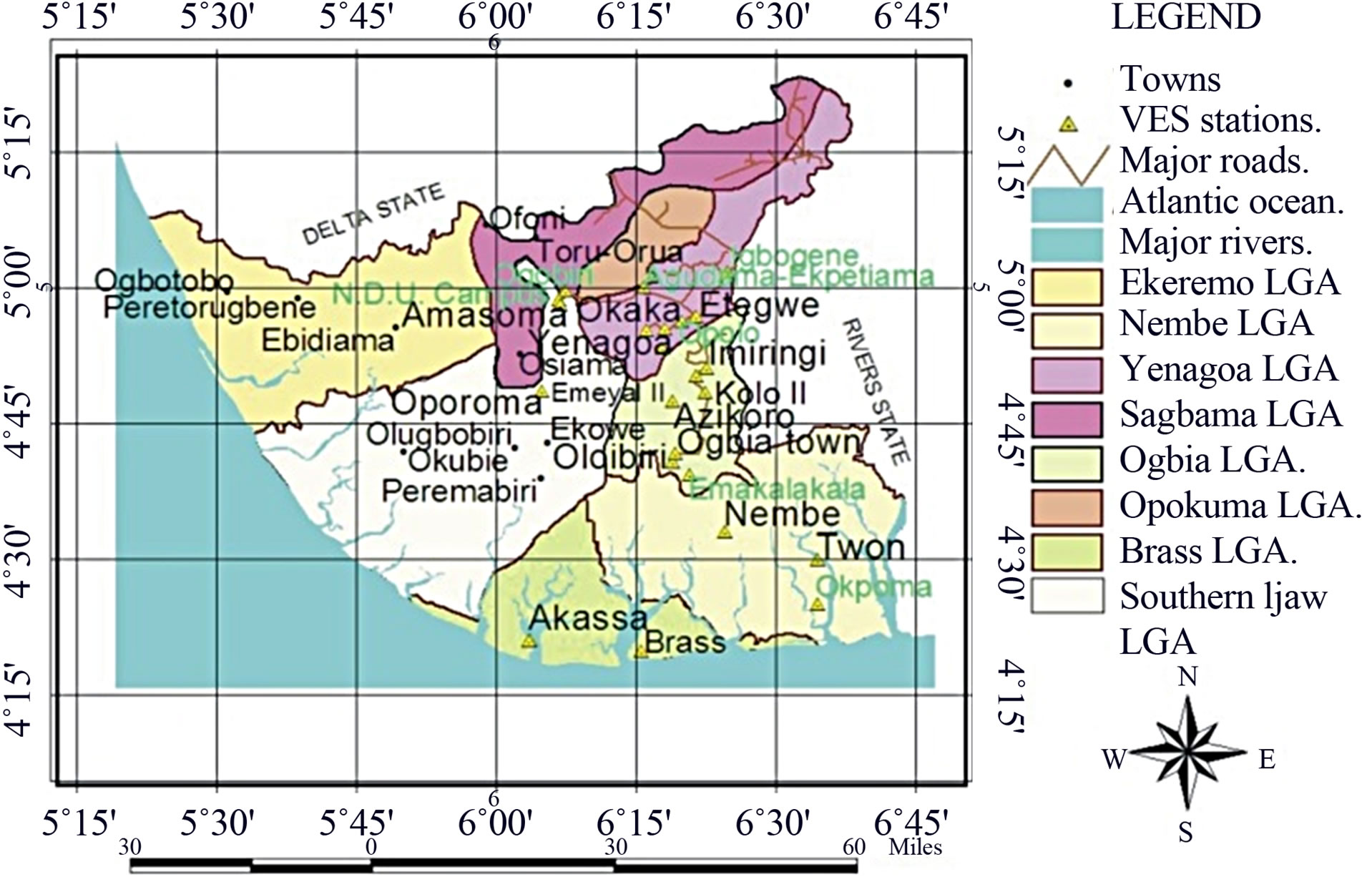
Figure 1. Map of study area showing VES stations.
sub-environments of the state. The area and locations of the sounding stations are shown in Figure 1. The rationale behind the method of sampling is based on the fact that the variation in the spatial distribution of the subsurface resistivity is attributed to a combination of influencing factors such as topography (elevations), water level and water quality, soil type and soil physical property. As a result VES stations were occupied only in communities that are within these two geomorphic sub-environments to assess the soil aggressiveness to buried metal structures.
Nineteen stations were occupied using the Schlumberger configuration in the freshwater and meander belt sub-environment and seven stations were occupied in the delta axis in the salt water mangrove swamp and estuary complex of the state. Communities within the freshwater and meander belt sub-environment data in which was acquired include Yenagoa city, Oloibiri, Ammassoma, Otuoke, etc. while in the salt water mangrove swamp and estuary complex, data was acquired in Nembe town, Akassa, Twon Brass and Okpoma etc. Array spread for the current electrode spacing range between 200 and 400 m. Because the area is marshy, the vertical electrical sounding (VES) data was acquired along existing foot paths or along major roads in the communities. Vertical Electric Sounding using the Schlumberger electrode configuration was carried out by applying current to the ground through two electrodes (A and B) and then measuring the resultant potential difference (∆V) between the potential electrodes (M and N). The center point of the electrode array remains fixed but the spacings of the electrodes are increased so as to obtain information from successively greater depths. In this study, the separation (AB/2) of the current electrodes is as follows: 1.0, 1.5, 2.0, 2.5, 3.2, 4.0, 5.0, 6.0, 7.0, 8.0, 10.0, 12.0, 15.0, 20.0, 25.0, 30.0, 40.0, 50.0, 60.0, 70.0, 80.0, 100.0, 120.0, 150.0, 200.0 while (MN/2) of the potential electrode is as follows: 0.3, 0.5, 1.0, 1.5, 2.5, 5.0, 7.5, 10.0, 15.0, and 25.0. The Schlumberger data are mostly taken in overlapping segments because at each step of AB spacing, the signals of the resistivity meter become weaker. Therefore, MN spacing was enlarged and two values for the same AB/2 were measured, one for the short and one for the long MN spacing. The Schlumberger configuration was employed not only because it is faster and less likely to be influenced by lateral variations but also because it requires a lower number of operators (as only the current electrodes A and B are displaced). Field precautions observed to ensure good VES data quality included firm grounding of the electrodes, and checking for current leakage and creeps to avoid spurious measurements. The instrument used was an Abem Terrameter SAS 3000, a digital self averaging instrument for DC resistivity work. The equipment is rugged, portable, and user friendly and has been proven in many site investigations in Nigeria. A portable 12 V battery was used as the power source while four stainless metal stakes were used as electrodes. The positions and surface elevations of VES sites were also recorded during survey with a GPS receiver.
Data Analysis
The field measurement of resistance (R) was used in the computation of the apparent resistivity ρa given by
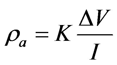 (1)
(1)
where K is the geometrical factor, expressed as
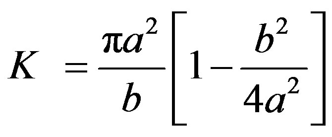 (2)
(2)
where a = half the distance between current electrodes.
b = distance between potential electrodes.
Apparent resistivity values are plotted against the halfcurrent spacing (AB/2) on log-log scale. Guided by the general trend of the field curves, partial curve smoothening of the field curves were made using a software (IPI2win). These plots constitute the field curves. The curves for the different sounding are presented in Figure 2.
The qualitative interpretation of the VES curves was based on the principle that all maxima, minima and point of inflexion are indicators of existence of boundaries of different lithologies. The data obtained was later subjected to computer assisted iterative interpretation using a 1-D inversion technique software (1X1D, Interpex, USA). This programme was used to perform quantitative analysis and interpretation of the field curves. The software requires that the operator introduce the number, thickness, and resistivities of the subsurface layers. The theoretical curve for the initial input parameters is compared with the measured data. The starting model and its corresponding resistivity are transformed, refined or modified by the programme to obtain a best fit relation to the field data. The method of iteration was performed until the fitting error between field data and synthetic model curve became least and constant. Thus, the software yields the number, thickness and resistivity of the various layers. The model parameters for each VES station, as well as the percentage relative root mean square (r.m.s) error which provides quantitative assessment on the quality of the interpretation method are presented in Tables 2 and 3. The prediction of the degree of in-situ aggressiveness from the resistivity measurements was made using the classification shown in Table 1.
3. Results and Discussion
The electrical conductivity of soil surrounding a buried
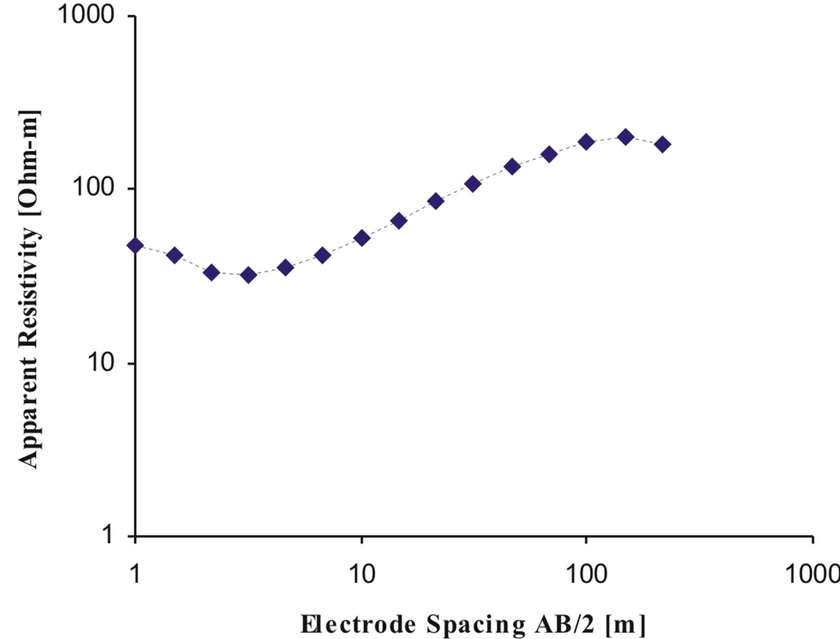
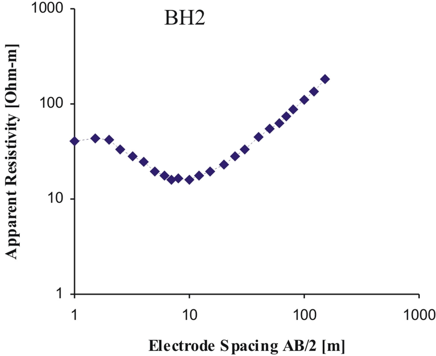
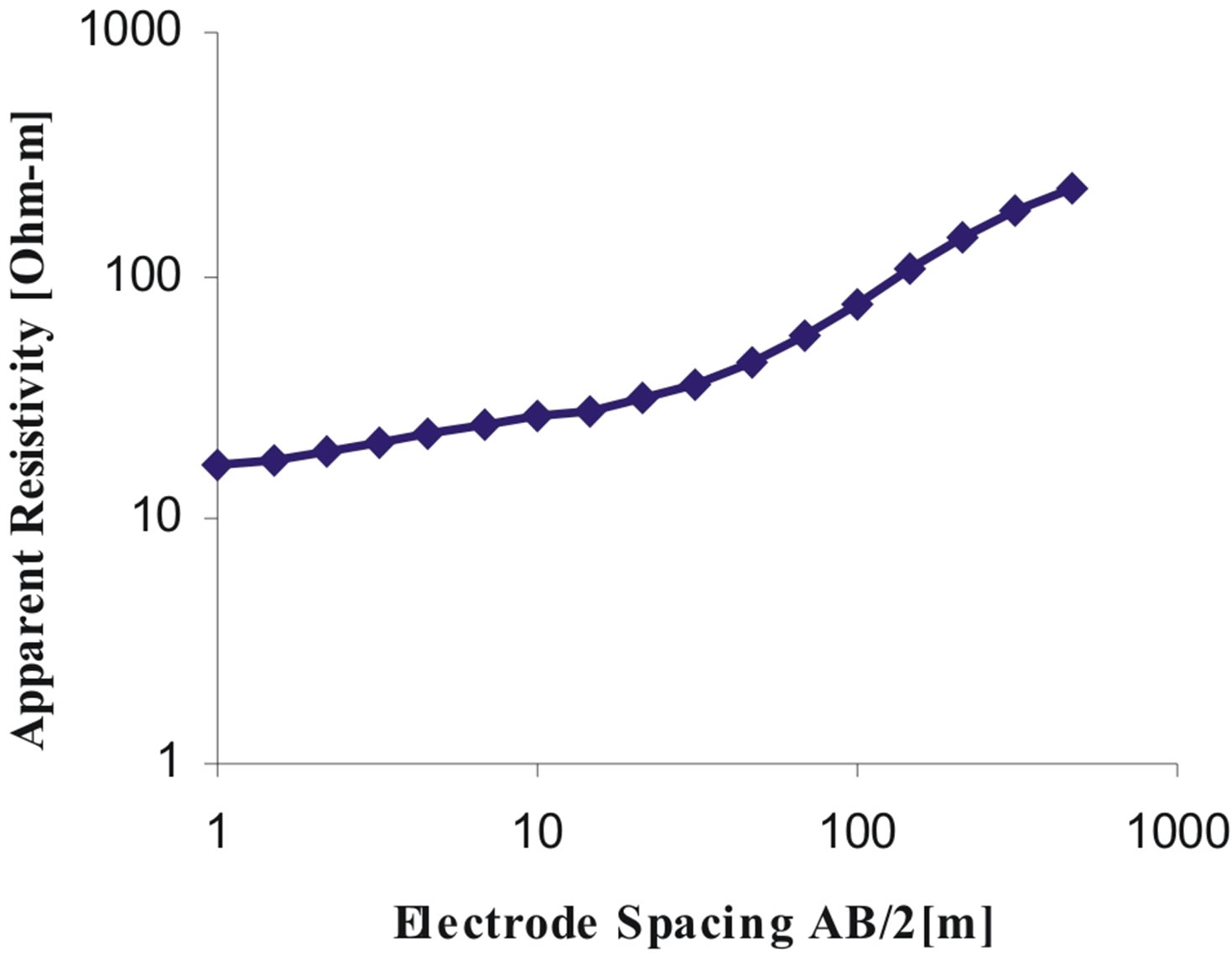
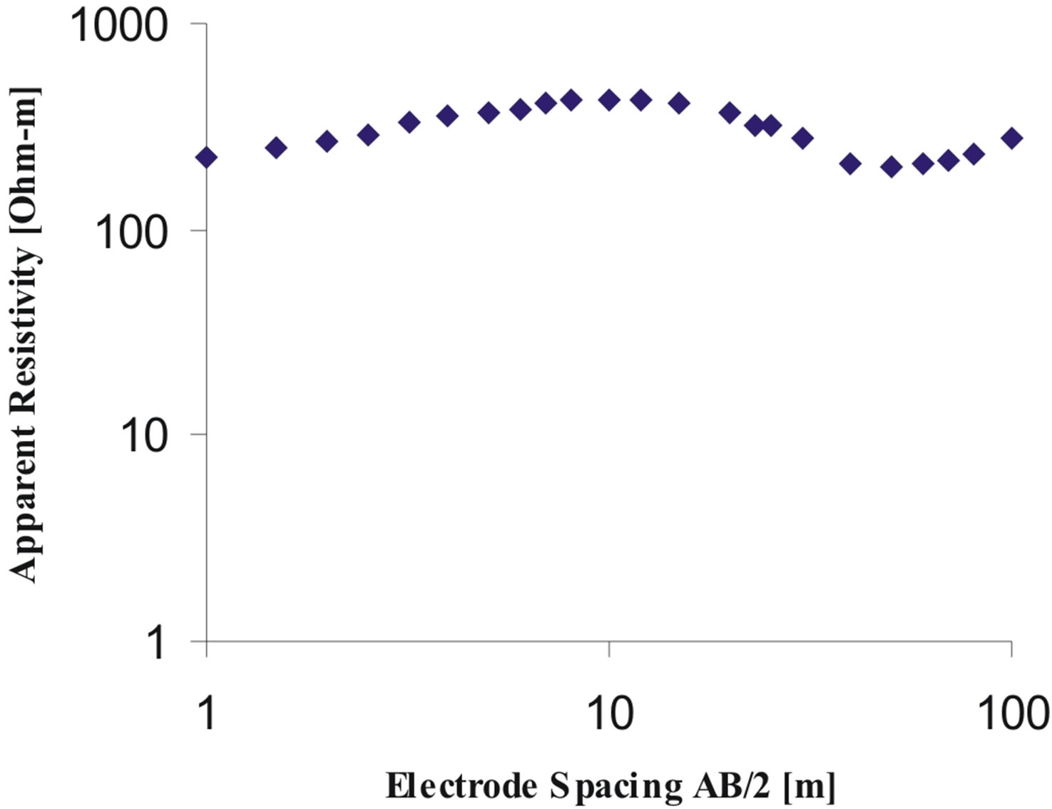
Figure 2. Examples of the obtained electric sounding curves.

Table 1. Classification of soil aggressivity [8].
metallic structure directly influences how corrosive the environment will be to the structure. Corrosion is an electrochemical process that requires a conductive medium to transport current from one point to another on the metal. Corrosion occurs where current discharges from the metal surface. A soil that allows electric current to pass through it easily will promote more severe metal corrosion. Resistivity is a measure of a soil’s ability to conduct electricity. High resistivity inhibits current flow, and low resistivity materials conduct electricity well. Table 1 correlates resistivity values with degree of corrosivity.
Sounding curve types obtained in the area are mostly of the form ρ1 > ρ2 < ρ3 where ρ is density (Figure 2). The results of the interpretative models at the various stations are shown in Tables 2 and 3 respectively. Resistivity values generally range between 4.5 - 14,964 Ωm in the fresh water and meander belt sub-environment but are between 1.9 - 2102.9 Ωm in the salt water mangrove swamp and estuary complex of the state. The results reveal widely irregular variation in resistivity both vertically and laterally (Tables 2 and 3), which is typical of a complex depositional environment. We observed, based on data from this study that in most parts of the State, soil resistivity increases with depth. This is in agreement with the findings of [6]. The variations of the surface-soil resistivity are attributed to local conditions prevailing at the measuring stations. The relatively higher values of resistivity (geoelectric layer 1) indicate dry soils and the presence of coarse sand, and the relatively lower values indicate wet grains of finer sizes and different mineralogical composition, such as fine sands, silts and clays (geoelectric layer 2). The finer the size of the grains, the greater the specific surface area per unit of bulk volume, grain volume, or pore volume, which enables the grains to absorb charged ions at their surfaces and thus the conduction of electric current will be easier [7].
The formation of large corrosion cells which can lead to severe corrosion failures is associated with low resistivities. A low soil resistivity is classified as a highly corrosive soil which is indicative of good electrical conducting path usually due to reduced aeration and excessive electrolytes or wetness in the soil, or mineralization. For resistivities exceeding 180 ohm-m, the medium is fairly well aerated and will not form corrosion cells (Table 1). Water pipes and tanks are usually buried within the depth range of 0 - 10 m in Bayelsa State. The results

Table 2. Electrical resistivity at each station (freshwater and meander belt geomorphic sub-environment).
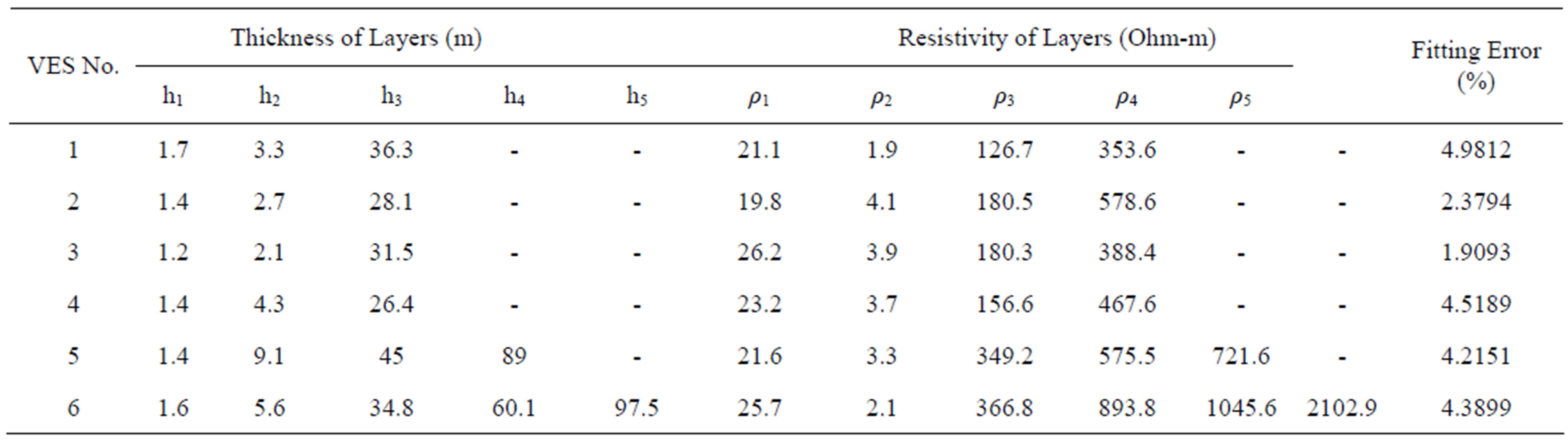
Table 3. Electrical resistivity at each station (salt water mangrove swamp and estuary complex geomorphic sub-environment).
of the VES data show that this depth range is within geoelectric layers 1 and 2 (Tables 2 and 3) respectively. The thickness of geoelectric layer one varies between 0.5 - 2.3 m in the fresh water and meander belt sub-environment. In this layer, sub-soil conditions are generally slightly aggressive or non-aggressive. There are however, anodic regions characterized by low resistivities. These regions are considered to be strongly aggressive or moderately aggressive to buried steel structures. The thickness of the second geoelectric layer varies between 1.9 - 13.0 m. In this layer, there are more anodic regions characterized by low resistivities than in layer 1 (Table 2). These regions are considered to be strongly aggressive or moderately aggressive to buried steel structures and are likely to form severe corrosion cells. About thirteen out of the nineteen measurements are in the moderately aggressive and very strongly aggressive categories representing a significant risk to steel corrosion. Metallic pipes and tanks installed within this layer will have a higher probability of degradation.
Results of data acquired in the salt water mangrove swamp and estuary complex are presented in Table 3. The results show that from the surface to a depth of ~1.7 m (geoelectric layer 1), the soil resistivity ranges between 19 and 26.0 Ωm, but is between 2 and 4.0 Ωm at a depth of ~2.0 - 9.0 m (geoelectric layer 2) in virtually all stations occupied. The sub-soil condition in geoelectric layer 1 is moderately aggressive at all VES stations, but is very strongly aggressive in geoelectric layer 2. We attribute this to peaty soil with high humic acid that results in a high acidity level in the soil, which is rich in organic matter and highly conductive estuarine and saline water rich in chloride [6]. Pipes installed in this zone will have a higher probability of degradation. Comparison of soil resistivity from the freshwater and meander belt geomorphic zone with that from the salt water mangrove and estuary complex reveals a much more aggressive soil condition at the Delta axis than the freshwater and meander belt geomorphic zone at the transitional zone.
Generally, the sub-soil condition within the depth range of 0 - 10 m in Bayelsa state is considered to be slightly or moderately aggressive (effective aggressivity). A key requirement to prevent corrosion and thus ensure a satisfactory performance of a piping system or fuel storage tank is the design and installation of an effective cathodic protection system. The cathodic protection (CP) system is a proven, highly effective and elegant method of corrosion control. Current day design should therefore either mandate the use of a non-metallic piping product (water mains) or cathodic protection system. Each CP system be designed based on corrosivity at a given location. For locations with relatively high soil resistivity, an impressed current CP with a deep-well groundbed system will be necessary. The anode of such CP systems be surrounded by a carbonaceous backfill. The backfill material acts as a sacrificial buffer between the anode and the reaction environment. The backfill particles help to reduce anode resistance to earth, extend anode life by allowing anodic reactions to occur on their surface and provide a porous structure so that the gases produced can escape. Gas entrapment tends to increase the groundbed resistance [4]. Since soil resistivity in the salt water mangrove swamp and estuary complex is low, a shallow groundbed would be cost effective for these low resistivity areas. If soil conditions are unfavourable, shallow horizontal groundbeds are preferred. In this geomorphic zone, because of the low soil resistivity, sacrificial anodes could be used because there will be enough potential to drive the system. It is pertinent to mention that in most parts of the state, soil resistivity increases with depth, and as a result, the lengths of the active zone of the groundbed should increase to minimize the final operating resistance of the system.
4. Conclusions
Surface geoelectrical sounding method was used to determine soil electrical resistivity in an attempt to assess the soil’s potential aggressiveness to buried metallic structures. This method is fast and less expensive compared to the traditional approach of using soil borings and experimentally measuring soil properties to determine soil aggressivity. Generally, the sub-soil condition within the expected depth of installation of water mains and tanks (0 - 10 m) is slightly or moderately aggressive (effective aggressivity) in the freshwater and meander belt geomorphic zone but is very strongly aggressive in the salt water mangrove swamp and estuary complex. Corrosion cells which may lead to significant corrosion failures may occur in the vicinities of strongly aggressive stations particularly in the salt water mangrove swamp and estuary complex. This poses a significant corrosion risk to metallic water pipes and fuel storage tanks.
Current day design should therefore either mandate the use of a non-metallic piping product (water mains) or cathodic protection system. In selecting groundbed sites for cathodic protection, the most important consideration from a design standpoint is determination of effective soil resistivity. Each cathodic protection (CP) system be designed based on corrosivity at a given location. For locations with relatively high soil resistivity, an impressed current CP with a deep-well groundbed system will be necessary. But for locations with low soil resistivity, a sacrificial anode cathodic protection (CP) system can be used. If the soil conditions are unfavourable, shallow horizontal groundbeds would be preferred.
5. Acknowledgements
The authors are grateful to Prof. A. Laogun of the Department of Geology & Physics, Niger Delta University, Wilberforce Island for commenting on the manuscript. The effort of the final year Geophysics students in acquiring the data deserves special appreciation.
REFERENCES
- J. A. Beavers and N. G. Thompson, “External Corrosion of Oil and Natural Gas Pipelines,” American Society of Mechanical Engineers Handbook 13C, Corrosion: Environments and Industries No. 05145, 2006, pp. 1015-1024.
- M. Khare and S. N. Nahar, “Soil Aggressiveness towards Buried Water Pipelines,” Environmental Technology, Vol. 18, No. 2, 1997, pp. 187-194. doi:10.1080/09593331808616526
- W. C. Robinson, “Testing Soil for Corrosiveness,” Materials Performance, Vol. 32, No. 4, 1993, pp. 56-58.
- A. W. Peabody, “Control of Pipeline Corrosion,” NACE, Houston, 1967.
- L. C. Amajor and C. O. Ofoegbu, “Determination of Polluted Aquifers by Stratigraphically Controlled Biochemical Mapping: Example from the Eastern Niger Delta, Nigeria,” In: C. O. Ofoegbu, Ed., Groundwater and Mineral Resources of Nigeria, F. Vieweg, Braunschweig/Wiesbaden, 1997, pp. 62-73.
- M. U. Osakuni and T. K. S. Abam, “Shallow Resistivity Measurement for Cathodic Protection of Pipeline in the Niger Delta,” Environmental Geology, Vol. 45, No. 6, 2004, pp. 747-752. doi:10.1007/s00254-003-0916-9
- H. S. Salem and G. V. Chilingarian, “Determination of Specific Surface Area and Mean Grain Size from well Log-Data and Their Influence on the Physical Behavior of Offshore Reservoir,” Journal of Petroleum Science and Engineering, Vol. 22, No. 4, 1999, pp. 241-252. doi:10.1016/S0920-4105(98)00084-9
- W. V. Baeckmann and W. Schwenk, “Handbook of Cathodic Protection,” Portcullis Press, London, 1975.