Engineering
Vol.5 No.8(2013), Article ID:35548,7 pages DOI:10.4236/eng.2013.58081
Turbulence Modeling Applied to Flow over a Hydraulic Ball Check Valve
Mechanical Engineering, Sami Shamoon College of Engineering, Beer-Sheva, Israel
Email: grinis@sce.ac.il, vit1205@yahoo.com
Copyright © 2013 Leonid Grinis, Vitaly Haslavsky. This is an open access article distributed under the Creative Commons Attribution License, which permits unrestricted use, distribution, and reproduction in any medium, provided the original work is properly cited.
Received July 25, 2012; revised January 7, 2013; accepted January 18, 2013
Keywords: Check-Valve; Vibration; Vortex Shedding
ABSTRACT
This paper describes an experimental, theoretical model, and a numerical study of concentrated vortex flow past a ball in a hydraulic check valve. The phenomenon of the rotation of the ball around the axis of the device, through which liquid flows, has been found. That is, vibration is caused by the rotation of the ball in the check valve. We observe the rotation of the ball around the longitudinal axis of the check valve. This rotation is induced by vortex shedding from the ball. We will discuss computational simulation and experimental investigations of this strong ball rotation. The frequency of the ball vibration and interaction with the check valve wall has been measured as a function of a wide range of Reynolds numbers. The validity of the computational simulation and of the assumptions on which it is based has been proved experimentally. This study demonstrates the possibility of controlling the vibrations in a hydraulic system and proves to be a very effective suppression of the self-excited vibration.
1. Introduction
Internal flows in hydraulic systems have been studied extensively because of their practical applications. Many of these studies, for example, evaluate ball check valves and other devices in hydraulic systems. It is known that the process of fluid flow around a bluff body (such as a sphere or cylinder) is accompanied by a periodic vortex trail (often illustrated by the Karman vortex street) [1-3]. These vortex trails can induce vibrations, with the resulting forces acting on the bluff body in a direction transverse to that of the flow. The growth and movement of these vortices creates a fluctuating lift and drag force on the body [3,4]. It is known that flow in hydraulic devices is related to turbulence and that it sets up chaotic vibration [2-4]. There is a growing body of evidence that an understanding of exploitation of vibration may be desirable or beneficial for the operation of some hydromechanical systems.
Understanding and subsequent exploitation or avoidance of fluid turbulence is one of the major problems in many fields.
We reveal the phenomenon of the vibration and rotation of the ball around the axis of the inner surfaces of the check valve in the flow. This phenomenon was investigated by experimental device and by computational simulation.
Applications of computational fluid dynamics (CFD) to industry continue to grow as this advanced technology takes advantage of the increasing speed of computers. In the last two decades, different areas of flow modeling, including grid generation techniques, solution algorithms, turbulence modeling, and computer hardware capabilities have under gone remarkable growth. In view of these developments, computational fluid dynamics can offer a cost-effective solution to many engineering problems. Various researchers have used turbulence modeling to simulate flow around axisymmetric bodies.
In this study we used ANSYS Fluent (a fluid dynamics computer simulation software product) to model the flow around a ball in a check valve, when the flow is turbulent. Prediction of flows that exhibit substantial separation remains one of the principal challenges of CFD. The main interest of the present study is to calculate the turbulent flow over a ball at high Reynolds numbers.
The nature of the flow around a ball in a valve changes as the Reynolds number of the flow increases, according to [5,6].
The aims of this study were: the experimental investigation of the stability and instability of the vibration of the ball in fluid flow inside a check valve; derivation of a simplified analytical expression for the stability of the vibration motion of the ball rotating in a valve under conditions of fluid flow; validation of the mathematical model and computational simulation versus experimental results; illustration of the possibility to exploit this phenomenon.
2. Experimental Apparatus
A schematic description of the experimental setup is presented in Figure 1(a).
The system consists of the following components:
1) storage tank;
2) centrifugal pump;
3) throttle valve;
4) flow meter;
5) manometer;
6) ball check valve;
7) stroboscope tachometer;
8) manometer;
9) spectrum analyzer vibration meter.
The fluid (in our case, water) was circulated from the storage tank (1) through the ball check valve (6) by the centrifugal pump (2). The flow rate was controlled by the throttle valve (3) and measured by the flow meter (4). The fluid (which was replaced) passed through the gap between the ball’s surface and the wall of the valve.
The frequency of the vibration was measured by a type SR 760 fast Fourier transform (FFT) spectrum analyzer vibration meter (9). A Bruel & Kjaer type 4375 Vacceleration sensor was also used. When we used a valve body made of transparent material, the rotation speed of the ball was also measured by the stroboscope tachometer (7).
The size of the ball in combination with the inner diameter of the valve was examined for certain flow rate values in the following ranges: ball diameter 0.012 m; inner diameter of the valve 0.015 m, and flow rate up to
 (a) (b)
Figure 1. Experimental setup.
1 × 10⁻³ m3/s.
3. Mathematical Model
A schematic description of the device used in this study is given in Figure 1(b). The device, which is essentially spherical in shape, is introduced into a valve through which liquid is flowing.
From experimental analysis of fluid flow around a sphere [7], it is known that vortices form in the wake of the sphere and subsequently break away from it in a periodic process.
This phenomenon is called a “Karman vortex street”. Vortex shedding can produce self-excited oscillations of the ball. This oscillation is characterized by the frequency, which depends on the flow conditions.
Assuming that the distance between the ball and the valve surface is constant, we can regard this ball as a pendulum or rotor of length L and mass m. The point of support of this pendulum or rotor is caused to vibrate with amplitude A0 along the Y axis of the valve, as described in the following equation:
 (1)
(1)
Such a system can be made clear by means of a classic example of a pendulum with a vibrating axis [8]. The movement of the ball can be expressed by the following differential equation:
 (2)
(2)
In the preceding equation,  represents the damping, which is present in all physical systems.
Assuming that
 (3)
(3)
In the preceding equation,  is a slowly varying function of time, and substituting Equation (3) into Equation (2) we obtain differential equation of motion of the system.
The differential equations have been studied by [8,9]. The relation of the ball in a synchronous regime proceeds according to the following equation:
 (4)
(4)
Under steady state conditions, the ball will vibrate and also rotate around the central axis of the valve at an angular velocity, which is given by the following equation:
 (5)
(5)
In the preceding equation, —kinematic viscosity of the water, Re—Reynolds number, and cf, cp, cv—hydrodynamic friction coefficient. This equation was obtained with used solution based on forces and driving moments of balance that act in this system. Substituting Equation (5) into Equation (4), we obtain the condition for stable vibration as well as the rotation of the ball, as a function of the system parameters:
 (6)
(6)
Using the above condition for stability of rotation of the ball in a valve with fluid flow, it is possible to determine the influence of the system parameters on the ball’s rotation and define the conditions limiting its rotational motion.
4. Experimental Results
The experimental apparatus allows us to explore the sphere and valve’s wall interactions for different conditions. The results of the measurement dimensionless frequency vibration of the ball versusthe Reynolds number are presented in Figure 2.
Figure 2 represents the results of the measurements and numerical calculations. It can be seen that the frequency of vortex shedding is directly proportional to the flow rate (the graph shows the frequency dependence of the Reynolds number) in the valve. The experiment results (square points) showed that the frequency of the sphere rotation is also directly proportional to the flow rate. It was also found that the ball reached steady state rotation speed only at Reynolds numbers above 11,000. The linear relationships between ball rotation and the Reynolds number that were found experimentally coincided very well with the theoretical calculation (triangle points) represented by Equation (5). There was also qua-

Figure 2. Vibration frequencies in experiment (curve 1), theoretical calculation (triangle points), and numerical calculation (curves 3, 4, and 5), versus the Reynolds number.
litative agreement with the result of the computational simulation (curves 3, 4 and 5). Numerical calculations were introduced for different diameters of the ball.
Findings that were related to vibration indicated that the frequency of vibration also depends upon the flow rate. The experiments also showed that the frequency of vibration of the ball is directly proportional to the angular velocity of its rotation. The regimes of the stable and unstable vibration of the ball for other conditions of the device were also found.
The dependency of changing the frequency vibrations of the ball from different diameters of the ball and Reynolds numbers is shown in Figure 3.
The experiments carried out here show an increase of the frequency vibrations of the ball for different diameters with an increase the Reynolds number.
5. Simulation Overview
A computational model of unsteady, periodically separated, high Reynolds number flow in the hydraulic ball check valve is developed using computational fluid dynamic software (ANSYS Fluent 14). The code solves time-dependent equations for conservation of mass, momentum using second-order accurate, cell-centered finite volume method on unstructured grids. The computation domain is divided into 128,960 grid elements of edge size ~1 mm. There is a strong smoothing region around the ball and a medium smoothing region in the pipe after the ball (that is, in the ball-wake region), as shown Figure 4.
The simulations include large-eddy simulation (LES) turbulence modeling based on a wall-adapted local eddyviscosity (WALE) sub-grid-scale model. Due to the high Reynolds number simulations, wall shear stress of the ball is modeled by using the instantaneous logarithmic law of the wall. Because the simulated flow is assumed

Figure 3. Vibration frequencies for different Reynolds numbers and diameters of the ball.
to be fully turbulent, the turbulence model is active over the entire surface of the ball using the Switch P-V Cou-
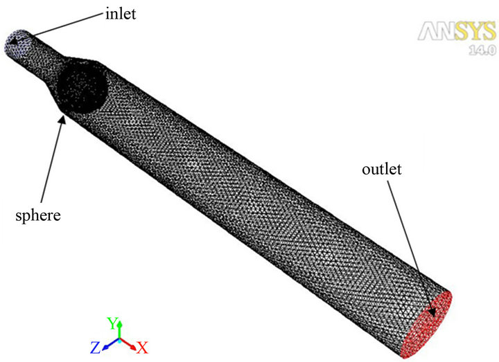
Figure 4. Perspective view of computational domain.
pling Scheme (Coupled), Bounded Central Differencing for spatial discretization of the momentum equation, and Switch Spatial Discretization Scheme for pressure (PRESTO!). The calculations were run for 10,000 time steps with 1E-3 seconds time step size, yielding 50 iterations per time step. At the outer surfaces inflow-outflow conditions are used and on the sphere and pipe surfaces nonslip boundary conditions are imposed. The validation of the numerical approach was performed through comparison of the drag coefficients against empirical results and published results for the flow past a sphere in the periodic vortex-shedding regime.
The periodical nature of the flow over the ball is considered to be due to periodical shedding of vortexes. To observe the vortexes shedding we present the iso-contours of plane velocity magnitude (Figure 5) and streamlines in the XY-plane (Figure 6) at four representing times per one shedding period.

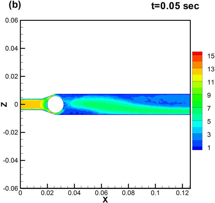
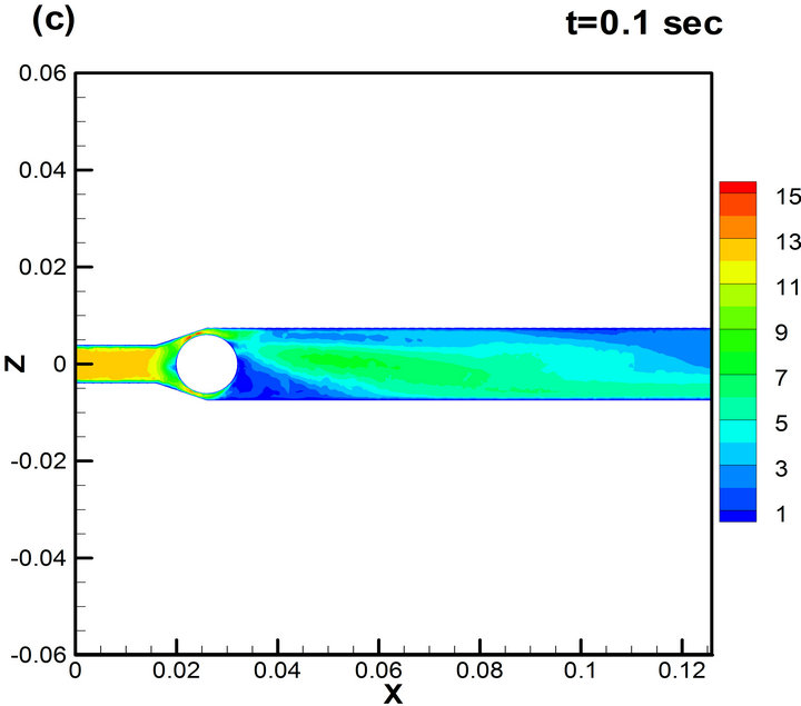

Figure 5. Mid-section (XZ-plane) velocity field (m/s) during one period of oscillation for d = 12 mm, Re = 3.4 × 10⁴.

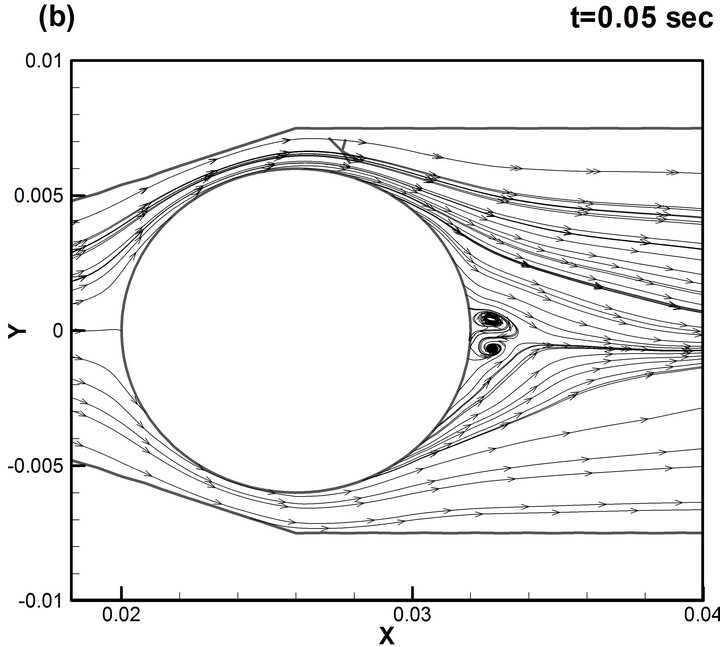
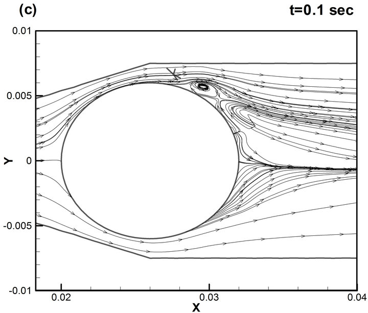
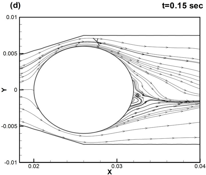
Figure 6. Streamlines of the flow in the XY-plane during one period of oscillation d = 12 mm, Re = 3.4 × 10⁴.
The development of vortexes is apparent in the velocity field, where a large number of smaller-scale eddies are merged into the stream wise wake. Figure 5 shows that the wake is rather narrow immediately behind the ball (due to the delayed onset of flow separation in the boundary layer). The wake width increases with distance from the separation point further downstream. Figures 5(a) and (b) shows that at the first stages the wake is sloped down relative to the axis of symmetry.
At later stages, shown on Figures 5(c) and (d), it is sloped up. Further time evolution of the wake is characterized by up and down shifting behind the ball. This regular motion of the wake about the stream wise axis is associated with inducing periodical force primarily in the span wise direction (or lifting force). The asymmetry is largest in the plane corresponding to the maximum instantaneous lift force.
More comprehension about the shedding mechanism, especially in the near-ball region, can be provided by examination of the distribution of the instantaneous streamlines over the ball. Figure 6 shows that the boundary layer before separation remains laminar and transition takes place at separation point developing into a number of vortexes. These vortexes are periodically separating and are expanding downstream of the sphere, an effect that leads, as was already pointed out, to a mean lift force. With increasing Reynolds numbers the separation point moves downstream and the vortex patches are more diffused. In addition, isocontours of the second invariant of the deformation tensor (or normalized Q-criterion) are presented to give a deeper insight into the vortical structures in the wake (Figure 7). According to [10], Q-method is one of the most appropriate methods of identifying a vortex in a turbulent flow, where Q is the positive second invariant of the deformation tensor. Figure 7 clearly shows that shear layer separating from the ball surface rolls up into a turbulent vortical structure to form a pair of strong stream wise vortices in the far wake. Zones of very low vorticity exist in the region immediately behind the ball. The large-scale vortexes are originating mainly from the separated shear layers where the vortexes are forming. The present simulation points to a mechanism of producing the lifting forces on the ball in which the large-scale coherent eddies are shed periodically into the wake. Prediction of the shedding frequencies yields good agreement with experimental measure-

Figure 7. Streamwise vortices in the wake (vortex identification by Q-criterion).
ments (Figure 2). Wake frequencies were obtained by calculation of the power spectrum of the span wise lift coefficient. Figure 8(b) shows that there is a clear dominant power peak that is associated with the major vortex-shedding frequency. The main peaks also appear for other Reynolds numbers similar to the experimental results.
In Figure 8(a) the history of lift coefficient, Cl, obtained from numerical simulations, is presented and a “non-chaotic” nature of the flow resulting from vortex shedding around the ball is illustrated. That is qualitatively evidenced that the process is not random. Another proof of this is shown in Figure 9, which represents measurements of the lift coefficient (curve 1, numerical simulation, same as in Figure 8(a)) and changes in amplitude vibration of ball in the valve (curve 2, experiment) as function of the time. These measurements confirmed the regularity of the ball vibration, and the qualitative similarity of the frequency oscillations in both the experiment and the calculations.
6. Conclusions
The following results were obtained in this study:
The stability and instability of the vibration of the ball in a valve were studied by an experimental method;
We received a criterion for rotational stability of the ball and described the main relationships that govern the rotation process;
The model in ANSYS Fluent was used to predict the flow over a ball in the valve for a range of Reynolds numbers up to 104;
Comparison of the present results with experimental data and empirical correlations showed that the predic-

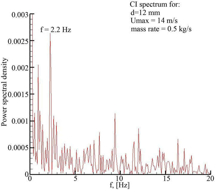
Figure 8. Time series (left) and Power spectrum (right) of CL for mass rate flow of 0.5 kg/sec.
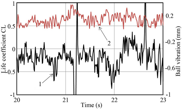
Figure 9. Oscillations lift coefficient (curve 1) and ball vibration (curve 2) versus time.
tions obtained by CFD software successfully reproduced most of the flow features associated with the vortex shedding;
This study demonstrates that it’s possible to control vibration in a hydraulic system.
REFERENCES
- F. C. Moon, “Chaotic Vibrations,” John Wiley & Sons, New York, 1987.
- A. L. Fradkov and A. Y. Pogromsky, “An Introduction to Control of Oscillations and Chaos,” World Scientific Series on Nonlinear Science, Vol. 25, 1998.
- R. D. Blevins, “Flow-Induced Vibration,” Kreiger, Malibar, Fla., 1994.
- C. M. Harris, “Shock and Vibration Handbook,” McGraw-Hill, New Yrok, 1995.
- G. Constantinescu, M. Chapelet and K. Squires, “Turbulence Modeling Applied to Flow over a Sphere,” AIAA Journal, Vol. 41, No. 9, 2003, pp. 1733-1742. doi:10.2514/2.7291
- G. Constantinescu, “Numerical Investigations of Flow over a Sphere in the Subcritical and Supercritical Regimes,” Physics of Fluids, Vol. 16, No. 5, 2004, pp. 1449-1466. doi:10.1063/1.1688325
- L. Grinis and E. Korin, “Hydrodynamic Method for Cleaning Inner Surfaces of Pipes,” Chemical Engineering & Technology, Vol. 20, No. 4, 1997, pp. 277-281. doi:10.1002/ceat.270200408
- Y. G. Panovko and I. I. Gubanova, “Stability and Vibration of Elastic Systems,” Moscow, 1987.
- I. I. Blekhman, “Synchronization in Science and Technology,” ASME Press, New York, 1988.
- J. Jeong and F. Hussain, “On the Identification of a Vortex,” Journal of Fluid Mechanics, Vol. 285, No. 1, 1995, pp. 69-94. doi:10.1017/S0022112095000462