Engineering
Vol. 3 No. 9 (2011) , Article ID: 7331 , 11 pages DOI:10.4236/eng.2011.39112
The Design of Heat Exchangers
1Applied Thermal and Hydraulic Engineering Laboratory SEPI-ESIME-IPN Professional Unit, Lindavista, México D.F.
2División de Estudios de Posgrado e Investigación, Instituto Tecnológico de Pachuca, Pachuca de Soto Hidalgo, México
E-mail: mtv49@yahoo.com, arthuro _reyes@yahoo.com.mx
Received June 22, 2011; revised August 11, 2011; accepted August 25, 2011
Keywords: Heat Changers, Energy Loss, Economic Dimensioning, Counterflow, Crossflow and Parallelflow
ABSTRACT
A relation between heat transferred and energy loss, for turbulent flow. In different tube arrangements, is made. The conditions are determined which decide the dimensions and velocities for a heat exchanger. Also, a reference to the economic dimensioning of heat exchangers is presented. In this study, the conditions which a heat exchanger must satisfy represent the best balance between the amounts of material employed. The investigation is restricted to the case of turbulent flow.
1. Introduction
The heat exchanger is an equipment that allows heat transference between two fluids at different temperatures. Heat exchangers are extensively used in industry due to their wide variety of construction and applications in heat transference processes for producing conventional energy such as condensers, heaters, boilers or steam generators. They provide an adequate surface for heat transference to occur and their mechanical and thermal characteristics allow high pressure and high temperature processes.
Heat exchangers are important, their optimization rises the competitiveness and allows energy saving. The necessity of saving and recovering energy for different processes in industry makes essential the develop of new manufacturing technology for heat exchangers in order to cover a wide range of operation conditions. In recent years, new software for design heat exchangers has been focus in adapting the equipment to the required process and new solutions have been found that make the design time shorter.
2. Heat Transfer and Friction Work
Let us first seek a relation between the heat transfer and energy loss. The problem is to determine the energy E which has to be spent in order that a quantity of heat Q may be transferred to a surface F, the average temperature difference being Q [1,2].
Symbols used:
Q = quantity of heat flowing per second.
G = weight of gas or liquid flowing per second.
Q = heat transfer coefficient.
Cp = specific heat at constant pressure.
Δt = temperature variation of medium during flow.
w = velocity of flow.
ζ = coefficient in pressure drop formula
l = tube length.
d = tube diameter.
γ = specific weight.
μ = absolute viscosity.
λ = thermal conductivity.
System units: m, kg, sec.
The heat given up to the surface F is:
 (1)
(1)
And the gas loses a corresponding amount of heat
 (2)
(2)
whence
 (3)
(3)
It is convenient to derive the expression of the energy loss first for longitudinal flow through the tubes, and applies it to the case of cross flow over a tube bank. The expression for the pressure drop in a tube is
 (4)
(4)
Putting the free gas section equal to f, and remembering that  and further that
  we obtain from Equation (3)
 (5)
(5)
The ratio of the pressure drop in the heat transfer depends, therefore, of the velocity with which the heating surfaces are swept. If we group together those quantities which depend on the velocity, and introduce the Reynolds number  and the Nusselt number
  we obtain the following relation between heat transfer and pressure drop:
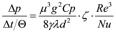 .
.
utting also:
 (6)
(6)
enables us to write the desired relation between the heat transfer and the energy loss in the case of longi tudinal flow through a tube, referred to 1 kg of medium flowing through the exchanger as
 (7)
(7)
Similar expressions may be obtained for the case of a tube bank with cross flow, if ζ is taken as denoting the pressure drop coefficient per tube row, if the bank is z1 the expression for the pressure drop becomes
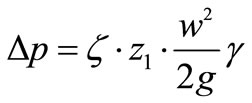 (4a)
(4a)
where w is the velocity at the narrowest point between the tubes. If  denotes the pitch of the tubes across the flow, and zq denotes the number of tubes per row also in the direction across the flow, then with
  we obtain
 (5a)
(5a)
and introducing Re and Nu gives
Let us put
 (6a)
(6a)
and we obtain a new form of Equation (7), for the case of cross flow:
 (7a)
(7a)
giving the relation between the energy loss and the heat transfer for cross flow.
It is seen that the first term of the Equations (7) and (7a) contains characteristic quantities of the medium and the tube diameter. This means that for a given tube diameter the heat exchanger is fully characterized by the number Z. Now the pressure drop coefficient ζ is function of Re, while Nu is a function of Re and of the Prandtl number, if we neglect the transition zone at the inlet, which is entirely permissible with cross flow exchangers many rows deep, or with longitudinal flow exchangers with relatively long tubes. But since the Prandtl number is purely a function of characteristic quantities of the medium, and we are interested only in a comparison of heat exchangers working with the same medium, and operating within the same temperature limits, Nu depends only on Re. This makes it possible to plot Nu as a function of Z. The Nu-Z diagram, therefore, gives a clear picture of the merit of a heat exchanger surface. Tube banks of different pitch are represented by different curves in the Nu-Z diagram. The higher a curve lies, the greater may be the heat transfer loading for a given energy expenditure, or, conversely, for a given surface and heat loading, the smaller the energy expenditure. Figure 1 which is drawn for gases contains curves relating to some of the most frequently used tube arrangements. In the case of cross flow, they are based on the values derived by Grimison from the tests of Pierson and Huge.
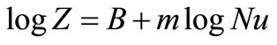
In order to make a comparison, curves for longitudinal flow have been inserted calculated with the aid of the formula given by Jung. It is seen that only at very high rates of heat transfer such as those which are achieved by the gas velocities attained in the Velox boiler, the longitudinal arrangement become more advantageous than the cross flow one. The curves giving the values of Z which are plotted in Figure 1, in a logarithmic scale is almost straight. It is, therefore, permissible when considering segments of these curves, and without introducing any appreciable error to assume the following relation
 .
.
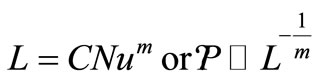
or,
 (8)
(8)
where B and m are constants whose value depends on the position in the diagram of the segment under consideration.
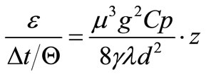
The expression for power loss can be written using Equation (7) and transforming Equation (3):
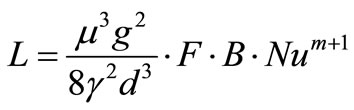 (9)
(9)
1. Crossflow, staggered tubes, pitch 1.25 × 1.25.
2. Crossflow, tubes in line, pitch 1.25 × 1.25.
3. Crossflow, tubes in line, pitch 1.5 × 1.5.
4. Crossflow, tubes in line, pitch 2 × 2
5. Crosssflow, tubes in line, pitch 3 × 3.
6. Longitudinal flow in a tube.
7. Longitudinal flow between tubes, pitch 1.5 × 1 .5.
8. Longitudinal tinybetween tubes, pitch 2 × 2.
9. Single tube in crossflow.
The pitch is expressed as times the tubes diameter.
The diagram shows for some common tube arrangements, the relation between the heat transfer number No and characteristic number Z for the energy loss. For any given arrangement of the tubes, there is a definite value of Z for every value of Nu of heat transfer, with the help of which the pressure drop and the exchanger surface may be obtained from the Equation (7) or (7a) [3].
3. The Condition for the Right Exchanger
The merit of an exchanger can only be judged when it is known what quantity of heat is equivalent to the mechanical energy which has to be supplied in the form of compressor or pump work to overcome the resistance of the exchanger. If the exchanger is an air preheater forming part of a steam power unit or a gas turbine then the overall efficiency of the plant or the efficiency when the exchanger is in service, determines the amount of the
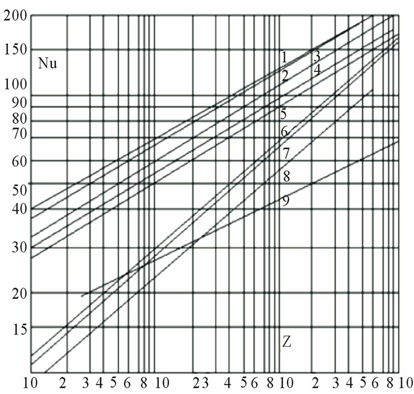
Figure 1. Relation between the energy loss and the heat transfer.
energy (expressed in kcal), to the heat consumption required to produce this energy [4,5].
On the other hand, if it is a case of plain heat transfer for instance, in blast heaters, furnaces, etc., where the energy absorbed in overcoming the resistance of the exchanger has to be supplied in the form of power purchased from an outside supply, then the cost of this power must be balanced against the cost of production of the more or less completely transferred heat in the exchanger. If h denotes the efficiency of the plant with which the heat energy of the fuel is converted into mechanical energy, then the economic performance of the exchanger is given by
 .
.
useful heat is, therefore, equal to the difference of the heat transferred and the heat required for the production of the mechanical work absorbed.
The right heat exchanger is, therefore, the exchanger which with a given surface and with a given diameter of tubes results in a maximum amount of useful heat. The condition for this is
 (10)
(10)
We shall now seek expressions for dQ and dL in terms of Nu.
Let the suffix 1 denote the hot medium, and the suffix 2 the cold one. The meaning of the symbols is made clear by the Figure 2. We may write for the temperature variation of the hot medium
 .
.
and similarly, that of the colder one is
 .
.
Further, let the mean temperature difference be given by
 .
.
The factor a depends only on e1 and e2, and is plotted in Figure 3 for counter flow, for cross flow and parallel flow, for the case e1 = e2. If we denote by k the overall heat transfer coefficient, the heat transferred is given by
 (11)
(11)
For a small change in the rate of heat transfer we have.
 .
.
Since kF may be treated as a single quantity.
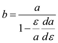
We put
 (12)
(12)
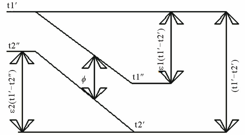
Figure 2. Diagram of temperature variation in an exchanger.
where b depends only on e1 and e2. From Equations (11) and (12), and from the relation 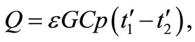 it is found that
 (13)
(13)
Curves for b are given in Figure 3. In the case of heat transfer in metal exchangers the thermal resistance of the exchanger wall may be neglected without introducing any appreciable error. Hence, it is permissible to write
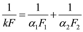 (14)
(14)
Differentiating and introducing the Nusselt number in place of the quantities  and
and  gives
gives
 (15)
(15)
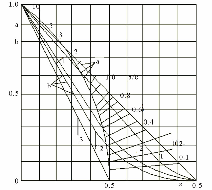
Figure 3. Characteristic numbers a and b of Equations (11) and (12) for e1 = e2 in the case of counterflow, crossflow and parallelflow.
The total power loss is the sum of the losses for the hot and cold mediums. We use Equation (9) and put
 (16)
(16)
and obtain for the total energy loss
 .
.
The change in loss with change of velocity is then given by
 (17)
(17)
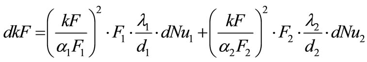
The change in heat quantity transferred with change of specific loading kF is given by Equation (12). Inserting Equations (12) and (17) in Equation (10) and taking into account Equation (15) gives
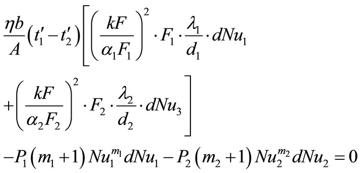 (18)
(18)
The coefficients of dNu1 and dNu2 must be equal 0. This gives two new equations namely,
 (19a)
(19a)
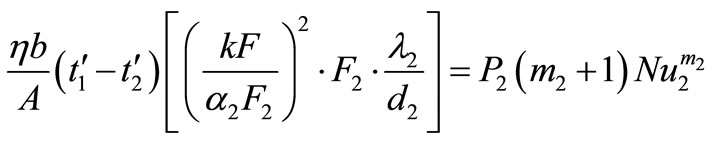 (19b)
(19b)
Dividing Equation 19 (b) by Equation 19(a), inserting for P1 and P2 the values given by Equation (16) and substituting Nu for a1 and a2 gives
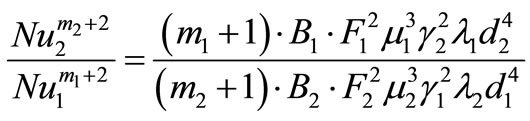 (20)
(20)
This equation determines the ratio of the velocities in the right heat exchanger; it does not, however, say anything about the absolute value of the velocities. It means that heat exchangers in which this ratio of the velocities is observed have for a given surface and a given heat quantity the lowest friction loss.
If we take the roots of Equations 19(a) and 19(b), and remembering that 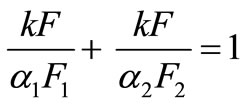 we obtain as the second condition for the right heat exchanger:
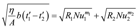 (21)
(21)
The factor R contains only constants.
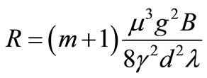 .
.
Two Equations (20) and (21) completely determine the most favourable heat exchanger. The resulting transcenddental equation must be solved by trial. The surfaces are found with the aid of the numbers Nu, and Nu, and since Nu is a function of the Reynolds number, the velocities w1 and w2 are also determinate. The dimensions of the heat exchanger are, therefore, fixed.
4. The Economic Dimensioning of a Heat Exchanger
It was seen in the first part that there is a function Z which serves as a criterion of the merit of tube arrangements in heat exchangers. In the second part the conditions fix the dimensions of the surface and sections of the right heat exchanger. The exchanger should, however, like every other apparatus be correctly dimensioned from the economic point of view, that is the total sum of the capital charges and of the running costs should be a minimum.
If P denotes the capital cost, n the interest and deprecition rate, then the capital chargers are
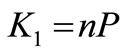 .
.
and if L is the power absorbed, h the efficiency, h the operating hours in one year and p the price per kilowatt-hour, then the power costs are
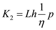 .
.
and the total costs in one operational year
 .
.
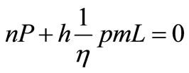
there should be a minimum hence,
 (22)
(22)
The capital costs will increase approximately in proportion to the exchanger surface, and for a given tube diameter, inversely proportionally to the heat transfer number, or
 .
.
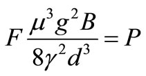
But according to Equation (9), the energy proportional to F ; hence substituting for
 .
.
differentiating and dividing by P
 (23)
(23)
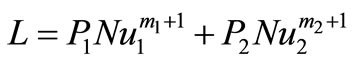
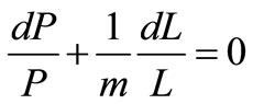
Dividing Equation (22) by Equation (23)
 (24)
(24)
The total costs in an operational year are a minimum when the capital charges amount to m-times the power costs. Within the range of practical application, that is, for Nu = 40 to 120 the curve which is over this range can be seen upon as a straight line, for instance curve 3 (cross flow heat exchanger with a tube pitch 1.5 × 1.5) gives an exponent m = 3.84 and a constant B = 166; for curve 7 (longitudinal flow with a tube pitch 1.5 d) the figures are m = 2.67 and B = 99 500.
The starting point for this study has been the as sumption of a fixed tube diameter and tube pitch. These and the choice between staggered or straight arrangement of the tubes are determined by dirt deposit and cleaning considerations. How closely these assumptions and the results of the calculation of the right heat exchanger may be adhered to in practice depends on manufacturing conditions, but in any case the above exposition serves as a guide to show in what direction and to what extent modifications are desirable.
5. Example
Designing a compact heat exchanger for heating wings continuous 20,000 kg/h of air from an inlet temperature (Tiair) 10˚C to an out temperature (air To air) of 55˚C heating fluid used water volumetric flow  (10 m3/h at temperature T of 95˚C, the input date are shown in Table 1 [6,7].
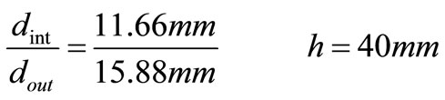
The density and heat capacity of both fluids are obtained from tables to standard atmosphere conditions. The characteristic of tube and of the wins are shown in Table 2.
Diagram inlets from primary and secondary of the compact heat exchanger are show in Figure 4.
Unit thermal water consumption
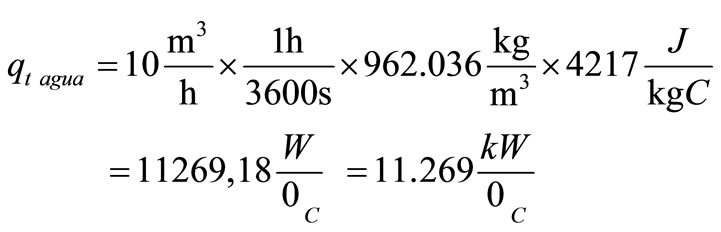
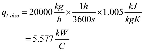
Unit thermal air consumption
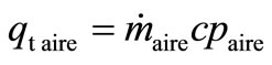
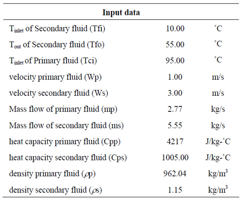
Table 1. Input data of the compact heat exchanger.
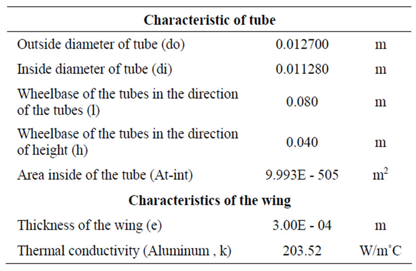
Table 2. Characteristic of tube and of the wing.
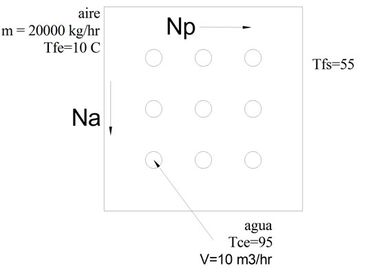
Figure 4. Diagram inlets from primary and secondary fluids.
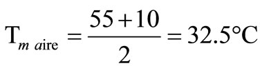
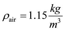
The density of air to Tm is show in Table 3.
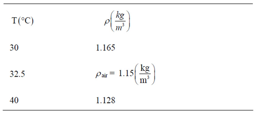
Table 3. Density of air to Tm.
Themal flow

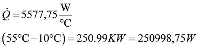
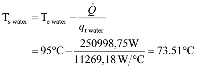
Temperature of exit of the water
Velocities are: 2.5 m/s and 3.5 m/s
Logarithmic mean temperature
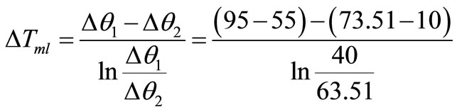
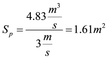
Surface airflow
Table gives the density of dry air at a temperature of 58.38˚C
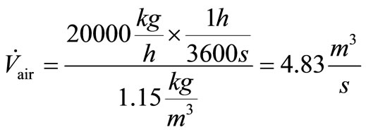
Volumetric air flow
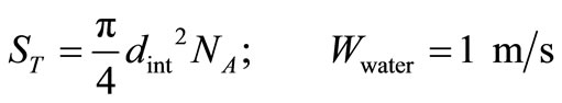
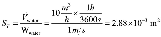
Surface water flow
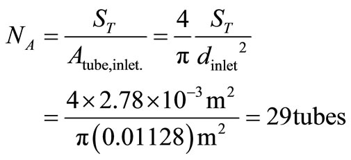
Number of tubes in the direction of height (H) heat exchanger
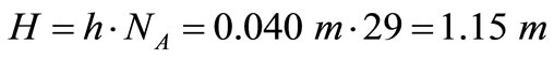
Height of heat exchanger
Winged tube length

In Table 4 are shown calculated values of Na, H and L to the compact heat exchanger.
Wing thickness, this value is assumed by the types of materials available in the industry
Calculation of Reynolds number (Re), Nusselt (Nu) and the convective coefficient (hi) of primary fluid
Whereas, dh = di; and the Prandtl Number (Prp), dynamic viscosity (mp) and conductivity of the primary fluid are determined from tables to the average temperature of primary fluid (Tmp). These values are shown in Table 5.
The values of Reynolds number, Nusselt number and convection coefficient inside of primary fluid are shown in Table 6.
Calculation of the mass velocity and maximum mass velocity of the secondary fluid.
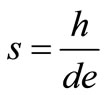
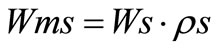
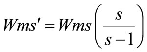
The values of mass velocity, maximum mass velocity and relationship s are shown in Table 7.
Calculation of hydraulic diameter (dh¢), Reynolds (Re) and convection coefficient (I) as a function the secondary fluid pitch between wing (p) Tables obtained forthe Prandtl number (Pr), the dynamic viscosity (ms) and thermal conductivity (ks) of secondary fluid at film temperature (Tmp). These values are shown in Table 8.
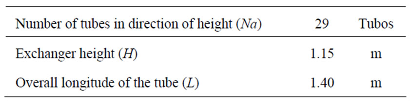
Table 4. Values of Na, H and L to the compact heat exchanger.
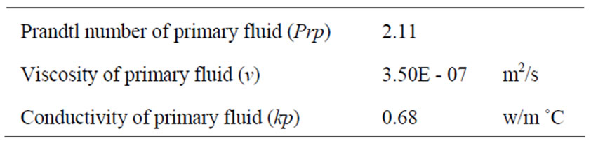
Table 5. Values of Prp, ν and kp.
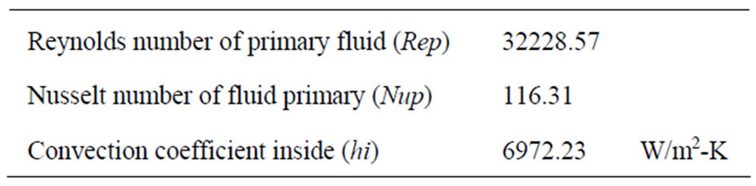
Table 6. Values of Rep, Nup and hi to the compact heat exchanger.
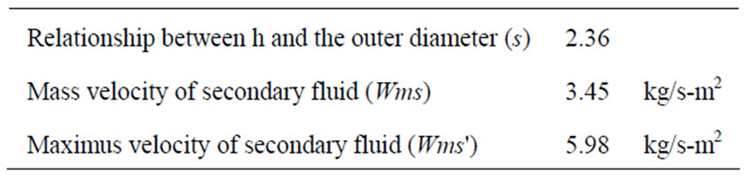
Table 7. Values of s, Wms and Wms of the secondary fluid.
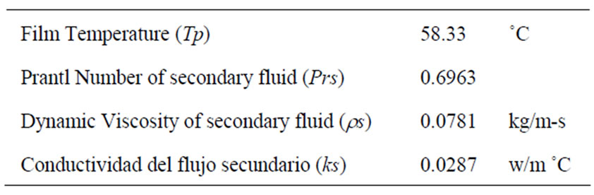
Table 8. Values of Tp, Pr, rs and ks of secondary fluid.
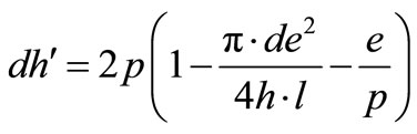
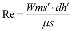
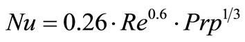
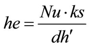
Table 9. show the values of m, dh', Re, Nu and he of the secondary fluid.
Calculation of equivalent diameter (dea) and efficiencies of wings. (Table 10)
In Table 11 show characteristics of wing, Aluminum considering.
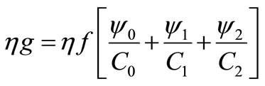
 , Relationship for the efficiencies.
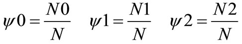
Calculation of the ratio number of wings with borders with the total number of wings.
Considering that N = Na x Np where Na is the number of tubes in direction of height and Np is the number of tubes in the direction of secondary flow.
Number of wings without borders
*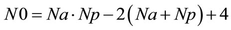
Number of wings with a border
*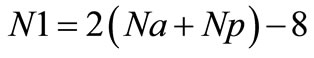
Number of wings with two borders
*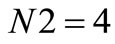
*Note: This means that the equations are modified as a function on Np. (Table 12)
Calculation of correction coefficients for the wings. (Table 13)

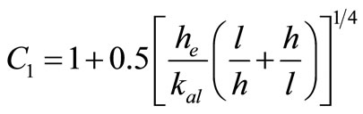
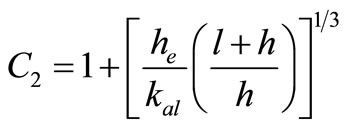
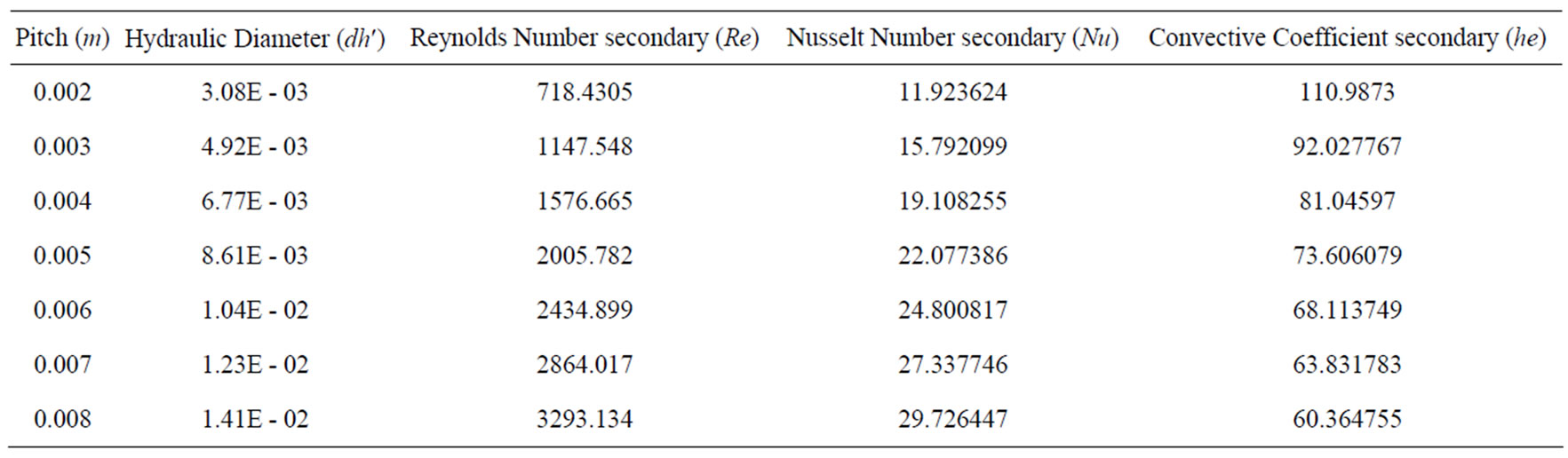
Table 9. Values of m, dh¢, Re, Nu and he of the secondary fluid.
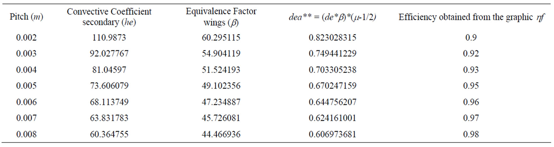
Table 10. Values of equivalent diameter and efficiencies of wings.
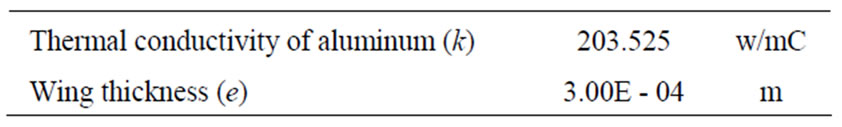
Table 11. Characteristics of Aluminum.
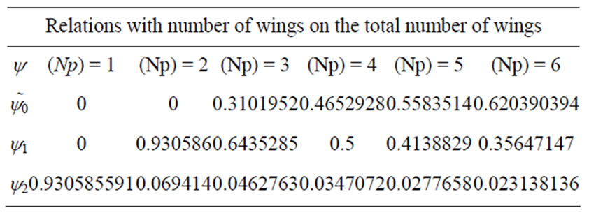
Table 12. Relations with number of wings on the total number of wings.
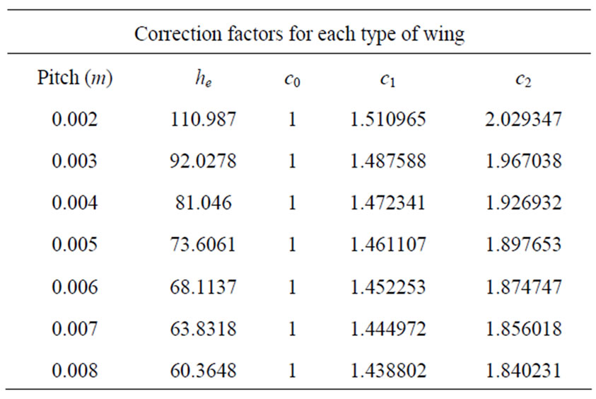
Table 13. Correction factors for each type of wing.
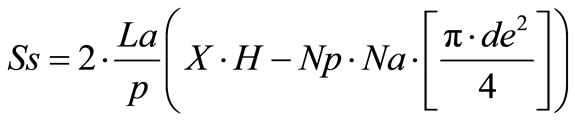
Calculation of the overall efficiency of the equivalent circular wing. (Table 14)
Calculation the overall surface heat Exchange where, . (Table 15)
Calculating the overall coefficient of heat transfer function and pitch Np
where,
*kt = conductivity of tube, et = Thickness of the wall of tube.
**The value  is neglected as being small compared to
 . (Table 16)
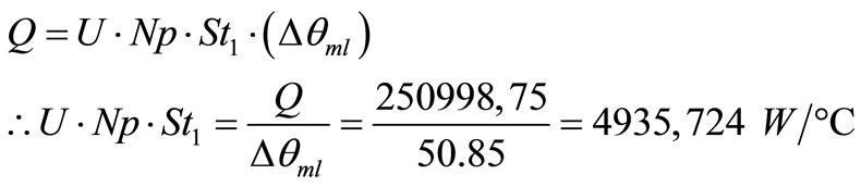
Calculation Heat flow based on Np and pitch (p)
 .
.
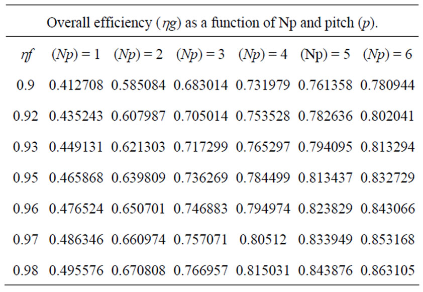
Table 14. Overall efficiency (hg) as a function of Np and pitch (p).
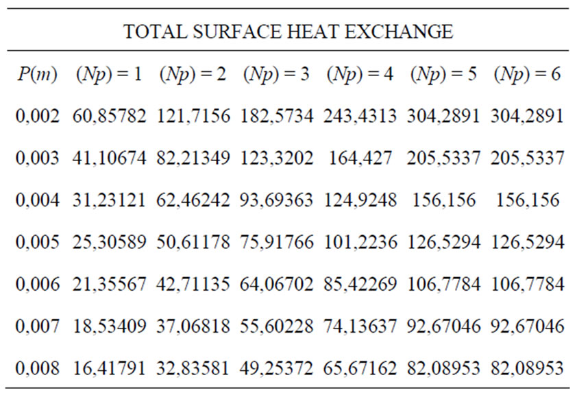
Table 15. Total surface heat exchange.
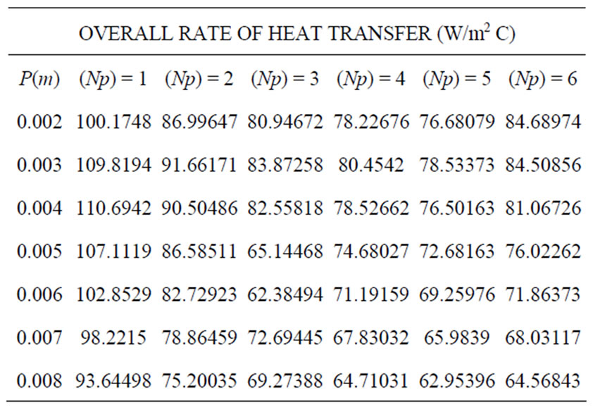
Table 16. Overall rate of heat transfer (W/m2 C).
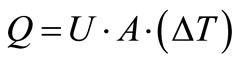
where A = Se = Overall surface heat exchange DT = Tml = Difference logarithmic mean temperature. (Table 17)
Calculation  for comparison of the relationship (
 ) as a function of Np and the pitch between wings.
Where:
St = Overall surface heat exchange with respect to pitch
Np = Pitch number of tubes in the direction of seconddary flow. (Table 18)
Selection based on the results obtained in the above table  can be compared to select the exchange with their respective sizes, data are compared

This variation is important for any factor that our team
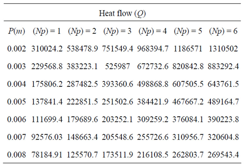
Table 17. Values of heat flow (Q).
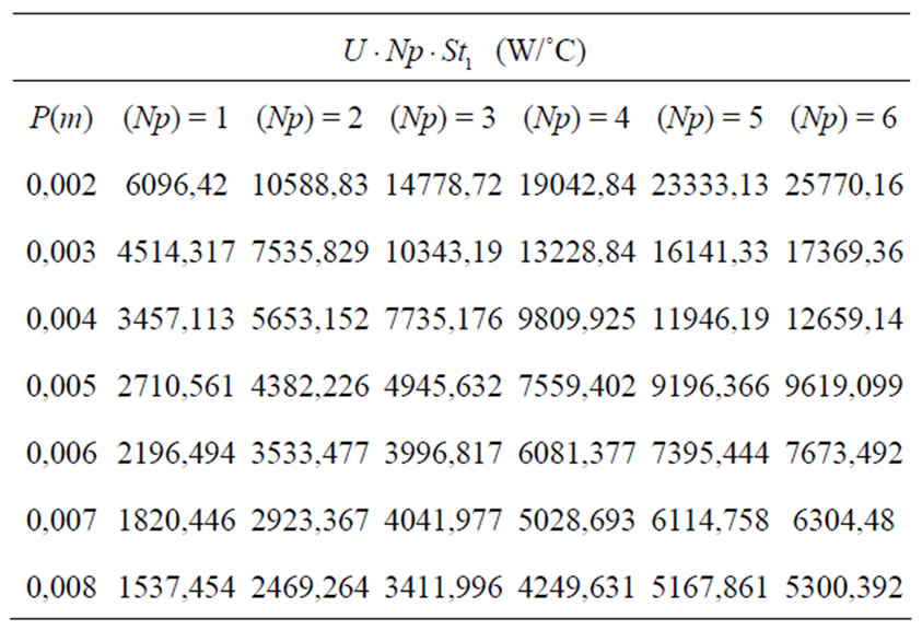
Table 18. Values of  (W/˚C).
needs to transfer more heat.
The selection of compact heat exchanger required to have 6 columns of tubes (Np = 6) in the direction of flow and pitch inlet wings of 8 mm, so X will be worth
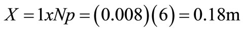
The dimensions of the compact heat exchanger will (L) x(H) x(X), (1.40 × 1.15 × 0.18) m.
With piping HWG 22 de = 12.7 mm y di = 11.28 mm.
The thick aluminum wings e = 0.3 mm and K = 203.52 W/m C. In Table 19 are shown characteristics of the exchanger.
6. Conclusions
This paper identifies the advantages of having the appropriate exchanger with working conditions, environmental conditions and economic aspects, it is also necessary to mention the following regarding the general utility of this work.
• In addition to the thermal design, mechanical design of heat exchangers is also a part of it. The mechanical design is done under the ASME Section VIII, which is entitled “Pressure Vessel Design”
• Although the subject of this work is the design of heat exchangers, which, as noted was achieved successfully, the utility of it is wider and there are several methods for the design of heat exchangers.
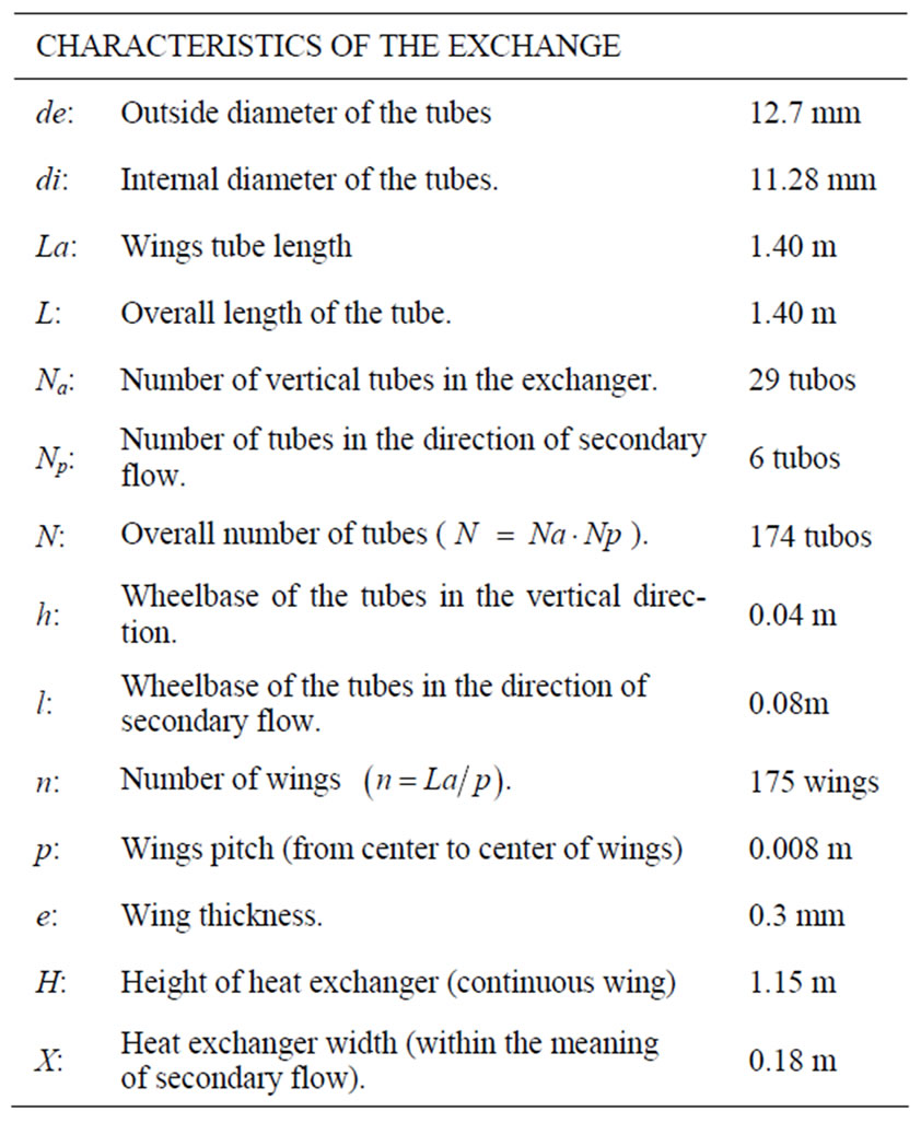
Table 19. Characteristics of the exchange.
• While this paper addresses just one example of a heat exchanger, this could vary, the same results in the thermal design, these variations are affected primarily for economic reasons or space.
7. REFERENCES
- D. Q. Kern, “Procesos de Transferencia de Calor,” 31th Reimpresión, CECSA, México, 1999.
- F. P. Incropera and D. P. Dewitt, “Fundamentals of Heat and Mass Transfer,” 5 th Edition, Wiley, New York, 2002.
- M. Serna and A. Jimenez, “A Compact Formulation of Bell-Delaware Method for Heat Exchanger Desing and Optimation,” Chemical Engineering Research and Desing, Vol. 83, (A5), 2005, pp. 539-550.
- R. K. Shah, P. Dusan and D. P. Sekulic, “Fundamentals of Heat Exchanger Design,” John Wiley & Sons, 2003.
- Z. H. Ayub, “A New Chart Method for Evaluating Single-Phase Shell Side Heat Transfer Coefficient in a Single Segmental Shell and Tube Heat Exchanger,” Applied Thermal Engineering, Vol. 25, 2005, pp. 2412-2420.
- Y. A. Kara and Ö. Güraras, “A Computer Program for shelland-tube Heat Exchanger,” Applied Thermal Engineering, Vol. 24, 2004, pp 1797-1805.
- R. Castillo, “Diseño Computacional de Intercambiadores de Calor de Coraza y Tubos por el Método Delaware,” Tesis de Maestría, Instituto Politécnico Nacional, México, 1999.