Engineering
Vol. 3 No. 6 (2011) , Article ID: 5341 , 7 pages DOI:10.4236/eng.2011.36072
Slope Stability Analysis of Itakpe Iron Ore Mine, Itakpe, Nigeria
1Department of Mineral Resources Engineering, The Federal Polytechnic, Ado-Ekiti, Nigeria
2Department of Mining Engineering, Federal University of Technology Akure, Akure, Nigeria
3Department of Civil Engineering, Federal University of Technology Akure, Akure, Nigeria
E-mail: rasheed4u1@yahoo.com
Received February 24, 2011; revised April 1, 2011; accepted April 10, 2011
Keywords: Slope stability, Itakpe iron ore mine, Intersection, Critical zone, Failure
ABSTRACT
The slope stability of the Itakpe Iron Ore Mine has been carried out using computer software, ROCKPACK III. One hundred and twenty three dip and dip direction values were obtained using compass clinometer. The Itakpe Iron Ore Mine was divided into four benches; 241 - 258 m, 263 - 275 m, 276 - 286 m and 308 - 312 m. Joints along the discontinuities were mapped. The data obtained were analyzed using ROCKPACK III. The results indicate that the discontinuities within the critical zone are potentially unstable and can lead to planar failure. The Markland test carried out for wedge failure indicates that the intersection of the discontinuities does not fall within the critical zone hence there cannot be any wedge failure of the slope within the level 241 - 258 m. The presence of discontinuities that plot within the toppling critical zone indicates that there is potential toppling failure on the slope at the 276 - 286 m level. In addition, the toppling failure test shows the absence of discontinuities that plot within the toppling critical zone and this indicates the absence of potential toppling failure of the slope at the 308 - 312 m level. The result of the study will be useful to the management of the Itakpe iron ore mine in having a proper understanding of the failure mechanism of the slopes.
1. Introduction
The Itakpe iron ore deposit lies 4 kilometre south – west of Ajabanoko iron ore deposit and is located within latitude 8˚ and 9˚ and longitude 7˚ and 8˚. The Itakpe iron ore deposit is operated as an open pit mine and has multiple benches. The bench geometry was chosen based on the stability assessment of the slope. The stability of a slope should be viewed from both the safety aspect and economic aspect. The stability of bench walls in an open pit mine is a major safety issue, and there is usually a slow movement of the rock formation before a failure actually occurs [1].
In the process of mining the ore an opening is created which necessitates the creation of slope. The actual slope angle used in the mine depends upon 1) the presence of haulage roads, or ramps, necessary for the transportation of the blasted ore from the pit, 2) possible blast damage, 3) ore grades, and 4) economical constraints [2]. Rock slope failures are geological events controlled by natural processes [3]. Slope failures are typically considered at three levels: 1) Global in which the entire pit wall might collapse the mine 2) inter-ramp in which a partial wall failure might substantially affect the recovery of ore 3) bench in which slope failure only affects the local operations in the vicinity of the failed bench [4].
The optimum slope design of a pit requires the determination of the most economic pit limit which normally results in steep slope angle as in this way the excavation of waste is minimised [4]. In any economic open pit mine, a variety of slope instabilities may be present at various locations in the mine at anytime, the successful management of these features is the art of good open pit mining [3]. In general as the slope becomes steeper, the stripping ratio (waste to ore ratio) is reduced and the mining economics improves [4]. Therefore the primary objective of a mine slope designer is to reduce the quantity of waste to be excavated and maximise the quantity of ore produced. This is very important especially at the planning stage of the mine. The difficulty in determining the acceptable slope angle stems from the existence of uncertainties associated with the stability of the slopes [4].
The fundamental issues to be addressed in predicting slope failures can be grouped into the following three categories [5]:
1) knowledge of the strength, geological structure and deformability of the potentially unstable rock mass including;
• the orientation, spacing and continuity of the joints that intersect the rock mass;
• the location and orientation of the larger faults or weak zones that may subdivide the jointed rock mass into separate zones or domains and
• the quality of the rock mass in each domain in detail.
2) Knowledge and understanding of failure mechanism.
3) Knowledge of how to analyse these failure mechanisms for stability.
Surface deformations and slope stability are very important issues to the open pit mining industry [6]. Slope instability can be a potential source of danger for people and equipment, also disrupting mine scheduling and increasing the cost of mining production [7-9].
1.1. Geology of Itakpe Iron Ore
The Itakpe ridge consists of mainly Precambrian rocks, which are represented by:
2) Meta – sedimentary rock series
1) The migmatite – gneiss complex are variably migmatised, undifferentiated gneiss with intercalation of amphibolites, each of which is 2,800 - 2,000 million years.
2) Metasedimentary series comprises various schist, gneiss, meta conglomerates. The ferruginous quartzite is enclosed in the series and forms the iron ore occurrence in the ridge. The metamorphism is more of green schist than the amphibolites facieses series, each 200 - 680 million years old.
3) The older granites consist of granitoid rocks of plutonic and metasomatic origin whose formation is in association with the Pan African orogeny. They include diorites, quartz, coarse grain porphiritic granite, granite gneiss, pegmatites each of 680 - 480 million years. The ore strike east west generally and it dips south, ranging from 58˚ to 86˚. On the Itakpe deposit, three main ore bodies have been delineated, each comprising a group of ferruginous quartzite bands or lenses. The three ore bodies are explained as follows [10]:
a) The Northern ore body occurs at the Northern flank of the ridge. It has a strike length of 400 m and a length of 200m along dip direction. The thickness is approximately 60 m at the surface and thins at depth to about 30 m. Dips of the ore lenses are generally to the South at angles that range from 40˚ to 60˚. Extensive intrusive activity, which involves the emplacement of a charnokite body, has disrupted a large portion of the ore body.
b) The central ore body extends along strike up to 200m. It increases in thickness from West to East. Two small ore lenses 35 and 15 m thick, which extend southwards, coalesce at a depth of 150 m to the main ore body.
c) The Southern ore body dips steeply at 70˚ - 80˚ and extends for more than 500 m at a thickness of approximately 15m.
The deposit comprises twenty-five (25) ore layers. According to dip, strike, attitude and location, fourteen (14) layers of iron ore have been grouped, they can be found within four (4) groups; Northern, Central, Intermediate and Southern.
From a tectonic point of view, the Itakpe deposit is confined to the southern limb of a large Itakpe-Ajabanoko anticline with enclosing rocks and conformable ore layers striking sub-latitudinally and slightly bending to the north and dipping southward at angles ranging from 40˚ to 80˚ with local minor-fold complications [11]. The average iron ore content of the ore deposit was determined to be approximately 35% [12].
The main classification adopted for the Itakpe iron ore deposit is based on [13]:
1) Magnetite ore Black streak
2) Heamatite ore Reddish brown
3) Magnetite—Heamatite ore 50% magnetite
4) Heamatite—Magnetite ore 50% magnetite
1) Rich ores (45% Fe in about 5% of mine)
2) Medium ores (31% - 45% Fe in about 82% of mine)
3) Lean ores or poor grade ores (20% - 30% in about 13% of mine)
1) Coarse grain
2) Medium grain
3) Fine grain
1.2. Theoretical Framework
1) Plane failure is a common type of translational failure and occur by sliding along a single plane which daylights in the slope face (i.e., the dip of the failure plane is less than that of the slope). When considered in isolation, a single block may be stable. Forces imposed by unstable adjacent blocks may give rise to active and passive block failures. Some designers regard plane failure as a special case of wedge failure and as a result it is not common in rock slope. For plane failure to take place, the following geometrical condition must be met [14]:
a) The plane on which sliding occurs must strike parallel (±20˚) to the slope face.
b) The failure plane must “daylight” in the slope face.
c) The dip of the failure plane must be greater than the angle of friction of this plane.
d) There must be a release surface, which provides a negligible resistance to the sliding
2) Wedge failures. A combination of two planar discontinuities the slope face and the upper slope surface form wedge failures. The condition for movement to occur is that the line of intersection of the wedge daylights in the slope.
3) Rotational factures in rock slope are usually found only in structureless overburden material, highly weathered rock or very high slopes in closely jointed material. Either circular or non-circular failure surfaces may be generated.
4) Circular failure: Circular failures may occur in rock masses which are so intensely fractured in relation to the scale of the slope that they may be considered as randomly jointed and isotropic. In highly weathered materials, non circular failures may occur along a combination of existing joints and failure through weak but previously intact material. In circular failures, there is no structural pattern and the failure surface is free to find the line of least resistance through the slope and the failure geometry is circular [14].
This is the most common type of low slope failure in soil or in material such as mine waste in which no regular pattern of geologic features exist [15].
5) Toppling failure: Toppling facture involves rotation of columns or blocks of rock about some fixed base. In toppling failure the direction of dip of plane is usually towards the rock massive. Toppling failure occur as a result of sliding and or toppling of individual slopes of rock [14]. For toppling failures to take place, the discontinuity causing failure must be inclined parallel or almost parallel to the cutface [14]. This means that the dip direction must be 180˚ to that of the cutface.
1.3. Bench Parameters for Itakpe Iron Ore Deposit
The maximum sustained grade for the access roads at the Itakpe iron ore mine is 8% thereby making the stopping distance to be equal to 62 m when the truck is descending and a brake is applied. The haulage road width is designed in such a way as to allow for easy movement of the haulage equipment. The width criteria used is based on the widest equipment that was selected under equipment selection. The width of the equipment selected varies from 4 - 6 m; hence the width of two lanes varies from 10 - 20 m.
Safety berms in the design of haulage ways are used as a safety feature. The berm design used in the study is the trapezoidal berm which is formed from unconsolidated waste rocks that was excavated from the deposit during the process of mining the iron ore. The safety berms also prevent boulders and mining equipment from rolling over to the lower bench. The slope of the berm at present is irregular while the berm slope angle proposed for Itakpe iron ore mine is 30˚. Also large boulders will be used to support the waste rock along the width of the haulage road. The height of the berm varies from 1.3 - 2 m (Table 1).
2. Materials and Method
Geologic Data Collection
Geologic data such as dip and dip direction values were measured using compass clinometers The Itakpe iron ore mine was divided into the East and West pits. These pits were mapped along the benches. The mapping was carried out starting from a lower bench level of 260m and this was continued up to the bench level of 390m.The altitude of the bench level was determined using Geographic Positioning System (GPS) equipment. One hundred and twenty three dip and dip direction values were obtained from the Itakpe iron ore deposit .The equal area projection method was used to graphically represent the data as poles and great circles.
The west pit was divided into four levels of 241 - 251 m, 253 - 275 m, 276 - 286 m, 308 - 312 m. ROCKPACK III which make use of stereonet projection was used to plot the pole plot of the slope values. A stereonet is the projection of planes and a 3-dimensional reference sphere
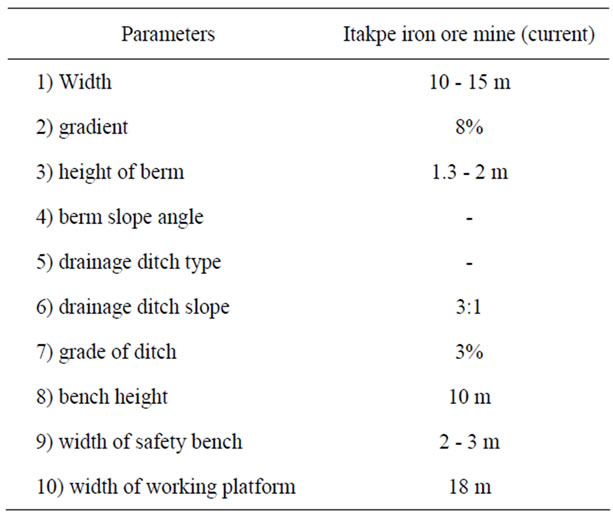
Table 1. Parameters of haulage road and catch bench.
though they might pass to a 2-dimensional representation.
Markland test was carried out for the four benches identified above.The two conditions that must be met for sliding to occur using Markland test are: 1) the discontinuity must have dip (θ) that is steeper than its friction angle (Φ), 2) the discontinuity must daylight from the slope face in a down-dip direction, i.e. the discontinuity must dip in the same general direction as the slope face, but less steeply. The two conditions identified above were represented on stereonet in the form of a crescent-shaped critical zone.Markland’s test is an extremely valuable tool for identifying those discontinuities that could lead to planar failures in the rock mass and for eliminating other discontinuities.
The condition for Wedge failure analysis in Markland test is that in order for Wedge failure to occur, the line made by the intersection of the planes creating the wedge must plunge more steeply than the friction angle and less steeply than the dip of the slope face and in a direction such that it daylights from the slope face. The conditions for Toppling failures in Markland test is that toppling will occur only if the layers strike parallel to the strike of the slope.
3. Results and Discussion
One hundred and twenty three dip and dip direction values were obtained from the Itakpe iron ore deposit. The friction angle obtained for the Itakpe iron ore deposit is 36˚ which is the minimum dip angle for which sliding will occur along a discontinuity while the cohesion value is 55 kN/m2 (Table 2). Some of the input data used includes bench height of 10 m, rock density of 3.80 kN/m2 and inclination of failure plane of 50˚ (Table 3). The data were plotted using ROCKPACK III. The slope of Itakpe iron ore deposit was divided into four bench levels; 241 - 258 m, 263 - 275 m, 276 - 286 m, and 308 - 312 m. The slope on level 241 - 258 m contains discontinuities that are mainly made of small joints. Forty dip and dip direction values were plotted for the 241 - 258 m level. Figure 1 indicates the dip vector plot of the values plotted. The discontinuity dip vectors plotted which fall within the critical zone dip more steeply than the friction angle of 36˚ while those that are outside the friction circle dip less steeply than the slope face. Figure 1 also shows the Markland’s test carried on the dip vectors. Markland test is a valuable tool for identifying those discontinuities that could lead to planar failures in the rockmass and this allow for the elimination of other discontinuities. The discontinuities within the critical zone are potentially unstable and can lead to planar failure. Markland test for wedge failure was also carried out. The great circle of
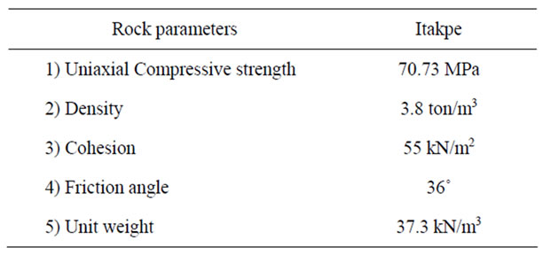
Table 2. Rock properties of Itakpe iron ore mine.
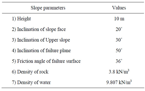
Table 3. Plane failure analysis input data (Itakpe iron ore mine).

Figure 1. 241 - 258 m Markland test (Itakpe iron ore mine).
dip and dip direction values 18/023 and 78/074 were plotted at the centre of the two clusters identified. The two great circles represent the discontinuities of each cluster. The intersection of the discontinuities does not fall within the critical zone hence there cannot be any wedge failure at the slope within the level 241 - 258 m bench level (Figure 1).The intersection point is the plunge and trend. The kinematic in Markland was carried out for Toppling test. There is no likelihood of toppling failure because the discontinuities do not fall within the toppling zone (Figure 2).
The dip and dip direction values for the 263 - 275 m bench level was obtained from the disconti-nuities such as small joints were plotted on the stereonet using ROCKPACK III. Figure 3 shows the dip vector plot of the discontinuities. Markland’s test was carried out for the slope on the 263 - 275 m level. Although there are some discontinuities in the critical zone, the intersection of the two great circles did not occur in the critical zone. The dip and dip direction of the two great circles are 025/20 and 067/25 and their point of intersection is outside the critical zone (Figure 3). Although some discontinuity values fall within the critical zone but the fact that the intersection of the great circle did not occur within the critical zone indicates that there cannot be planar failure on the slope at that level. The wedge failure-analysis in Markland carried out for the slope on 263 – 275 m level indicates the absence of potential wedge failure because the two great circles did not intersect in the critical zone (Figure 3). The toppling failure analyses carried out for the 263 - 275 m level indicates that the absence of any discontinuity in the toppling zone (Figure 4).
Figure 5 indicates the dip vector plot of discontinuities of slope on 276 - 286 m level. The Markland test carried out shows the presence of discontinuities that plot within the critical zone which indicates the possibility of
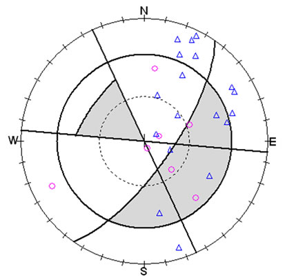
Figure 2. 241 - 258 m (Toppling test).

Figure 3. 263 - 275 m Markland test.
planar failure. However wedge failure analysis carried out using two great circles with orientations 076/76 and 112/43 also indicates the possibility of wedge failure, because of the intersection of the two great circles within the critical zone (Figure 5). Also the presence of discontinuities that plot within the toppling critical zone indicates that there is potential toppling failure on the slope at the 276 - 286 m level (Figure 6).
Figure 7 shows the dip vector plot of discontinuities
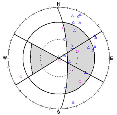
Figure 4. 263 - 275 m Toppling test.
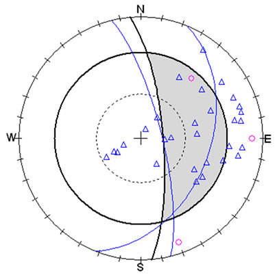
Figure 5. 276 - 286 m Markland test.
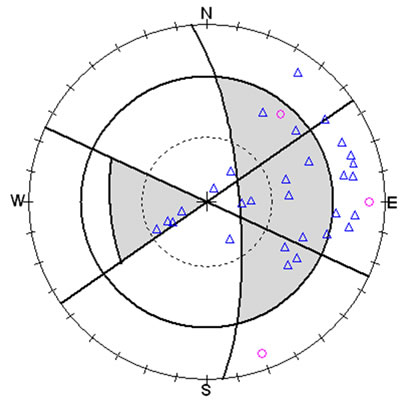
Figure 6. 276 - 286 m Toppling test.
of slope on 308 – 312 m level The Markland test carried out shows the presence of discontinuities that plot within the critical zone which indicates a potential planar failure (Figure 7). Also the wedge failure test carried out using two great circles with orientations 115/36 and 058/57 have the intersection of the point within the wedge critical zone which indicates there is possibility of potential wedge failure of slope at the 308 - 312 m level. In addition the toppling failure test shows the absence of discontinuities that plot within the toppling critical zone which indicates the absence of potential toppling failure of the slope at the 308 - 312 m level (Figure 8).
The one hundred and twenty three dip and dip direction values was plotted and the dip vector plot is indicated in Figure 9. Markland test was carried out using four great circles of 090/85, 073/39, 041, and 026/20 and the intersections of these great circle indicates possibility of planar failure (Figure 10). The toppling test carried out further confirmed that there is no possibility of toppling failure (Figure 10).However the result of the analysis carried out using Rockpack III indicates a factor of safety of 0.61 which is below 1 considered as mini-
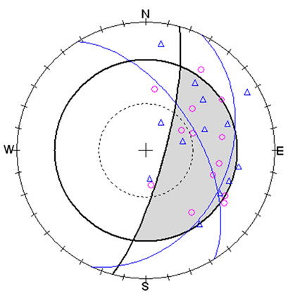
Figure 7. 308 - 312 m Markland test.
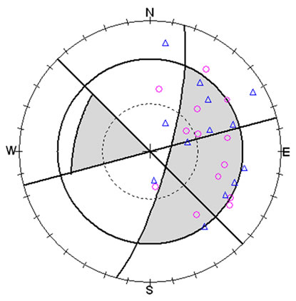
Figure 8. 308 - 312 m Toppling test.
mum value for a stable rock slope (Table 4).
4. Conclusions and Recommendations
Slope stability analysis has been carried out for the East pit of the Itakpe iron ore mine. The result obtained indicates the presence of conditions that could lead to planar failure on the bench level 241 - 258 m and bench level 263 - 275 m. However the absence of discontinuities that plots within the toppling critical zone indicates the absence of potential toppling failure. Furthermore the result of the analysis carried out indicates a factor of safety of 0.61 which is below 1 considered as minimum value for a stable slope. From the result of this work, the management of NIOMP is requested to provide good drainage network in other to avoid further development of gullies
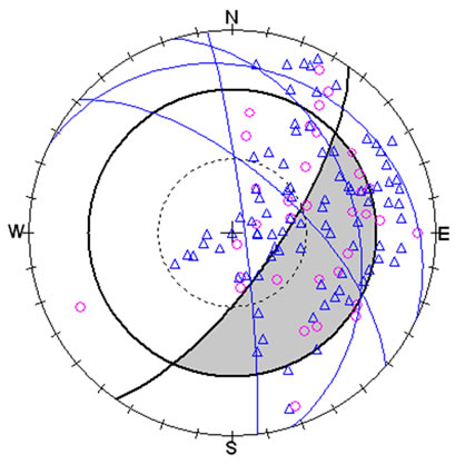
Figure 9. Total dip vector plot (Markland test).

Figure 10. Total dip vector (Toppling test).
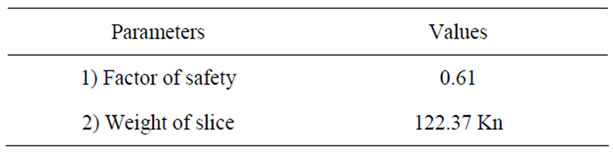
Table 4. Result of plane failure analysis.
along the slope face.
5. REFERENCES
- A. Chrzanowski and R. Wilkins, “Accuracy Evaluation of Geodetic Monitoring of Deformation, in Large Open Pit Mines,” 3rd IAG/12th Fig Symposium, Baden, 22-24 May 2006.
- J. Sjoberg, “Large Scale Slope Stability in Open Pit Mining: A Review,” Lulea University of Technology, Lulea, 1996.
- E. Hoek, J. Read, A. Karzulovic and Z. V. Chem, “Rock Slopes in Civil and Mining Engineering,” Proceedings of the International Conference on Geotechnical and Geological Engineering, Melbourne, 19-24 November 2000.
- O. K. H. Steffen, L. F. Contreras, P. J. Tebrugge and J. Venter, “A Risk Evaluation Approach for Pit Slope Design,” 42nd US Rock Mechanics Symposium, ARMA 08-231, San Francisco, 29 June - 2 July 2008.
- J. R. L. Read, “Risk and Accepted Practices in Open Pit Mining Geomechanics, Keynote Address,” Aus IMM, Australia, November 2003, pp. 3-5.
- A. Jarosz and D. Wanke, “Use of InSAR for Monitoring of Mining Deformations,” Proceedings of FRINGE 2003 Workshop, Frascati, 1-5 December 2003.
- P. Lilly, D. Xn and P. Walker, “Stability and Risk Assessment of Pit Walls at GHP Ore’s Mt Whaleback Mine,” An International Conference on Geotechnical and Geological Engineering, Melbourne, 2000.
- K. Kido, R. Yoshinaka, K. Hagiwara and K. Sasaki, “Stability Analysis and Deformation Behaviour of Large Excavated Rock Slopes,” An international Conference on Geotechnical & Geological Engineering, Melbourne, 2000.
- E. N. Bromhead, “The Stability of Slopes,” Blackie Academic & Professional, 2nd Edition, London, 1992, pp. 1-217.
- M. A. Olade, “Precambian iron ore deposit and its environment at Itakpe ridge, Okene, Nigeria,” Institution of Mining and Metallurgy, Transaction Section B, Vol. 87, 1978, pp.1-9.
- A. O. Solomon, O. A. Adewole, A. U. Garba, A. A, Odunaike, S. M. Kollere and P. O. Ajiboye, ”Study on Magnetic Concentration of Nigerian Itakpe Sinter Concentrate to a Midrex-Grade Concentrate,” Maejo International Journal of Science and Technology, vol. 3, no 3, 2009, pp. 400-407.
- P. U. Umunakwe, “Developing a New Mine: The Itakpe case,” Proceedings of the Annual Conference of Nigeria Mining and Geosciences Society, Jos., 1985.
- NIOMP, “Itakpe project Report. Parts I and II,” Unpublished Report, NIOMP, Itakpe, 1979.
- E. Hoek and J. W. Bray, “Rock Slope Engineering,” Institution of Mining and Metallurgy, London, 1981.
- E. Hoek, “Recent Rock Slope Stability Research at the Royal School of Mines, London,” In: C.O. Brawner and V. Milligin, Eds, Geotechnical Practice for Stability in Open Pit Mining, The American Institute of Mining, Metallurgical, and Petroleum Engineers, Inc., New York, 1982, p. 27.