Materials Sciences and Applications
Vol.4 No.9(2013), Article ID:36708,11 pages DOI:10.4236/msa.2013.49066
Rolling Circle Amplification on Biotin-Streptavidin Complexes Immobilized to Activated Cyclic Polyolefin Surfaces
![]()
1Molecular Biology Research Laboratory, Boston University, Boston, USA; 2Department of Biomedical Engineering, Boston University, Boston, USA; 3Department of Biology, Boston University, Boston, USA.
Email: hoh@bu.edu
Copyright © 2013 Herin Oh et al. This is an open access article distributed under the Creative Commons Attribution License, which permits unrestricted use, distribution, and reproduction in any medium, provided the original work is properly cited.
Received July 19th, 2013; revised August 17th, 2013; accepted August 29th, 2013
Keywords: Cyclic Polyolefin; Ligation Mediated Rolling Circle Amplification; SNP Detection
ABSTRACT
Cyclic polyolefin (COP) is an inexpensive hydrophobic material with low auto-fluorescence, high light transmittance and thermal stability, broad chemical resistance and no non-specific protein binding. Here, the hydrophobic alkane COP was modified to have carbonyl functionalities through oxygen plasma and chemical etching treatments to increase usefulness for chemical and biochemical applications. Then, biotin-hydrazide was used to create biotinylated surfaces that bound streptavidin. A biotinylated target oligonucleotide was subsequently bound to the immobilized biotin-streptavidin and ligation mediated rolling circle amplification-based (L-RCA) SNP detection was demonstrated.
1. Introduction
Cyclic polyolefins and cyclic polyolefin copolymers (COP) (Figure 1(a)) are newly developed exceptionally inert, temperature resistant, optically transparent, hydrophobic materials with low auto-fluorescence advantageous for many applications [1]. The inert hydrophobic surface and low reactivity allow for ready adsorption of small hydrophobic molecules, but hinder biochemical and chemical reactions requiring hydrophilic environments, and/or the covalent immobilization of biomolecules.
In-solution (“homogeneous”) biochemical assays and procedures done on COP surfaces (Table 1) include: plasma clotting time [2], isoelectric protein fractionation, assessment of surface hydrophilicity [3], PCR [4,5], mRNA extraction [6] and DNA extraction [7,8]. Biochemical “heterogeneous” assays using biomolecules immobilized to modified COP surfaces (Table 2) include sandwich immunoassays [9-11], in situ oligonucleotide synthesis [12], DNA hybridization [13], and PCR [5,14]. Chemical surface modification strategies used with COP are similar to those of glass, silicon and other polymers, i.e., wet chemistry, oxygen plasma and photografting treatments (for review see Wittman and Marquette, 2012 [15]). Silica film-covered COP surfaces were used for lateral flow assays [2], sandwich immunoassay [9,10], nucleic acid extractions [8], and synthesis of DNA mi-

Figure 1. Surface chemistry. (a) COP structure. R1 and R2 represent the organic side chains attached to the core monomer. (b) Reaction of biotin hydrazide with an aldehyde [taken from http://www.piercenet.com].

Table 1. Published procedures using modified COP surfaces for homogeneous (in solution) reactions.

Table 2. Published procedures using modified COP surfaces for heterogeneous reactions.
croarrays [12]. A commonly used COP surface treatment is UV-irradiation grafting of a benzophenone (BP)/acryl amide or methylacrylate [3,6,8,16,17]. Nexus Biosystems (San Diego CA) sells COP microtiter plates (Aurora Microplates) with hydrophilic surfaces created using mild plasma oxygen treatments that are said to be compatible for a variety of biochemical applications. Biotinylated polymer surfaces (for reviews see Smith et al., 2006 [18]) are widely in use in the diagnostic and biotechnology arena (polystyrene and polycarbonate plastics) because of their stability and flexibility. Here, biotinylated (Figure 1(b)) COP surfaces created through plasma oxygen and chemical treatments were used to bind streptavidin. Then, a biotinylated target oligonucleotide bound to streptavidin was utilized for ligation-mediated isothermal rolling circle amplification (L-RCA) detection of a single nucleotide polymorphism (SNP) (Figure 2(a)). This approach can be applied to bind a wide variety of molecules to polyolefin surfaces to perform enzymatic reactions.
2. Materials and Methods
2.1. Plaque Fabrication
A hot press (Heated Press 4386, Carver Inc., Wabash, IN, USA) with temperature and pressure control was used to create flat plaques from COP beads (Zeonex 690R, Zeon Chemicals LP, Louisville, KY) following previously established procedures [8]. In brief, a lower, thin, stainless steel metal sheet (McMaster-Carr #9759k13, Santa Fe Springs, CA), with a kapton film having COP resin beads arranged in a circular (~2 inches diameter) pattern was placed onto the hot press. Four metal shims (Feeler gauge set, Grainger, Chicago, IL, USA) were used as spacers on each corner of the steel plate to ensure uniform desired thickness. Then, another kapton film and a second (upper) steel plate were placed on top of the beads. The arranged stack was placed on the lower platen and the hot press was brought to 198˚C (~25˚C above the glass transition (Tg) temperature for Zeonex 690R) and 3000 psi pressure applied for 5 min to create plaques ~1 mm thick. Another thinner COP cover plaque was made using the same method except 1000 psi pressure was applied for 5 min.
2.2. Wells and Channel Fabrication
Hot embossing from an epoxy master was used to form the microfluidic channels and wells. The epoxy mold was fabricated from a 4-inch silicon wafer with SU8 photoresist (MicroChem, MA, USA) layer patterned using standard photolithography [19]. SU8 was applied to clean, pre-baked silicon wafers, spin-coated twice at 2000 rpm for 30 sec, UV-radiated using a mask aligner (Karl Suss MA-6; Suss America, Waterbury, VT), developed for 12 min in a Shipley AZ400K developer (AZ Electronic Materials, Branchburg, NJ) and baked at 150˚C for 15 min. The resulting patterned SU8 photoresist served as a mold to create a negative replica cast made of poly-dimethyl siloxane (PDMS, Silgard 184, Dow Chemical Corporation, Marlborough, MA). The PDMS base elastomer and curing agent were mixed in a 10:1 mass ratio, poured onto the patterned SU8 mold, degassed for 30 min and cured at 80˚C for more than 2 hours. The epoxy mold was fabricated by mixing resin:curing agent (3:2 (v:v)) (Conapoxy (FR-1080, Cytec Industries Inc., Olean, NY). The mixture was poured into the PDMS mold and cured at 120˚C for 6 hours.
The COP plaque cut to a rectangular shape (3.6 cm × 7.6 cm) was aligned on the epoxy mold, followed by a kapton film and a silicon pad in a vacuum chuck. After a vacuum was applied, the formation was placed in the hot press at 170˚C and 600 psi (= 1 ton) for 8 min. The epoxy mold created 0.5 mm deep, 2 cm long and 1 mm wide wells in preformed plaques (volume = 10 µl).
The channels were created by placing the fabricated welled substrate onto the cover plaque between thin metal plates in the press at the temperature of 170˚C, adjusted the metal sheets near to each other but not touching (i.e. at a pressure of about 0 psi) for 2 min. The pressure was adjusted to 250 psi for 2.5 min. NanoPorts (N-333, Upchurch Scientific, Oak Harbor, WA) were fit onto the chip after drilling a 0.16 cm hole at the edges of the wells. The chips were aligned with the drilled holes and sealed with epoxy glue (J-B KWIK, Sulphur Springs, TX). A 3 cc syringe connected to an automatic syringe pump (Razel Syringe Pump Model A and KD Scientific Syringe Pump) was used to pump solution through the channel. In specific, a female luer (see N-333, Upchurch Scientific, Oak Harbor, WA) twisted onto the syringes connected to a short nut (NanoTight F-333NX, Upchurch Scientific, Oak Harbor, WA) attached to 0.16 cm tubing was inserted into the ferrule. The other tubing end was inserted into another NanoTight with a ferrule twisted into the NanoPort.
2.3. COP Surface Modification
Carbon side chains of COP surface were oxidized using oxygen-plasma and acid treatments. Before processing, the COP plaques (with plain surfaces, wells or microchannels) were ultra-sonicated in acetone, methanol and ddH2O, respectively, for 15 min each and submerged in 70% (v:v) ethanol for ~1 hour. The cleaned chips were stored in dust-free ziplock bags at room temperature.
Dried clean chips were treated face up in an SPI Asher (O2) Plasma Cleaner (SPI Plasma Prep II, SPI Supplies,

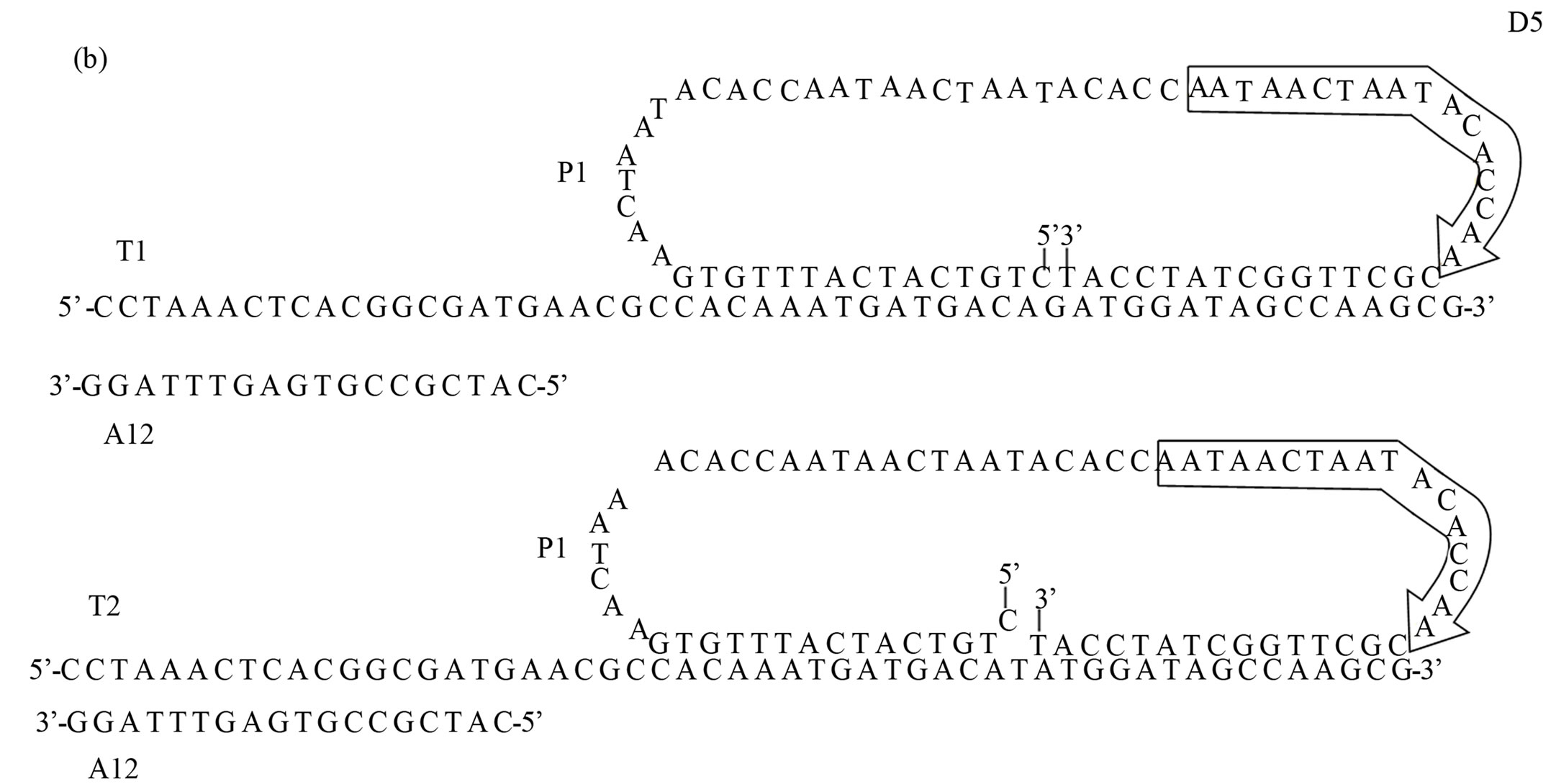
Figure 2. Schematic of SNP detection on modified COP surface using L-RCA. (a) Biotinylated target (T1 or T2) oligonucleotides (light green) were bound to streptavidin (grey) immobilized to a biotinylated COP surface. Biotin is indicated in light blue. Shown are the support oligonucleotide A12 (dark green), the open circular probe P1 (dark blue), and the Cy5 labeled detection oligonucleotides D5 (red) (b) Oligonucleotide sequences. Adapted from Sabanayagam et al. [19].
West Chester, PA) with an oxygen flow of 4 Standard Cubic Centimeters per Min (sccm), maximum current (varied between 95 - 100 mA), 10 psi, for 10 - 120 sec (timed from when the vacuum reached 0.15 Torr). Oxidation by acid treatment was performed by incubation of the chips for 15 - 120 min at 70˚C in freshly prepared 0.26 M chromic acid [K2Cr2O7/H2O/H2SO4 (4.4/7.1/88.5 (% wt)], or 18 M sulfuric acid. After treatment, the chips were rinsed with distilled water until the wash reached neutral pH. Increased hydrophilicity was crudely assessed by examining surface spread of 5 µL of distilled water.
2.4. Biotinylation of Activated Surfaces
Immediately after activation, a 1.2:6 (mM:mM) Biotin LC hydrazide (#21339 Pierce, Rockford, IL): 1-Ethyl- 3-[3-dimethylaminopropyl] carbodiimide hydrochloride (#77149, Pierce, Rockford, IL) in 2-(N-morpholino) ethanesulfonic acid (MES) buffer (#28390 Pierce, Rockford, IL) was injected into the wells or channels that were covered with a glass coverslip and placed in a covered petri dish to prevent evaporation, and incubated overnight at room temperature with gentle shaking. In some experiments, MES buffer was injected in the place of biotin-LC-hydrazide as a negative control. The samples were washed by injecting the wells/channels with 5 volumes of 1X PBS (137 mM NaCl/2.7 mM KCl/4.3 mM Na2HPO4/1.5 mM KH2PO4, (pH 7.4)) for 15 sec, followed by rinsing the chip in 50 ml 1X PBS, pH 7.4 for 15 sec.
2.5. Streptavidin Binding
The biotinylated surfaces were incubated for 30 min with gentle shaking at room temperature with a 0.1 mg/ml bovine serum albumin (New England BioLabs) to block non-specific protein binding, followed by washing as described above. Then, 1.6 or 2 µM fluorescein conjugated streptavidin (# 21224, Pierce, Rockford, IL) in 0.06 mM sodium phosphate and 0.94 mM NaCl solution was injected and the chips were incubated for 30 min at 37˚C with gentle shaking away from light. Unbound streptavidin was removed by washing as described above.
2.6. SNP Detection by L-RCA
All biochemical reagents were purchased from New England Biolabs, (Ipswich, MA). The experimental conditions used had earlier been optimized by us [20]. All oligonucleotides were purchased from Eurofin MWG Operon (Huntsville, AL). The target oligonucleotides (T1 and T2) 53 bases in length were biotinylated at their 5’-ends. The support oligonucleotide A12 was Cy5 labeled at its 5’-end in initial experiments to assess streptavidin-biotin immobilization. The 15 bases at the 5’-and 3’-ends of the 73 base open circular probe, P1, is complementary to the target oligonucleotides T1 and T2, completely or with a 1 base 5’-terminal mismatch, respectively. The detection oligonucleotide, 15 bases in length and complementary to the extension product of the T1, had a 5’-end Cy5-label. A biotinylated target/ support oligonucleotide complex was bound to immobilized streptavidin. The stiff double-stranded portion of the complex raised the 3’-end single stranded region of the partially duplexed DNA 6.12 nm above the channel surface. The complex was formed by incubating 5 µM T1 or T2, 5 µM A12 and 10 µM P1 oligonucleotides together, heating to 95˚C, then slowly cooling (0.1˚C/sec) to 20˚C in a DNA Engine Peltier Thermal Cycler (BioRad Laboratories, Hercules, CA). Ten µl of the pre-annealed oligonucleotide complex was injected to the wells and the samples were incubated at room temperature for 30 min with gentle shaking. Unbound complex was removed by washing as described above. Ligation reactions in the wells were carried out by incubating the immobilized P1 - T1 (or T2) - A1 complex at 37˚C for 30 min in 1X T4 DNA ligase buffer supplemented with 0.1 M NaCl and 0.32 U/µl DNA ligase in a total volume of 50 µl. The wells were washed by injection with 5 volumes (50 µl) of 0.1 M sodium phosphate/1 M NaCl, pH 6.6 (SPE) buffer, and the chips rinsed in 80 ml SPE buffer for 15 sec in order to remove any unbound components.
The RCA reactions were performed in the wells after injection of Phi29 polymerase buffer (1X), 1 mM dNTPS, 0.1 mg/ml BSA, and 0.85 U/µl Phi29 polymerase in a total volume of 50 µl incubated at 31˚C for 1 hour with gentle shaking. Control reactions were processed in the same manner but in the absence of both enzymes (T4 DNA ligase and Phi29 polymerase). The wells were injected with 5 volumes of SPE buffer and then rinsed in SPE buffer for 15 sec in order to remove any unbound material. Five µM of a Cy5-labeled detection oligonucleotide, D5, complementary to the L-RCA product (Figures 2(a) and (b)) was injected into the wells and the chips were incubated in a DNA Engine Peltier Thermal Cycler at 95˚C for 30 sec, 52.6˚C for 3 hours. The wells were rinsed by injection of 5 volumes of SPE buffer and the chips rinsed in 80 ml SPE buffer for 15 sec to remove unbound detection oligonucleotide before imaging.
2.7. Imaging Acquisition and Analysis
Measurements were performed using a prism-based total internal reflection upright Olympus BX51 microscope (Olympus, Center Valley, PA) with the UPlanFl 10x/0.30 Phase objective, and the Olympus Optical BH2-RFLT3 Mercury Burner. The MetaMorph software package (Molecular Devices, Sunnyvale, CA) was used for image acquisition. In each experiment, images for each fluorophore were acquired with the same exposure time, and processed in the same manner. The raw images captured using a 12-bit camera (CoolSNAp fx camera (Photometrics, Tucson, AZ) were converted to 16-bit tif format for processing. Signals from the 12-bit range (0-4095) clustered near the zero end of the 16-bit black and white scale (0-65535). Processing and analysis of fluorescence was initially performed using with an in-house protocol developed in MATLAB (The Mathworks Inc., Natick, MA) (see Appendix) that removed out of focus regions. Later experiments used ImageJ software obtained from http://rsbweb.nih.gov/ij/(National Institute of Health, Bethesda, Maryland) and analyzed images taken from the center of the well/channel to eliminate out of focus regions.
A rectangular area was cropped from the center of the well or channel in order to avoid edge and out-of-focus regions and processed in ImageJ (ImageJ functions are indicated in italics below). Reference processing values were obtained for each fluorophore by optimizing the signal from the highest intensity image (Slice) in a stack using the Auto Adjust Brightness & Contrast function, and applying these values to all the stacked images. The Adjust Threshold function was used to calculate the Otsu threshold value for the entire stack, and converted the grey scale images to binary images. The percent area covered and total pixel intensity were calculated for each slice in the image stack using the Analyze Particles function, i.e., generating a 16 bit image showing the particles painted with a value corresponding to the particle number. The total intensity of each slice was calculated after optimizing the signal from the highest intensity image (see above) using the View Histogram. Total intensity was obtained by summation of the product of binned intensity values x pixels (count) within the Otsu threshold region.
3. Results
The goal of this study was to create modified COP (Figure 1(a)) surfaces suitable for immobilization of biomolecules and for biochemical reactions. Briefly, flat substrates (plaques) were fabricated from COP beads. The plaques were then imprinted with an epoxy mold to create wells. Surface activation was done using plasma oxygen and chemical etching treatments to create carbonyl groups on the COC surface. The activated surfaces were reacted with biotin hydrazide to create a functional biotinylated layer that bound streptavidin. Biotinylated primer oligonucleotides bound to immobilized streptavidin were used to perform L-RCA (Figure 2) using a system similar to that described by us [20].
3.1. Surface Modification
The amount of fluorescently labeled streptavidin that bound to biotinylated surface was used to evaluate surface modifications. The greatest surface coverage occurred when the chips were treated for 30 sec in the oxygen plasma chamber (4 sscm; 10 psi; 0.78 Torr) followed by a 1 hour chromic acid treatment resulting in maximum biotin mediated streptavidin immobilization level with at least 50% surface coverage (Figure 3). Reproducibility of the optimized conditions is shown in Figure 4. About 30% coverage was detected in an experiment where a sulfuric acid treatment for 60 min was followed by a 30 sec of oxygen plasma treatment (data not shown). Although preliminary, these results suggest that less caustic sulfuric acid can be substituted for chromic acid.
3.2. Functionality of Immobilized Streptavidin
The ability of immobilized streptavidin to bind biotinylated target oligonucleotide was assessed (Figure 5

Figure 3. Calculated well surface coverage as a function of time of oxygen plasma treatment. Plasma oxygen treatments 30 sec (red), 50 sec (blue) and 120 sec (black). Images were processed and analyzed using MATLAB.

Figure 4. Immobilization of fluorescein labeled streptavidin to biotinylated COP surfaces. Example of images from two different chips (S1 and S2) demonstrating reproducibility of the optimized methods with 30 sec oxygen plasma treatment and 1 hour chromic acid etching. R1 and R2 indicate different regions within the same sample. Images were processed and analyzed using MATLAB.
and Table 3). In this experiment, a complex of pre-annealed Cy5-labeled support oligonucleotide (A12) and biotinylated target oligonucleotides (T1) was incubated with the streptavidin coated surfaces. A reaction without biotin hydrazide treatment was used as negative control. The fluorescent Cy5 signal was significantly higher in wells treated with biotin hydrazide indicating that biotinylated target oligonucleotide was successfully and specifically bound to biotin-immobilized streptavidin.
3.3. L-RCA and SNP Detection
In situ SNP detection involved several coupled steps: (pre) hybridization formation of the complex, an SNP detection ligation step followed by polymerase extension and then a final hydridization step for detection of the RCA product (Figure 2(b)). The pre-annealed oligonucleotide complex composed of a biotinylated target (T1 or T2), a support oligonucleotide (A12), and probe oli-

Figure 5. Immobilization of target and Cy5-labeled support oligonucleotide complex to streptavidin immobilized to a biotinylated COP surface. (a) Different sites (R1 and R2) within the same wells treated (upper) and not treated (bottom) with biotin-hydrazide. (b) Images in (a) after Otsu thresholding and conversion to binary values showing count mask using ImageJ. See Table 3 for mean percent coverage and total intensity values.
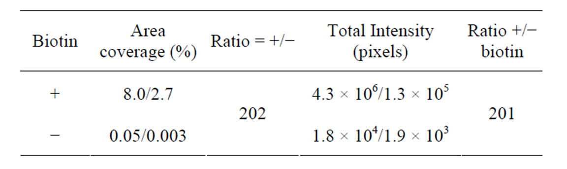
Table 3. Analysis after immobilization of a complex of preannealed Cy5-labeled support oligonucleotide (A12) and biotinylated target oligonucleotides (T1) with and without prior immobilization of biotin. Mean area coverage and total intensity of fluorescein fluorescent. Mea, (i.e., streptavidin coated surface) are shown. Two regions from the same sample were analyzed. Also see Figure 5.
gonucleotides (P1) was immobilized to the streptavidin layer. Template oligonucleotides T1 and T2 differ by a single nucleotide. The P1/T1 complex contains a totally matched duplex region, whereas the P1/T2 complex contains a single C:T mismatch at the 5’-terminus of P1.
DNA ligase, sensitive to single-base end mismatches, was used to create a closed circular template with the matched (P1/T1) but not with the mismatched complex (P1/T2). Then, a Phi29 polymerase extension reaction primed by the 3’-ends of the immobilized capture target oligonucleotides (T1 or T2) was carried out. RCA reactions occurred on circularized templates only. In the absence of circularization (P1/T2 complex), the extension reaction can only proceed to the end of the open circular probe template. The RCA product was detected by subsequent hybridization to a Cy5-labeled detection oligonucleotide complementary to extension product.
Significant Cy5 fluorescence was detected in the wells after the ligation and RCA reaction of the P1/T1 complex (Figures 6 and 7). Little or no fluorescence was detected when ligase and polymerase were omitted (Figure 6). The percent area covered with fluorescence was 10-fold higher in wells where enzymes were present (Table 4)
The discrimination ratio between matched and mismatched alleles was taken as the total intensity ratio between matched (T1:P1) vs mismatched (T1:P2) complex 105 (Figure 7 and Table 5). In a previous study by us [20], using the same L-RCA system on streptavidin coated silicon microwells, a hundredto thousand-fold discrimination ratio was reported. In those experiments [α-32P] dTTP incorporation was used for detection. We estimate the signal from the previous experiments should be ~18-fold greater than the signal reported here because single nucleotide incorporation was measured. Assuming the background is constant in both experiments, the amount of product detected in both experiments appears to be within a similar range. Sensitivity could be increased in these experiments using fluorescently labeled nucleoside triphosphates rather than detection oligonucleotides.

Table 4. Analysis of a matched L-RCA reaction with (+) and without (−) enzymes using the D5 detection oligonucleotide. Mean area coverage and total intensity of fluorescein fluorescent signal (i.e., streptavidin coated surface) are shown. Also see Figure 6.
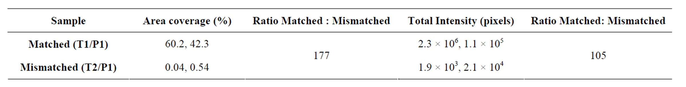
Table 5. Analysis of L-RCA of matched and mismatched templates assessed by hybridization of a Cy5 labeled detection oligonucleotide. Mean area coverage and total intensity of Cy5 fluorescent signal (i.e., L-RCA product) are shown. Two regions from the same sample were analyzed. Also see Figure 7.
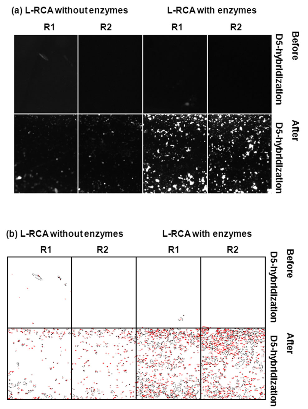
Figure 6. Hybridization of Cy5-labeled detection primer D5 to L-RCA products. Two regions, R1 and R2, from the same sample were analyzed. (a) Shown are results after L-RCA and before and after D5 hybridization. L-RCA reactions had both ligase and polymerase, or were missing both enzymes. See Table 4 for percent coverage values and total intensities. (a) Pre-processed images. (b) Images in (a) after Otsu thresholding and conversion to binary values showing count mask using ImageJ. See Table 4 for percent coverage and total intensity values.
4. Conclusions
COP is a second-generation polymer with improved characteristics over older polymers for biological applications, albeit the innate inert hydrophobic surface and low

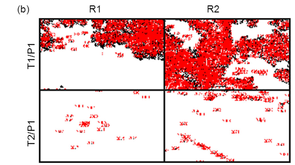
Figure 7. Comparison of L-RCA using matched (P1:T1) and mismatched (P1:T2) complexes on COP surface. Two regions, R1 and R2, from the same sample were analyzed. (a) Pre-processed images. (b) Images in (a) after Otsu thresholding and conversion to binary values showing count mask using ImageJ. See Table 5 for percent coverage and total intensity values.
reactivity hinder many applications. Here, the functionality of several created modified COP surfaces (charged hydrophilic, biotinylated, and streptavidin-coated) was demonstrated. These surfaces can be used to immobilize different biomolecules in multiple ways; both covalent and through biotin-streptavidin linkage (for reviews see Wittmann and Marquette, 2012 [15] and Smith et al., 2006 [18], respectively).
Further, we demonstrate that the modified wells/channels can be used for bioassays; thereby increasing the potential use of COP devices as diagnostic platforms. Prior to this work, the only reported COP based enzymatic assay using an immobilized substrate is a primer extension reaction [14], although there are several reports on the use of COP channels for in-solution, homogeneous enzymatic assays (see Table 1). The experimental L-RCA used in these experiments is not ideal and ongoing experiments are testing other formats. For instance, 3’- and 5’-end mismatches do not greatly affect duplex stability and are difficult to distinguish (for review, see Cantor and Smith, 1999 [21]). Hence, mismatches placed at 1 to 2 nucleotides from an end might lead to improved discrimination. Ongoing experiments are testing the use of biotinylated support oligonucleotide that can capture complementary end tagged sequences added to target fragments to improve versatility, reducing the steps involved by combing the enzymatic and detection steps, and converting all the manipulations to a more efficient flow through format.
The need for low-cost portable devices to perform analytical tasks is steadily growing and moving biological and biomedical microchip design towards flowthrough systems that allow multi-step reactions to be performed easily [22,23]. Microfluidic devices have minimal volume, reagent and power requirements, and they are portable and inexpensive, which allow for versatile designs, integration with other devices, and immense parallelization [24-26]. Economic incentives dramatically favor the development of cost-effective fabrication of such devices [27], driving microchip for bioassay manufacturing to polymers rather than silicon and glass.
REFERENCES
- W. D. Niles and P. J. Coassin, “Cyclic Olefin Polymers: Innovative Materials for High-Density Multiwell Plates,” Assay and Drug Development Technologies, Vol. 6, No. 4, 2008, pp. 577-590. doi:10.1089/adt.2008.134
- M. M. Dudek, R. P. Gandhiraman, C. Volcke, A. A. Cafolla, S. Daniels and A. J. Killard, “Plasma Surface Modification of Cyclo-Olefin Polymers and Its Application to Lateral Flow Bioassays,” Langmuir, Vol. 25, No. 18, 2009, pp. 11155-11161. doi:10.1021/la901455g
- T. B. Stachowiak, D. A. Mair, T. G. Holden, L. J. Lee, F. Svec and J. M. Frechet, “Hydrophilic Surface Modification of Cyclic Olefin Copolymer Microfluidic Chips Using Sequential Photografting,” Journal of Separation Science, Vol. 30, No. 7, 2007, pp. 1088-1093. doi:10.1002/jssc.200600515
- Q. Cao, M. C. Kim and C. Klapperich, “Plastic Microfluidic Chip for Continuous-Flow Polymerase Chain Reaction: Simulations and Experiments,” Biotechnology Journal, Vol. 6, No. 2, 2011, pp. 177-184. doi:10.1002/biot.201000100
- Y. Fuchiwaki, H. Nagai, M. Saito and E. Tamiya, “Ultra-Rapid Flow-Through Polymerase Chain Reaction Microfluidics Using Vapor Pressure,” Biosensors and Bioelectronics, Vol. 27, No. 1, 2011, pp. 88-94. doi:10.1016/j.bios.2011.06.022
- A. Bhattacharyya and C. M. Klapperich, “Differential Gene Expression Using mRNA Isolated on Plastic Microfluidic Chips,” Conference Proceedings of IEEE Engineering in Medicine and Biology Society, Vol. 2009, 2009, pp. 1067-1070.
- M. Mahalanabis, J. Do, H. Almuayad, J. Y. Zhang and C. M. Klapperich, “An Integrated Disposable Device for DNA Extraction and Helicase Dependent Amplification,” Biosensors and Bioelectronics, Vol. 12, 2010, pp. 335- 359. doi:10.1007/s10544-009-9391-8
- A. Bhattacharyya and C. M. Klapperich, “Thermoplastic Microfluidic Device for On-Chip Purification of Nucleic Acids for Disposable Diagnostics,” Analytical Chemistry, Vol. 78, No. 3, 2006, pp. 788-792. doi:10.1021/ac051449j
- J. Raj, G. Herzog, M. Manning, C. Volcke, B. D. MacCraith, S. Ballantyne, M. Thompson and D. W. Arrigan, “Surface Immobilisation of Antibody on Cyclic Olefin Copolymer for Sandwich Immunoassay,” Biosensors and Bioelectronics, Vol. 24, No. 8, 2009, pp. 2654-2658. doi:10.1016/j.bios.2009.01.026
- C. Volcke, R. P. Gandhiraman, V. Gubala, J. Raj, T. Cummins, G. Fonder, R. I. Nooney, Z. Mekhalif, G. Herzog, S. Daniels, D. W. Arrigan, A. A. Cafolla and D. E. Williams, “Reactive Amine Surfaces for Biosensor Applications, Prepared by Plasma-Enhanced Chemical Vapour Modification of Polyolefin Materials,” Biosensors and Bioelectronics, Vol. 25, No. 8, 2010, pp. 1875-1880. doi:10.1016/j.bios.2009.12.034
- A. Bhattacharyya and C. M. Klapperich, “Design and Testing of a Disposable Microfluidic Chemiluminescent Immunoassay for Disease Biomarkers in Human Serum Samples,” Biosensors and Bioelectronics, Vol. 9, No. 2, 2007, pp. 245-251. doi:10.1007/s10544-006-9026-2
- I. Saaem, M. Kuo-Sheng, A. N. Marchi, T. H. LaBean and J. Tian, “In Situ Synthesis of DNA Microarray on Functionalized Cyclic Olefin Copolymer Substrate,” Applied Materials & Interfaces, Vol. 2, No. 2, 2010, pp. 491-497. doi:10.1021/am900884b
- S. Laib and B. D. MacCraith, “Immobilization of Biomolecules on Cycloolefin Polymer Supports,” Analytical Chemistry, Vol. 79, No. 16, 2007, pp. 6264-6270. doi:10.1021/ac062420y
- K. Kinoshita, K. Fujimoto, T. Yakabe, S. Saito, Y. Hamaguchi, T. Kikuchi, K. Nonaka, S. Murata, D. Masuda, W. Takada, S. Funaoka, S. Arai, H. Nakanishi, K. Yokoyama, K. Fujiwara and K. Matsubara, “Multiple Primer Extension by DNA Polymerase on a Novel Plastic DNA Array Coated with a Biocompatible Polymer,” Nucleic Acids Research, Vol. 35, No. 1, 2007, p. e3. doi:10.1093/nar/gkl939
- C. Wittmann and C. Marquette, “DNA Immobilization, Encyclopedia of Analytical Chemistry,” John Wiley & Sons, Inc., New York, 2012.
- A. F. Sauer-Budge, P. MIrer, A. Chatterjee, C. M. Klapperich, D. Chargin and A. Sharon, “Low Cost and Manufacturable Complete MicroTAS for Detecting Bacteria,” Lab on a Chip, Vol. 29, No. 19, 2009, pp. 2803-2810. doi:10.1039/b904854e
- C. Li, Y. Yang, H. G. Craighead and K. H. Lee, “Isoelectric Focusing in Cyclic Olefin Copolymer Microfluidic Channels Coated by Polyacrylamide Using a UV Photografting Method,” Electrophoresis, Vol. 26, No. 9, 2005, pp. 1800-1806. doi:10.1002/elps.200410309
- C. L. Smith, J. S. Milea and G. H. Nguyen, “Immobilization of Nucleic Acids using Biotin-Strept (Avidin) Systems,” Immobilisation of DNA on Chips II: Topics in Current Chemistry, Vol. 261, 2006, pp. 63-90.
- F. Wang, V. M. Weaver, O. W. Petersen, C. A. Larabell, S. Dedhar, P. Briand, R. Lupu and M. J. Bissell, “Reciprocal Interactions between Beta1-Integrin and Epidermal Growth Factor Receptor in Three-Dimensional Basement Membrane Breast Cultures: A Different Perspective in Epithelial Biology,” Proceedings of the National Academy of Sciences of the United States of America, Vol. 95, No. 25, 1998, pp. 14821-14826. doi:10.1073/pnas.95.25.14821
- C. R. Sabanayagam, C. Berkey, U. Lavi, C. R. Cantor and C. L. Smith, “Molecular Switches and DNA Chips,” SPIE, Vol. 3606, 1999, pp. 90-97. doi:10.1117/12.350049
- C. R. Cantor and C. L. Smith, “Genomics: The Science and Technology Behind the Human Genome Project,” John Wiley & Sons, Inc., New York, 1999.
- P. S. Dittrich and A. Manz, “Lab-on-a-Chip: Microfluidics in Drug Discovery,” Nature Reviews Drug Discovery, Vol. 5, No. 3, 2006, pp. 210-218. doi:10.1038/nrd1985
- P. Watts, C. Wiles, S. J. Haswell, E. Pombo-Villar and P. Styring, “The Synthesis of Peptides Using Micro Reactors,” Chemical Communication, No. 11, 2001, pp. 990- 991.
- M. G. Alonso-Amigo and T. Adams, “Development of a Plastic Microfluidics Chip,” IVD Technology, Vol. 9, No. 2, 2003, pp. 41-46.
- M. Medina-Sanchez, S. Miserere and A. Merkoci, “Nanomaterials and Lab-on-a-Chip Technologies,” Lab on a Chip, Vol. 12, No. 11, 2012, pp. 1932-1943. doi:10.1039/c2lc40063d
- Y. Wen, X. Zhang and S. T. Yang, “Medium to High Throughput Screening: Microfabrication and Chip-Based Technology,” Advances in Experimental Medicine and Biology, Vol. 745, 2012, pp. 181-209. doi:10.1007/978-1-4614-3055-1_11
- T. Rohr, C. Yu, M. H. Davey, F. Svec and J. M. Frechet, “Porous Polymer Monoliths: Simple and Efficient Mixers Prepared by Direct Polymerization in the Channels of Microfluidic Chips,” Electrophoresis, Vol. 22, No. 18, 2001, pp. 3959-3967. doi:10.1002/1522-2683(200110)22:18<3959::AID-ELPS3959>3.0.CO;2-5
Appendix A: MATLAB Code
Using MATLAB, the histogram values of the 12-bit captured images were converted to a 16-bit scale using the imadjust. Further image processing was performed with MATLAB scripts for quadtree decomposition (qtdecomp), morphological dilation (imdilate), Otsu thresholds (graythresh), and binary distance transformations (bwdist). First, the intensity values of the grey-scale images in a 16-bit format were read into an m by n matrix. The next step isolated in-focus areas from out-of-focus (caused by the cylindrical structure of the channels and wells, and chip warping introduced by the manufacturing process) areas using the quadtree decomposition algorithm after converting the m by n image matrix to a square image-matrix with pixel dimensions of 2n by 2n (i.e. 1 × 1, 2 × 2, ... 512 × 512, etc.), and calculating an Otsu threshold intensity value that separated signal from background. The square image-matrix was divided into four equal blocks that were individually evaluated for homogeneity. A homogeneous block has a difference in minimum and maximum intensity values that were less than the Otsu threshold. Inhomogeneous blocks were split into four smaller equal blocks that were individually assessed for homogeneity. The reiterative process continued until the block was homogeneous or was 1 pixel × 1 pixel and could not be split further. The final quadtree decomposed image had blocks of different size depending on when homogeneity was detected. The out-of-focus regions reached homogeneity before the 8 × 8 pixel stage and were reassigned background intensity values of 0. A first “mask” was created after morphological dilation, and a binary flood operation corrected boundaries and other inhomogeneities within the non-zero value connected blocks (smaller than 8 × 8 pixels) that were used as “holes”. The mask applied to the original image allowed grey scale signals only from the in-focus region within “holes” to be observed.
The first mask created from a square block representation may have included out-of-focus regions. A more realistic second mask was created with radial “holes” around pixels within the holes of the first mask using a binary distance transform (with a Euclidian Distance metric), and a capped maximum pixel intensity of 20 determined experimentally to only included the in-focus regions. A new Otsu threshold intensity value was calculated after the second mask was applied to the original grey scale image. The percent area covered was calculated as 100 × the number of pixels in the final thresholded image divided by the number of pixels in the binary transform plus the thresholded pixels. Areas of unusually high fluorescent intensity were observed in some early experiment that was likely due to streptavidin aggregation. These artifacts were removed from the percent area covered calculation by subtracting the number of 8 × 8 pixel objects with >0.87 connectivity values. The classification error using a 0.87 threshold value for the aggregation indexes ranging from 0.5 to 1.0 was 0% to 0.44%, respectively.