Circuits and Systems
Vol.07 No.07(2016), Article ID:66921,8 pages
10.4236/cs.2016.77097
Design of Low Power Level Shifter Circuit with Sleep Transistor Using MultiSupply Voltage Scheme
Raveendran Arun Prasath1, Parasuraman Ganesh Kumar2
1Department of ECE, Anna University Regional Campus-Madurai, Madurai, India
2K.L.N. College of Engineering, Pottapalayam, Sivagangai, India

Copyright © 2016 by authors and Scientific Research Publishing Inc.
This work is licensed under the Creative Commons Attribution International License (CC BY).
http://creativecommons.org/licenses/by/4.0/


Received 21 March 2016; accepted 27 May 2016; published 30 May 2016
ABSTRACT
New low-power Level Shifter (LS) circuit is designed by using sleep transistor with Multi Threshold CMOS (MTCMOS) technique for robust logic voltage shifting from sub-threshold to above- threshold domain. MultiSupply Voltage Design (MSVD) technique is mainly used for energy and speed in modern system-on-chip. In MSVD, level shifters are required to allow different voltage supply to shift from the lower power supply voltage to the higher power supply voltage. This new low-power level shifter circuit is also used for fast response and low leakage power consumption. This low leakage power consumption can be achieved through insertion of sleep transistor and proper transistors sizing. The proposed design efficiently converts 100 mv input signal into 1 v output signal and achieves the power of 2.56 nW by using 90 nm technology.
Keywords:
Level shifter (LS), MultiSupply Voltage Design (MSVD), Subthreshold operation, Ultralow Power

1. Introduction
MultiSupply Voltage Domain (MSVD) technique is an effective method to reduce both dynamic and leakage powers in modern system-on-chips. It consists of partitioning the design into separate voltage domains. Based on timing requirements, each module can be operated at a proper power supply voltage level [1] - [3] . Time critical domains run at higher power supply voltage (VDDH) to maximize performance, while noncritical domains run at lower power supply voltage (VDDL), to reduce static and dynamic power without impacting on the overall circuit performance. In MSVD system, level shifters (LSs) are required on the boundaries between the circuit subsections operating at different power supply voltages to convert signals from the VDDL to the VDDH voltage level.
Multithreshold CMOS technique is mainly used to optimize the delay and power of the circuit. It consists of two levels of threshold voltage such as low threshold voltage and high threshold voltage. Low threshold voltage is used to increase the speed and reduce the clock period. High threshold voltage is used to reduce the static power leakage. Sleep transistors are series to the pull-up and/or the pull-down of the logic gates, and turn them off when the circuit is idle, thereby decreasing the leakage component due to sub-threshold currents. When an nMOS sleep transistor is used on the pull-down path, a SLEEP signal controls its active/standby mode (i.e., SLEEP during standby and SLEEP during active mode) [4] - [6] . In the standby mode, the sleep transistor is off, thus disconnecting its insertion point, called virtual ground, from the physical ground. In active mode, the gated circuit operates normally, but it incurs delay degradation due to the series resistance of the sleep transistor.
The common LS is the differential cascade voltage switch (DCVS) circuit that is typically used for changing signals between the two different above-threshold voltage domains. Drawback of the DCVS-LS is the conflict between the pull-up and pull-down networks which becomes severe when input signals are in the subthreshold range, thus making the conventional sizing methods impractical to get a properly functioning circuit. To address this problem, in order to improve the performance several conventional DCVS circuits have been proposed. The four-stage cascaded DCVS circuit was designed for robust level up-conversion from the subthreshold region. But it introduced large power penalties to the intermediate power supplies and also limited speed performance [7] - [9] .
A two-stage LS was proposed, the first stage exploits a DCVS circuit with an always-on diode-connected nMOS transistor on the top; whereas, the second one is a conventional DCVS stage that achieves rail to rail swing. It avoids intermediate power lines, but again it is not enough to reach high-speed performances. The LS was designed by two pMOS current limiters to reduce the half-latch pull-up strength within the conventional DCVS structure. This circuit is able to convert subthreshold input signals and it requires reasonably sized pull- down transistors. Also this LS is relatively slow and energy-hungry. A circuit based on current mirrors has been designed for better speed performance, but the current mirror output floats when the input voltage signal is high [10] - [12] . This causes a detrimental effect on subthreshold leakage of the output buffer.
Recently, LS was designed, it is suitable for fast and wide range voltage conversion from the subthreshold domain to above-threshold domain, but it has high power consumption. A new low-power LS is designed to improve the speed and reduce the power by using multithreshold CMOS technique and sleep transistor.
This paper is organized as follows. Firstly, the related work is briefly explained in Section 2; next, the proposed methodology is described in Section 3. Then, the results and discussion are described in Section 4. Finally, the content is concluded in Section 5.
2. Related Work
The Level shifter in the system is mainly used for fast and wide range voltage conversion in Multi Supply Voltage Domain [7] . Multi Threshold CMOS (MTCMOS) technique is used in the architecture of level shifter circuit. These circuit which gives robust voltage shifting from the deep sub-threshold to the above-threshold domain, while demonstrating fast response and low energy consumption [13] - [15] .
The LS circuit is shown in Figure 1 is designed by using the multi-threshold CMOS design technique along with novel topological strategies. The circuit consists of an input inverter, a main voltage conversion stage and an output inverting buffer. The input inverter (MP1/MN1) is designed using low threshold voltage (lvt) transistors. To have higher strength of the pull-down network, also MN2 and MN3 are lvt transistors. Then, two lvt pMOS devices (MP2 and MP3) are added to both the branches of the circuit.
These devices limit the cross-bar current that is the current flowing in the pull-up network and opposing to the discharge of NH (or NL) node at the beginning of their high to low transition. To further facilitate the high to low transition at the nodes NH and NL, MP4 and MP5 are high threshold voltage (hvt) transistors. This choice also reduces leakage current flowing through the pull-up networks when MP4 or MP5 are turned off. However, using hvt, pMOS transistors has the counter effect of slowing the low to high transition of the nodes NH and NL. Therefore, to reduce the switching delay, a pull-up network able to self-adapt its strength to the actually occurring desirable transition [16] - [18] .
This behavior was obtained by introducing the parallel connected hvt devices MP6-MP10 and MP7-MP11,

Figure 1. Existing level shifter.
with MP6 and MP7 being diode connected transistors. The two variable virtual power supplies on the two branches of the circuits are VNHH and VNLL. Therefore, the strength of pull-up networks is adapted to the next output switching transition. Assuming that the output Z is initially low (high), the pull-up network of the left branch is weakened (strengthened) and that of the right branch is strengthened (weakened), thus speeding-up a low-to-high (high-to-low) output transition.
The introduction of hvt MP10 and MP11 devices controlled by NH and NL voltages. To assure a rail-to-rail conversion, an output inverting buffer is connected to the node NH. This inverter uses a standard threshold voltage (svt) nMOS (MN4) device and two stacked hvt pMOS transistors (MP8 and MP9). The used pull-up configuration allows static current when NH is high to be significantly reduced. In such a condition, the MP9 device has the effect of maintaining the source node of MP8 below VDDH. As the source terminal of MP8 results to be at lower voltage than its bulk node, the MP8 threshold voltage increases. The source-gate voltage of MP8 is also reduced, thus further reducing static current in the above referred condition. These LS is suitable for robust logic voltage shifting from near/sub-threshold to above threshold domain has been presented. This circuit exploits proper design strategies to increase the operating speed while maintaining low energy consumption and large voltage conversion range [19] [20] .
Table 1 represents the sizing of transistor in existing system. Proper transistor sizing can be achieved by changing the aspect ratio of the transistors, i.e. width and length of the transistors. MN1 to MN2 denotes the nMOS transistors and MP1 to MP11 denotes the pMOS transistors.
3. Proposed Work
The proposed low power level shifter is mainly used for power reduction and wide range voltage conversion in MultiSupply Voltage Domain. Novel level shifter architecture is combined with Multi Threshold CMOS (MTCMOS) technique can be achieved by proper sizing of transistors and sleep transistor. This circuit provides robust voltage shifting from the deep sub-threshold to the above-threshold domain with low power consumption.
3.1. Sleep Transistor
Sleep transistor is an effective approach to minimize standby leakage current. Sleep transistor is added to the cir-

Table 1. Transistor sizing of existing system.
cuit serially. Sleep transistor is used as a switch to shut off power supplies to parts of a design in standby mode. A sleep transistor is referred to either a pMOS or nMOS high threshold transistor that connects the permanent power supply to circuit power supply which is commonly called “virtual power supply”. The sleep transistor is controlled by a power management unit to switch ON and OFF power supply to the circuit. The nMOS sleep transistor is used to switch VSS supply and it is called footer switch. The header switch is pMOS has lower drive current than footer switch is NMOS of a same size. Due to this, a header switch implementation usually consumes more area than a footer switch implementation. Because of this problem, footer switch is used in the proposed level shifter. When the state of footer switch is “1” then it is in turn on condition to block the leakage current to the ground.
3.2. Circuit Diagram
The proposed LS circuit is shown in Figure 2 is designed by using the multi-threshold CMOS design technique along with sleep mode strategies. The circuit diagram consists of an input inverter, a main voltage conversion stage, sleep transistor and an output inverting buffer.
Table 2 represents that the sizing of transistors in proposed level shifter by changing the width and length of the transistors. The circuit has been sized to achieve the minimum energy delay product in the following operating condition: VDDH = 1 V, VDDL = 0.1 V, 25 fF load capacitance on the output node, T = 25˚C, TT process corner.
3.3. Input Inverter
The input inverter MP1 and MN1 are designed for low threshold voltages (lvt) transistors. It provides fast differential low voltage input signal to main voltage conversion stage.
3.4. Main Voltage Conversion Stage
The MN2 and MN3 are lvt transistors used to achieve high strength in pull down network. Then two lvt pMOS devices MP2 and MP3 are added to both the branches of the circuit. MP4 and MP5 are high threshold voltage (hvt) transistors. It is used to reduce leakage current from the pull up transistors when MP4 and MP5 are turned off. And also this hvt pMOS transistor are used to reduce the switching delay and a pull-up network are able to self adapt its strength for occurring actual transition.
This behavior was obtained by using a parallel connected hvt devices MP6-MP10 and MP7-MP11, with MP6 and MP7 being diode connected transistors. It is used to adapt the strength of the pull up networks into next output switching transition. The hvt is applied to MP10 and MP11 devices and it is controlled by High Node (NH) and Low Node (NL) voltages. The use of diode-connected pMOS transistors MP6 and MP7 limits the output range of the main conversion stage. MN5 (nMOS) transistor act as a sleep transistor which is used to block the leakage current from the main voltage conversion stage to the ground.
3.5. Output Inverting Buffer
To secure a rail-to-rail conversion, an output inverting buffer is connected to the node NH. The output inverter consists of standard threshold voltage (svt) in MN4 (nMOS) and to stacked hvt MP8 and MP9 (pMOS).
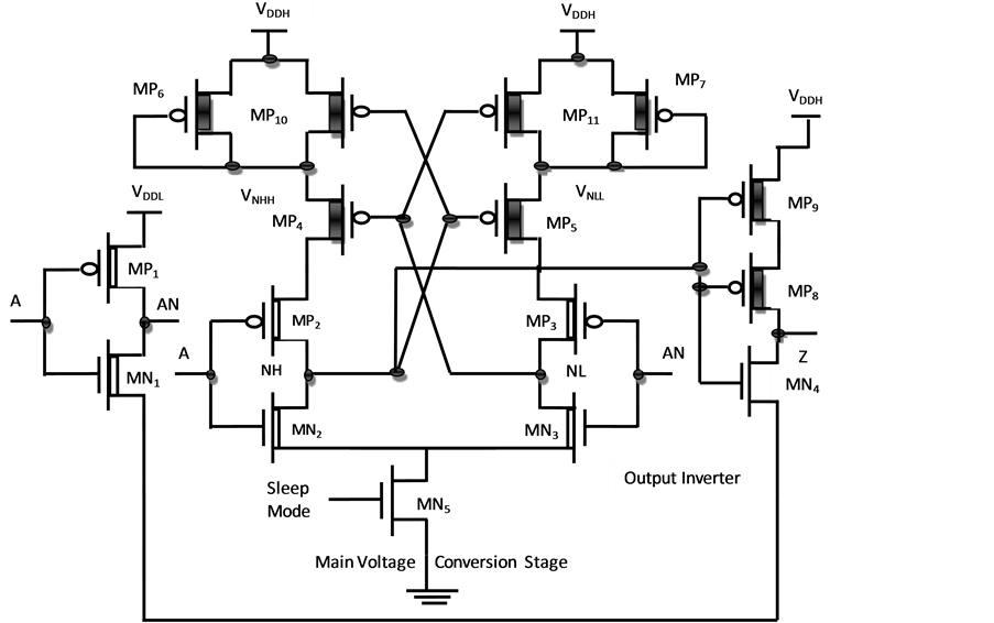
Figure 2. Proposed level shifter.
Table 2. Transistor sizing of proposed system.
3.6. Operation
As the input signal switches, the transistor MN2 is turned on and the node NH starts to be discharged. Due to this, the source to gate voltage of MP4 is reduced and increases its threshold voltage. Owing to this, MP4 is weakened, thus increasing the discharge of the node NH. In the meantime, the stronger pull-up of the right branch charges the node NL and causing MP4 to be turned off. This allows the discharging of NH to be further accelerated. As NH approaches the ground voltage, the positive feedback becomes to explode, causing MP5 to be fully activated. Therefore, NL is fully charged at the low voltage level. Once transitions in the nodes NH and NL are completed, the virtual power supplies VNHH = VDDH and VNLL = VDDH ? Vdsat, MP7 are established to provide fast switching in the subsequent input transition.
The used pull-up configuration allows static current when NH is high to be significantly reduced. In such a condition, the MP9 device has maintaining the source node of MP8 below VDDH. As the source terminal of MP8 results to be at lower voltage than its bulk node, the MP8 threshold voltage increases. The source-gate voltage of MP8 is also reduced, thus further reducing static current in the above condition. As 3 V external power supply is supplied to MN5 (sleep transistor) and it is always in turn on condition to block the leakage power from the main voltage conversion stage.
4. Implementation
4.1. Simulation Results
Figure 3 represents that simulation diagram of existing level shifter. In this diagram, appropriate nMOS and pMOS transistors are selected and then fix the width and length of the transistor and connected by using wire. High voltage nMOS transistor is used as a sleep transistor. Voltage pins are used to calculate the voltage conversion and wattmeter is used to calculate the power.
Figure 4 shows the waveform of voltage conversion and power analysis of proposed level shifter. PM1 denotes the power of 2.56 nW. VF1 denotes voltage converted to 1 V. VF2 denotes the voltage at NH. VF3 denotes the voltage at NL. VG1 denotes the voltage in sleep transistor.
4.2. Performance Analysis
Table 3 compares the existing system and proposed system. In both the systems, voltage conversion can be achieved from 100 mV to 1 V but low power can be achieved in proposed system than the existing system.
The Figure 5 shows that comparison chart of power analysis for existing and proposed system. The proposed system consumes 2.56 nW power. The existing system consumes 5.66 nW power. When compared to existing system, the proposed system consumes low power.
5. Conclusions
The proposed level shifter is suitable for robust logic voltage shifting from near/subthreshold to above-threshold domain. The proposed circuit exploits proper design strategies to maintain very low energy consumption and large voltage conversion range. Sleep transistor technique is used which is able to further reduce the total leakage power from the circuit to the ground by breaking the physical connection to the ground. And also low

Figure 3. Simulation diagram of proposed level shifter.

Figure 4. Output waveform of proposed level shifter.
Table 3. Comparison table of power analysis.

Figure 5. Comparison chart of power analysis.
power consumption can be achieved by proper sizing of transistor. The proposed design reliably converts 100 mV input voltage into 1 V output voltage. The simulation results demonstrate that the new LS shows power of 2.56 nW compared to existing system power of 5.66 nW.
The proposed level shifter is used in many applications. In future, the proposed level shifter is implemented in flip-flop circuit for further reducing the power and achieves the voltage conversion from subthreshold to above- threshold.
Acknowledgements
The authors are grateful to the Dean of Anna University, Regional Office-Madurai and management and principal of K.L.N. College of Engineering for providing all facilities for their research work.
Cite this paper
Raveendran Arun Prasath,Parasuraman Ganesh Kumar, (2016) Design of Low Power Level Shifter Circuit with Sleep Transistor Using MultiSupply Voltage Scheme. Circuits and Systems,07,1132-1139. doi: 10.4236/cs.2016.77097
References
- 1. Chang, I.J., Kim, J.J. and Roy, K. (2006) Robust Level Converter Design for Sub-Threshold Logic. ACM in Proceedings of the 2006 International Symposium on Low Power Electronics and Design, Tegernsee, 14-19 October 2006, 14-19.
http://dx.doi.org/10.1109/lpe.2006.4271800 - 2. Chavan, A. and MacDonald, E. (2008) Ultra Low Voltage Level Shifters to Interface Sub and Super Threshold Reconfigurable Logic Cells. 2008 IEEE Aerospace Conference, 1-8 March 2008, 1-6.
http://dx.doi.org/10.1109/AERO.2008.4526473 - 3. Chi, J.C., Lee, H.H., Tsai, S.H. and Chi, M.C. (2007) Gate Level Multiple Supply Voltage Assignment Algorithm for Power Optimization under Timing Constraint. IEEE Transactions on Very Large Scale Integration (VLSI) Systems, 15, 637-648.
http://dx.doi.org/10.1109/TVLSI.2007.898650 - 4. Clark, L.T., Deutscher, N., Demmons, S. and Ricci, F. (2002) Standby Power Management for a 0.18 μm Microprocessor. ACM in Proceedings of the 2002 International Symposium on Low Power Electronics and Design, 12-14 August 2002, 7-12.
http://dl.acm.org/citation.cfm?doid=566408.566413 - 5. Corsonello, P., Lanuzza, M. and Perri, S. (2014) Gate-Level Body Biasing Technique for High-Speed Sub-Threshold CMOS Logic Gates. International Journal of Circuit Theory and Applications, 42, 65-70.
http://dx.doi.org/10.1002/cta.1838 - 6. Ishihara, F., Sheikh, F. and Nikolic, B. (2004) Level Conversion for Dual-Supply Systems. IEEE Transactions on Very Large Scale Integration (VLSI) Systems, 12, 185-195.
http://dx.doi.org/10.1109/TVLSI.2003.821548 - 7. Hasanbegovic, A. and Aunet, S. (2009) Low-Power Subthreshold to above Threshold Level Shifter in 90 nm Process. IEEE in NORCHIP, Trondheim, 16-17 November 2009, 1-4.
http://dx.doi.org/10.1109/norchp.2009.5397793 - 8. Koo, K.H., Seo, J.H., Ko, M.L. and Kim, J.W. (2005) A New Level-Up Shifter for High Speed and Wide Range Interface in Ultra Deep Sub-Micron. IEEE International Symposium on Circuits and Systems, 23-26 May 2005, 1063-1065.
- 9. Lanuzza, M., Corsonello, P. and Perri, S. (2015) Fast and Wide Range Voltage Conversion in MultiSupply Voltage Designs. IEEE Transactions on Very Large Scale Integration (VLSI) Systems, 23, 388-391.
http://dx.doi.org/10.1109/TVLSI.2014.2308400 - 10. Lanuzza, M., Corsonello, P. and Perri, S. (2012) Low-Power Level Shifter for Multi-Supply Voltage Designs. IEEE Transactions on Circuits and Systems II, 59, 922-926.
http://dx.doi.org/10.1109/TCSII.2012.2231037 - 11. Lin, Y.S. and Sylvester, D.M. (2008) Single Stage Static Level Shifter Designs for Subthreshold to I/O Voltage Conversion. 2008 ACM/IEEE International Symposium on Low Power Electronics and Design (ISLPED), Banglore, 11-13 August 2008, 197-200.
- 12. Lütkemeier, S. and Rückert, U. (2010) A Subthreshold to Above-Threshold Level Shifter Comprising a Wilson Current Mirror. IEEE Transactions on Circuits and Systems II, 57, 721-724.
http://dx.doi.org/10.1109/TCSII.2010.2056110 - 13. Osaki, Y., Hirose, T., Kuroki, N. and Numa, M. (2012) A Low-Power Level Shifter with Logic Error Correction for Extremely Low-Voltage Digital CMOS LSIs. IEEE Journal of Solid-State Circuits, 47, 1776-1783.
http://dx.doi.org/10.1109/JSSC.2012.2191320 - 14. Shao, H. and Tsui, C.Y. (2007) A Robust, Input Voltage Adaptive and Low Energy Consumption Level Converter for Sub-Threshold Logic. 33rd European Solid State Circuits Conference, Munich, 11-13 September 2007, 312-315.
- 15. Soeleman, H., Roy, K. and Paul, B.C. (2001) Robust Subthreshold Logic for Ultra-Low Power Operation. IEEE Transactions on Very Large Scale Integration (VLSI) Systems, 9, 90-99.
http://dx.doi.org/10.1109/92.920822 - 16. Wang, W.T., Ker, M.D., Chiang, M.C. and Chen, C.H. (2001) Level Shifters for High-Speed 1 V to 3.3 V Interfaces in a 0.13 μm Cu-Interconnection/Low-k CMOS Technology. 2001 International Symposium on VLSI Technology, Systems, and Applications, Honolulu, 18-20 April 2001, 307-310.
- 17. Wooters, S.N., Calhoun, B.H. and Blalock, T.N. (2010) An Energy-Efficient Subthreshold Level Converter in 130-nm CMOS. IEEE Transactions on Circuits and Systems II, 57, 290-294.
http://dx.doi.org/10.1109/TCSII.2010.2043471 - 18. Yu, C.C., Wang, W.P. and Liu, B.D. (2001) A New Level Converter for Low-Power Applications. The 2001 IEEE International Symposium on Circuits and Systems, San Diego, 6-9 May 2001, 113-116.
- 19. Zhai, B., Pant, S., Nazhandali, L., Hanson, S., Olson, J., Reeves, A. and Blaauw, D. (2009) Energy-Efficient Subthreshold Processor Design. IEEE Transactions on Very Large Scale Integration (VLSI) Systems, 17, 1127-1137.
http://dx.doi.org/10.1109/TVLSI.2008.2007564 - 20. Prasath, R.A. and Kumar, P.G. (2015) A 8b 20MS/s 1.2 V Digital Ramp Asynchronous SAR ADC Using MTS Algorithm IN 0.13 nm CMOS Process. Journal of Revista Cientifica-Facultad De Ciencias Veterinarias, 25, 21-27.
http://www.cientificaonline.com/index.php/cientifica/article/view/726