Advances in Bioscience and Biotechnology
Vol.3 No.1(2012), Article ID:17191,6 pages DOI:10.4236/abb.2012.31007
Portable two linearly polarized beams absorption biometric system
![]()
Department of Electrical Engineering, Feng Chia University, Taichung, Taiwan
Email: kanatasan.tw@yahoo.com.tw
Received 10 October 2011; revised 12 November 2011; accepted 19 December 2011
Keywords: Collimated Beam; Transmitter; Receiver; Double Optical Path; Receiver
ABSTRACT
The purpose of this paper is to design a portable two linearly polarized beams absorption biometric system (PTLPBABS) that measures the amount of absorption of the visible collimated beam passing by the sample to know the absorbance of the sample. The measured object in the system is the gold colloid that the sample produces after a biochemical reaction. After measuring the absorbance of the gold colloid we can obtain the concentrations of the waiting-measured sample and further obtain the concentration of chemical solution contained in the sample. The two linearly polarized beams device can be used to enhance rejection of ambient light and causes PTLPBABS to have excellent data stability measured. The process of the double optical path method increases the opportunities that the visible collimated beam is absorbed, which raise the detection sensitivity of the system to a sensitivity of 0.1%.
1. INTRODUCTION
Using electro-optical techniques in a biometric system is an inevitable tendency as the technology evolves. A prime example of such a merger is the use of electrooptical device in the monitoring instantaneous singlet oxygen concentration produced during the treatment of cancer [1,2]. The absorption biometric system the author had previously developed and composed of a structure of single beam and double optical path distinguished from new one that has a different structure of two linearly polarized beam and double optical path contributing to more excellent measuring stability and dynamic testing. [3] The purpose of this research is to design a portable two polarized beams absorption biometric system which can be carried easily and has high sensitivity and absorbance stability measured. Optical and electro-optical characterization of substances includes reflectivity, selective absorption and electroluminescence. Different substances absorb different wavelengths of visible light, and this can be used to help to identify the substance, for example a particular functional groups in organic compounds. The amount of absorption is also dependent on the concentration of the substance if it is in solution. Measurement of the amount of absorption can be used to find concentrations of very dilute solutions. The system has four major parts. They are optical fiber unit, optical transmitter/receiver unit including transmitter and receiver, two linearly polarized beams and double optical path unit, and signal processing unit including data processing and display.
2. PRINCIPLE
The portable two linearly polarized beams absorption biometric system presented in this paper involves two principles. The first principle is the biological principle of Enzyme-linked immune sorbent assay (ELISA), the second principle is the electro-optical technique used in this system. Performing an ELISA involves at least one antibody with specificity for a particular antigen. The sample with an unknown amount of antigen is immobilized on a polystyrene micro-liter plate either non-specifically (via adsorption to the surface) or specifically (via capture by another antibody specific to the same antigen, in a “sandwich” ELISA). After the antigen is immobilized the detection antibody is added, forming a complex with the antigen. The detection antibody can be covalently linked to an enzyme, or can itself be detected by a secondary antibody which is linked to an enzyme through bioconjugation. The enzyme use in this system is the gold colloid, which has the property of light absorption. The system detects the intensity change of the visible collimated beam, which passes through the sample solution twice, to know the absorbance of the sample solution. The detective object of this system is the gold colloid that the sample produces after the biochemical reaction-immunology. There is a certain relationship between the color of the gold colloid and its concentration. By measuring the particular wavelength of the optical absorbance of the gold colloid, the concentration of the waiting measured sample can be obtained. The concentration of chemical compositions can be further obtained by establishing the relationship table between the optical absorbance of the gold colloid and the concentration of chemical compositions. From the Beer-Lambert law, the amount of radiation absorbed is represented in the follow equation: A = εbc, where A is absorbance since A = log10(p0/p); p0 is the beam of radiation entering the sample while p is the beam of radiation exiting the sample); ε is the molar absorptive with units of L·mol–1×cm–1; b is the path length of the sample-that is, the path length of the cuvette in which the sample is contained, we will express this measurement in centimeter; c is the concentration of the compound in the solution, expressed in mol×L–1. From above we can know that increasing the path length of the solution or increasing the monochromatic optical path in the waiting-measured sample solution can increase the optical absorbance. The processes of double optical path increase the opportunities that the collimated beam is absorbed which raise the detection sensitivity of this system. The method that allows the visible collimated beam to pass by the sample solution twice is the use of prism array.
3. THE PORTABLE TWO LINEARLY POLARIZED BEAMS ABSORPTION BIOMETRIC SYSTEM
The block diagram of PTLPBABS is shown in (Figure 1) The system includes: 1) optical fiber unit, 2) optical transmitter/receiver unit, 3) two linearly polarized beams and double optical path unit and 4) signal processing unit including data processing and display. The optical receiver unit has two receivers, one detects the light passing through the sample cell containing a solution of substance we are testing, and the other one detects the light passing through reference cell containing the pure solvent. The transmitter/receiver consists of LED light source, linear polarizer, photodiode, amplifier, filter, A/D converter, and comparator. The two linearly polarized beams and double optical path unit includes the two linearly polarized beams device and double optical path device. The double optical path device consists of beam splitter, collimated lens, cuvette and prism array as shown in (Figure 2).
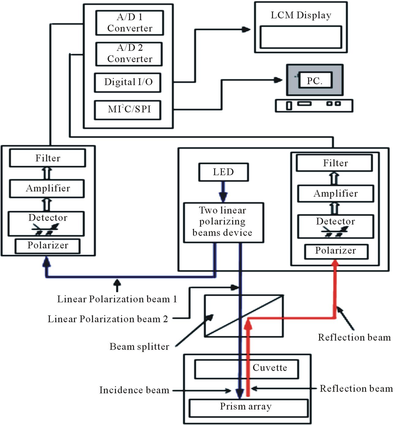
Figure 1. Block diagram of PTLPBABS configuration.
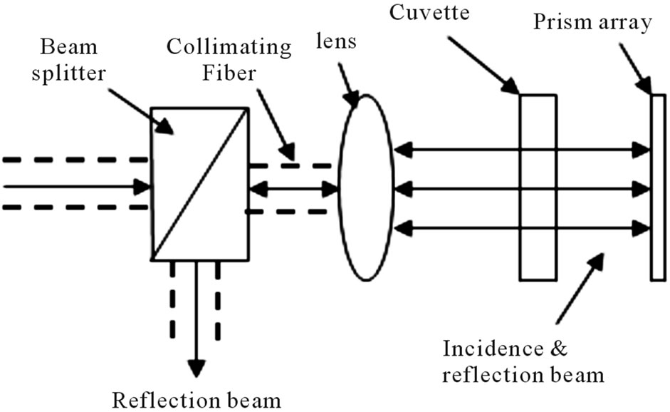
Figure 2. Double optical path device.
Increasing the path length of the sample increases the amount of samples needed resulting in increased testing cost. But sometimes we are absolutely not able to obtain so many samples. However, this defect can be improved by using the double optical path device.
The two linearly polarized beams device can split the incident nature light into two linearly polarized beams that consists of a Rochon polarizing prism and a half wave plate. Two linearly polarized beams have the same wavelength, the same phase and the same linear polarization state. Two linearly polarized beams from the two linearly polarized beams device have two optical characteristics that may be used to enhance rejection of ambient light; the first, it is a narrowband emission wavelengths of LED light matching with absorption’s wavelength of the gold colloid, and the emission spectrum of LED light is shown in (Figure 3). Therefore the system will block out a large majority of other ambient light. The second, it is polarization light-waves, which oriented in a specific direction. The linearly polarized beams from the two polarized beams device and linear polarizer in the receiver have the same polarization state so that they will block out half of all the randomly-polarized ambient light. Rochon polarizing prism consists of two birefringence quartz prisms; the first, cut parallel to the optic axis, receives the light; the second, with the optic axis at right angles, transmits the ordinary ray without deviation but the extraordinary ray is deflected.
A light beam is incident on the entrance face and is split into two orthogonally polarized beams by the Rochon prism, as shown in (Figure 4).In general, the wave plate is characterized by the amount of relative phase, Γ, that it imparts on the two polarized components, which is related to the birefringence Δn and the thickness L of the crystal by the formula Γ = [(2πΔnL)/λ0], where λ0 is the vacuum wavelength of the light.
For instance a half-wave plate (HWP) creates a halfwavelength phase shift and can change the polarization direction of linear polarized light. Suppose a plane-polarized wave is normally incident on a HWP, and the
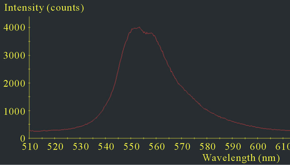
Figure 3. The emission spectrum of LED light.
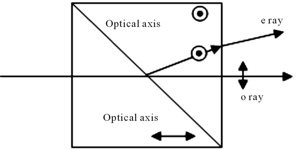
Figure 4. Rochon polarizing prism.
plane of polarization is at an angle θ with respect to the fast axis, as shown in (Figure 5). After passing through the plate, the original plane wave has been rotated through an angle 2θ. The half wave plate formed from two thin sections of crystalline quartz which have been cut to include the optic axis. The two sections are polished to different thicknesses in order to be having exactly the required retardation difference. They are then optically contacted with the axes opposed. In this way it is possible to provide precise retardation in a plate of usable thickness. Birefringence, or double refraction, is the decomposition of a ray of light into two rays when it passes through certain anisotropic materials, such as crystals of calcite as shown (Figure 4) [4-6].
One of the two rays does indeed obey Snell’s Law; this ray is called the ordinary ray (or e-ray). The other ray is an extraordinary ray (or e-ray). The difference between the indices of refraction of two ray can express Δn = ne − no. In (Figure 4), the incident beam goes first through the region whose optical axis is parallel to the plane of incidence. The two rays of light are each plane polarized by the anisotropic material such that the planes of polarization are mutually perpendicular. In the two linearly polarized beams device, the two linear polarized outgoing beams have the same wavelength, the same phase and the same linear polarization state. The prism array consists of many corner cube refractor. A corner cube reflector is a retroreflector consisting of three mutually perpendicular, intersecting flat surfaces, which
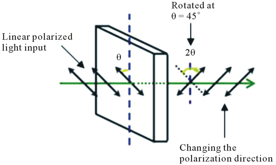
Figure 5. Half-wave plate.
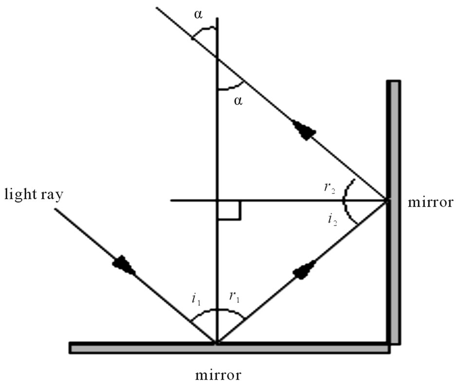
Figure 6. Corner cube refractor.
reflects parallel light ray back towards the source as shown (Figure 6).
A light ray incident from any direction in the plane perpendicular to both mirrors is reflected through 180˚.
We are effectively being asked to prove that α = i1, for any value of i1 from trigonometry and the law of reflection. The light emitting diode (LED) is used as the light source in the optical transmitter/receiver unit. The LED emits the green light which passes through the collimating lens and becomes a collimated beam. After this collimated beam passes through the sample, it will be reflected back by prism array, and pass through the sample again. The reflected beam is focalized by collective lens of the receiver and be detected by the photodiode. By using the collimated beam with the prism array, the system does not require a very sensitivity optical alignment. The system will also not suffer the effect of environment interference because of the use of pulse width modulation LED light and linear polarization light. The peak emission’s wavelength of the LED is matched with the peak absorption’s wavelength of the gold colloid. The advantages for using the LED over the general light source such as household tungsten lamp are the small size, short response time, long lifetime, stable performance, etc. Also, the cost of design for the driver circuit using LED is lower than that of the laser-diode. As the peak emission wavelength λp of LED has to be matched with the peak absorption wavelength λp of the sample, we use the peak emission wavelength of the green light of 550 nm as the light source in this optical-transmitter. LED is a kind of current-driven device, not a voltagedriven device. So, in order to generate stronger light beam for LED, we should provide larger forward bias current IF, but the light beam intensity is not proportional to the provided current. As the forward bias current IF becomes larger, the dark current also becomes larger. When IF becomes larger and larger, the LED will go into the saturation state, and then it will be burnt out. Also, if LED works under the larger current for a long time, it will becomes overheated and age too soon. To prevent LED from the aging problem, we use the pulsed current to drive LED, i.e. at the fixed duration, the constant current is provided. We use the inverter (CD4069) with the capacitors to form the multi-vibrating circuit. The pulse light output is 46 μsec pulse duration which is obtained with the LED driving circuit. The collimated beam of this device passes by the sample back and forth. Both the incident beam and the reflected beam are guided by the optical fiber. The reflected light will be focused on the detector by collective lens. The optical received terminal includes photodiode, filter circuit and amplifier. A potentiometer is placed before the filter circuit. By changing this, we can trim the sensitivity of the detector. To prevent the noise, such as the signal from the lighting lamp, from being amplified with the signal, we use a high pass filter comprised of capacitors and resistors to filter out the 120 Hz signal. Owing to the current generated by the photodiode is very small, and in order to be easily analyzed, we need to amplify the output voltage. The signal is amplified by using the amplifier LM324M and negative feedback. The ambient electric-magnetic interfereence (EMI) will affect the detection in the system. To prevent the EMI noise, we add a metal shield outside the circuit. The beam of the visible LED will be split into two beams. The first beam will go directly into the collimator to form the collimated beam. The collimated beam will pass through the samples, be reflected by the prism arrays to pass though the sample a second time before being finally detected by the photodiode. The other beam will go into the collimator, form collimated beam, and then be detected by the other photodiode without passing through the sample.
4. EXPERIMENT AND RESULTS
The conditions and specifications used for the experiment are listed in (Table 1). The diameter of the optical fiber used as the light guidance is 1.00 mm. The NA (numerical aperture) of multi-model plastic fiber is 0.44. The peak emission wavelength (λp) of LED is 550 nm and spectral bandwidth (∆λ) is 40 nm. The detector is silicon photodiode. The procedures of the experiment are stated below: 1) Reagent: free gold colloid solution is diluted by RO distilled water; 2) Using 500 micro-liter
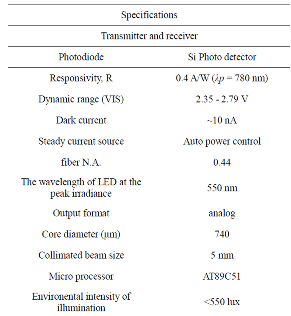

Table 1. The conditions and specifications of the experiment.
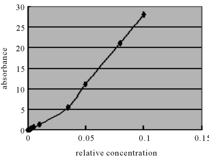
(μl) cuvette to load it, the effective optical path length of this solution is 5 mm; 3) the peak absorption wavelength of the free gold solution is located on the peak emission wavelength of LED. As in (Figure 7(a)), the result in this experiment reveals: if the concentration is above 10% or under 0.1%, there is no detected signal. The situation is shown as (Figure 7(b)) shows that the linear range is only from 0.1% to 1% of concentration. From this experiment, we can learn the following: sensitivity of this device is not only related to the design, but also related to 1) the quality of optical alignment of double optical path unit, and 2) the parallel and flatness of the front and back of the cuvette. The point in (Figure 7(b)) that has absorbance 0.6 and relative concentration 0.0055 is chosen as reference to measure the stability of PTLPBABS. The absorbance of the sample is tested 25 counts and the waiting time is an interval of 2 minutes between 2 counts. The experiment result is that the average absorbance is 0.602 and peak valley in absorbance is ±0.005 as shown in (Figure 8). The above results indicate that the two linearly polarized beams device can certainly enhance rejection of ambient light and cause PTLPBABS to have excellent data stability measured.
 (a)
(a)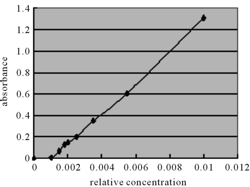 (b)
(b)
Figure 7. (a) Absorbance vs relative concentration; (b) Absorbance vs relative concentration.
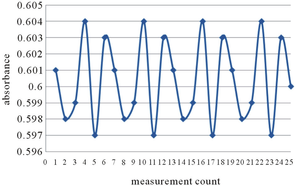
Figure 8. Measured value stability (25 counts, measuring time 50 minutes).
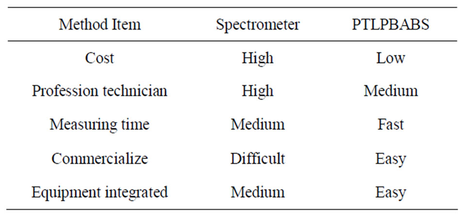
Table 2. The advantages of PTLPBABS.
5. CONCLUSIONS
From the results of the experiment, we see that the system achieved a sensitivity of 0.1%, which is a five fold increase over a single optical path system with sensitivity of 0.5%. The overall cost of the system is also signifycantly cheaper than a normal optical system that uses a spectrometer. The two linearly polarized beams device can certainly enhance rejection of ambient light and cause PTLPBABS to have excellent data stability measured. A normal spectrometer system has a wide variety of uses and consists of complex and costly circuitry to support the diversity of the system. However, by designing the system that is more focused on the particular task of absorption detection, resulting in elimination of a precision grating system, and the need of complex software. The reduction in the complexity and the reduction of the total amount of component in the system, the system have the additional benefit of reduced system size to that of one-fifth of a normal system. From now on, by changing its LED, we can detect different sample solutions without redesigning another detection circuit. Above all, it can be summarized in (Table 2).
6. ACKNOWLEDGEMENTS
This research was supported by National Science Council of Taiwan under contract No. NSC100-2623-E-035-001-D.
REFERENCES
- Dysart, J.S. and Patterson, M.S. (2005) Characterization of photofrin photobleaching for singlet oxygen dose estimation during photodynamic therapy of MLL cells in vitro. Physics in Medicine and Biology, 50, 2597-2616. doi:10.1088/0031-9155/50/11/011
- Chen, Q., Huang, Z., Chen, H., Shapiro, H., Beckers, J. and Hetzel, F.W. (2002) Improvement of tumor response by manipulation of tumor oxygenation during photodynamic therapy. Photochemistry and Photobiology, 76, 197- 203. doi:10.1562/0031-8655(2002)076<0197:IOTRBM>2.0.CO;2
- Chen, D.-C. (2008) Portable Biometric system of High sensitivity absorption detection. Journal of Microwave and Optical Technology Letters, 50, 868-871. doi:10.1002/mop.23249
- Berezhinsky, L.I., Berezhinsky, I.L., Pipa, V.I., Matyash, I.Y. and Serdega, B.K. (2007) Polarization analysis of birefringence in uniaxially deformed silicon crystals. Semiconductor Physics, Quantum Electronics & Optoelectronics, 10, 49-54.
- Van der Valk, N.C.J., Van der Marel, W.A.M. and Planken, P.C.M. (2005) Terahertz polarization imaging. Optics Letters, 30, 2802-2804. doi:10.1364/OL.30.002802
- Montarou, C.C and Gaylord, T.K. (1999), Analysis and design of modified Wollaston prisms. Optical Society of America, 38, 6604-6616.