Journal of Environmental Protection
Vol.5 No.2(2014), Article ID:43351,9 pages DOI:10.4236/jep.2014.52017
Multicriteria Assessment of Various Onsite Wastewater Treatment Options for Nigeria
1Department of Civil Engineering, University of Nigeria, Nsukka, Nigeria; 2Department of Civil Engineering, Akwa Ibom State University, Mkpat-Enin, Nigeria.
Email: chidozie.nnaji@unn.edu.ng
Copyright © 2014 Chidozie Charles Nnaji et al. This is an open access article distributed under the Creative Commons Attribution License, which permits unrestricted use, distribution, and reproduction in any medium, provided the original work is properly cited. In accordance of the Creative Commons Attribution License all Copyrights © 2014 are reserved for SCIRP and the owner of the intellectual property Chidozie Charles Nnaji et al. All Copyright © 2014 are guarded by law and by SCIRP as a guardian.
Received November 27th, 2013; revised December 26th, 2013; accepted January 25th, 2014
Keywords: Septic Tank; Wastewater; Contamination; Analytic Network Process; Risks
ABSTRACT
Eight onsite wastewater treatment systems (OWTS) were evaluated for suitability of application in Nigeria for efficient treatment and disposal of domestic wastewater, using analytic network process (ANP). Ten location related risks were used as criteria in the decision making process. Expert views were used to obtain pairwise comparison matrices of the OWTSs with respect to the criteria. Saaty’s Super Decision Software was used to complete the ranking process. The order of ranking obtained was as follows: septic tank with absorption field (0.1502) > septic tank with soakaway (0.142) > composting toilet (0.128) > septic tank with sand filter (0.125) > septic tank with constructed wetland (0.12) > septic tank with holding tank (0.12) > septic tank with mound system (0.118) > septic tank with recirculating sand filter (0.096). However, when the costs and life spans of these systems were incorporated into the ranks, and considering other factors, the septic tank with absorption field stood out as the best option. A simple sensitivity analysis shows that depth to water table, proximity to drinking water, susceptibility to flooding and proximity to large roots have the highest influence on the ranks of OWTSs.
1. Introduction
Onsite Wastewater Treatment System (OWTS) has gained more popularity in developing countries than the highly engineered centralised wastewater management system of industrialized nations due to some constraints including: lack of technical know-how, funds, mindset, lack of government involvement and commitment etc. [1,2]. Over the years, Nigerians have relied on OWTS for domestic water disposal. The septic tank system is the most widely used onsite treatment system for domestic wastewater. In fact, most developing countries (Nigeria inclusive) lack the technology and economic power to construct and operate sewerage systems for conveyance of domestic wastewater to central sewage treatment facilities, so a greater population relies on the septic tank system for sewage treatment. It is an enclosed receptacle designed to collect wastewater, segregate settleable and floatable solids (sludge and scum), accumulate, consolidate and store solids, digest organic matter and discharge treated effluent [3]. In the United States only, over 50 million people use the septic system [4]. However, recently, the development of mega cities such as Abuja has given rise to an upsurge of centralized wastewater treatment facilities. Huge amounts of capital have been invested in sanitation, infrastructure and services which are largely non-functional at the moment. This may be as a result of non-availability of spares parts for plant maintenance, funding problems and a myriad of problems [5]. In view of the above, it can be safely assumed that OWTS remains a viable solution to sanitation problems in developing countries. OWTS can be constructed and operated successfully almost anywhere because of its reliance on natural treatment processes unlike the centralised system that relies heavily on chemicals, equipment, and energy supply. In spite of the perception that onsite systems are inferior, old fashioned, technologically bankrupt, and not as safe as centralised system from an environmental and public health perspective, many communities have pursed the construction of the later (collection systems and sewage treatment plants). Centralised systems however are not the most cost effective or environmentally friendly option for all situations, as sewage treatment plants can discharge high point source loadings of pollutants into receiving waters. They are costly to build and operate especially in areas with low population densities and dispersed households. They can also contribute to eutrophication that might threaten water quality [2].
Anderson [6] stated that the factors affecting the performance of different OWTS include: effluent absorption rates; a percolation rate of between 20 and 90 minutes per inch is considered to be the acceptable range for good septic systems, proximity to surface water or wells; a minimum separation of 100 feet between drain fields and well is recommended, the septic system should be located on the portion of the building site where the risk is minimal, disturbance potential; which requires that systems should be located on portions devoid of tree-root damage, construction activities, or cars driving over drain fields, sizing requirements; which requires that systems be sized based on the anticipated usage, soil suitability is also of extreme importance amongst other factors. Any negligence of these factors exposes the OWTS to risk which results in total collapse of the system thereby endangering public health. In Nigeria, the ubiquitous septic tank with polishing soak away has failed in places with certain physiographic features such as high groundwater table, highly porous soils, high gradient soils, impermeable soil strata and swampy soils. This has resulted in indiscriminate fouling of groundwater and surface water, with concomitant outbreak and spread of epidemics. When septic tanks fail, they release nutrients and pathogens into the environment [7-9] such as groundwater, surface waters, swimming pools, farmlands etc. Jelliffe [10] reported septic tank failure rate as being higher than 40% in Australia. Of the 48 septic tanks studied by Ahmed et al. [11], 32(67%) needed cleaning out, 23(48%) had soggy absorption fields, 4(8%) had structural defects such as broken baffles or lids, 2(4%) had technical faults such as high water table or the absorption system being too close to a water well, 3(6%) had insufficient capacity, and only 7(15%) were well maintained. In order to circumvent the shortcomings of the conventional septic tanks other versions of OWTS have been developed over the years. Hence, this paper aims to rank different OWTS according to site suitability using Analytic Network Process (ANP) and create awareness on the need for careful selection of proper OWTS considering varying site conditions and the economic implications/justifications of selected systems.
2. Methodology
This research is a comparative study of variants of OWTS and their ranking according to suitability. This ranking is based on the different site criteria that may expose these systems to potential risks. These views are thus presented in overview form for decision-making.
2.1. An Overview of Selected OWTS
2.1.1. Septic Tank with Absorption Field Trench (STAFT)
A conventional absorption field trench also known as a rock lateral system, is the most common system used on level or land with moderate slope and adequate soil depth above the water table or some restrictive horizons. STAFT consists of a septic tank, distribution box, and a gravel filled absorption field installed below the soil surface [12]. Typically, household wastes are collected in the septic tank which retains the wastewater for approximately 24 hours, allowing the solids to separate and settle out. This also allows bacteria to partially decompose and liquefy the solids. A scum layer consisting of fats and oil floats on the surface of the wastewater. Sludge is retained in the septic tank and must be removed periodically. Effluent flows out of the septic tank to the distribution box where it is evenly distributed throughout the absorption filed. As the effluent moves through the soil, impurities and pathogens are removed by a combination of straining, adsorption, inactivation and decomposition.
2.1.2. Septic Tank with Soak Away (STS)
A septic tank is basically a vessel buried underground, the purpose of which is the collection, storage and to some limited extent, treatment of waste [13]. A typical septic tank system normally operates by gravity, and consists of a tank and soaks away drain. Soak away is a rectangular or circular excavation lined with geotextile fabric and filled with clean granular stone or other void forming materials that receive effluent from a perforated pipe inlet and allows it to infiltrate into the natural soil. Also referred to as a percolation trench, it is an underground soil treatment system, which receives partially treated sewage from the septic tank. Generally, a septic tank with soak away system performs two functions: it uses naturally occurring aerobic soil bacteria to further polish the pollutants in the effluent and disperse septic effluent into the soil.
2.1.3. Septic Tank with Holding Tank/Cesspool (STHC)
Cesspools/holding tanks are antiquated systems that receive waste from the house and allow the liquid portion to seep into the surrounding soil. Typically, they are cylindrical holes in deep soil, several feet in diameter. There is usually a porous inner wall of stone, masonry, precast concrete or other materials strong enough to shore up the soil [5]. The outer surface (between the concrete wall and outer soil wall) is filled with gravel. Raw wastewater flows into the top of the inner chamber which in turn, retains and partially digests the solids while the effluent seeps through to the gravel filled outer chamber, and then into the surrounding soil. Design of a cesspool depends upon the ability of the soil to absorb water, they should not be used in porous soil or where groundwater may come within 5 feet of the bottom. They should also be downhill and 500 feet away from wells used for drinking water. Because of the potential for direct, concentrated discharge of untreated waste to groundwater, cesspools are a high risk to public health and water quality.
2.1.4. Septic Tank with Sand Filter (STSF)
The STSF is ideal for soils with inadequate soil depth for wastewater filtration. The typical sand filter is a PVClined or concrete box filled with a specific sand material. A network of small diameter pipes is placed in a gravel-filled bed on top of the sand. The septic sand effluent is pumped under low pressure through the pipes in controlled doses to ensure uniform distribution. The effluent leaves the pipes, trickles downwards through the gravel and is treated as it filters through the sand. A gravel underdrain collects and moves the treated wastewater to either a second pump chamber for discharge to a pressure distribution drainfield or to a gravity flow drainfield. The second pump chamber may be located in the sand filter [14]. A typical sand filter system has 4 working parts: the septic tank, the pump chamber with a pump, the sand filter, and the disposal component including a drainfield (or possibly a mound) with its replacement area.
2.1.5. Septic Tank with Mound System (STMS)
Mounds were developed to overcome 3 natural conditions: slow or high permeable soils, shallow soils covered with porous bedrock, or high water table. The mound is a drainfield that is raised above the natural soil surface to achieve the desired vertical separation from a water table or impervious material on top of the best native soil stratum. At least 1 foot of naturally occurring soil is necessary for a mound system to function properly. The mound is composed of a sand fill that has gravel filled bed and a network of small diameter pipes known as the distribution system. From the chamber, effluent is pumped through the pipes in controlled, low pressure doses so that uniform distribution is achieved throughout the bed. The effluent comes out of the pipes through small holes and trickles downwards through the gravel bed and into the sand. Treatment of the effluent occurs as it moves through the sand and into natural soil [15,16]
2.1.6. Septic Tank with Rock-Plant Filter System (Constructed Wetland), (STRPF)
The rock-plant filter system, also called constructed wetland, is a term applied to a system designed to accomplish specific treatment tasks for wastewater, mimicking natural wetland. Wetlands which are natural purifiers in the environment are environments where plant roots are submerged in water or saturated soil all or most of the time [17]. Constructed wetland for individual home wastewater treatment includes: open wastewater surface with depths up to about 2 feet, wetland plants, lined rock beds with submerged wastewater flow, wetland plant root systems (rock-plant filter), unlined sand or gravel cells for additional treatment and absorption following either an open or submerged cell. The partially treated effluent from the septic tank enters the lined rock-plant filter cell through solid piping, where it is distributed across the cell. The plants within the system introduce oxygen into the wastewater through their roots, for aerobic digestion of organic matter. As the wastewater becomes oxygenated, beneficial micro organisms and fungi thrive on and around the roots, which leads to digestion of organic matter. In addition, large amounts of water are lost through evapotranspiration, and soil infiltration. Besides, the plants absorb some of the pollutants by osmotic pressure. All of the processes described above give rise to a substantially purified wastewater. Besides, due to the large amounts of water losses from the wetland, little or no effluent is produced.
2.1.7. Composting Toilet (CT)
A composting toilet is a well ventilated container that provides the optimum environment for unsaturated but moist human excrement for biological and physical decomposition under sanitary controlled aerobic conditions. It consists of a self-contained toilet with a chamber and venting system. The chamber contains sawdust and some water composting media which will combine with the waste material to form compost overtime. There are usually some methods to turn the pile to assure an even mixture and complete composting. Once composting is complete the residue is removed manually from the chamber. Completion of the process is recognised when satisfactory stabilization is attained. This is evidenced by the production of humus containing 2.3% Nitrogen, 1% - 1.5% P2O5 and K2O whereas chemical fertilizers are provided in a ration of 15:15:15 for NPK respectively [18,19]. It is worthy to note that a CT system encourages water efficiency (water is not wasted as a transport medium to flush toilets) and nutrients (nitrogen and phosphorous) are kept in tight biological cycles which may cause problems to receiving waters if left uncontrolled.
2.1.8. Septic Tank with Recirculating Sand Filter (STRSF)
A recirculating sand filter is a modified version of the sand filter. It was designed to alleviate the odour problems associated with open sand filter. Odour elimination occurs through recirculation, which increases the oxygen content in the effluent that is distributed on the filter bed [15]. The three basic components of an RSF system are a pretreatment unit, a recirculating tank, and an open sand filter. The recirculating tank is high in organic matter and low in oxygen, an environment ideal for denitrifying bacteria. Nitrates are converted to harmless nitrogen gas which is released to the atmosphere. RSFs are particularly good for treating wastewater where nitrate must be removed to protect the quality of groundwater or other water resources. They also provide a very good effluent water quality with over 95% removal of BOD and TSS.
2.2. Multicriteria Ranking Procedure
The Analytic Network Process, ANP was used because of its ability to capture the outcome of dependence and feedbacks within and between clusters of elements. The various steps involved in the multicriteria decision process as applied in this paper are given in the following subsections.
2.2.1. Model Construction And Problem Formulation
Here the goal of the study was stated. The section has two parts: first part is control hierarchy, consisting of network of relationship between goal, criteria and sub criteria. The goal is to rank various variants of OWTS in order of suitability or preference. Next is the criteria level which in this study consist of all the restrictive conditions affecting the siting of OWTS. The lowest and last level is the sub criteria level which consists of the alternative options OWTS viz: STS, STHC, STSF, STMS, STAFT, STRPF, CT and STRSF. Second part is creating network hierarchy, consisting of network of relationship between elements and clusters (Figure 1). It should be noted that the arrangement of elements at a particular level does not follow any order or preference.
Goal: Ranking of the OWTS Criteria: 1) Proximity to drinking water source, 2) proximity to flood zones, 3) siting in slope, 4) siting along property and building lines, 5) siting in parking areas, 6) proximity from roots of big trees, 7) proximity to pavings, building and drive ways, 8) seasonal and tidal water tables, 9) depth to bedrock, 10) effluent absorption rates; a total of ten criteria in all. It should be noted that most of the risks associated with OWTS are location dependent. Hence, all the criteria (risks) used in this study directly address location/siting of OWTS. OWTS proximity to drinking water sources such as wells, boreholes, ponds, springs and surface waters increase the risk of microbial contamination due to discharge of improperly treated wastewater. OWTS located in flood and tidal zones stand the risk of inundation and subsequent intermingling of freshwater with wastewater. The receding water is a mass of heavily contaminated water which then flows back into farmlands and surface waters. Siting OWTS in soils of high gradient can result in overland flow of wastewater from the system to adjoining soils, lawns, farmlands and any surface water bodies downstream. OWTS located along property lines, drive ways and parking lots are often subject to pressure from cars which can lead to the cracking of septic tanks. Roots of large trees can also penetrate the walls of septic tanks, generating big cracks as the roots increase in size. Cracked septic tank walls increase the risk of infiltration/
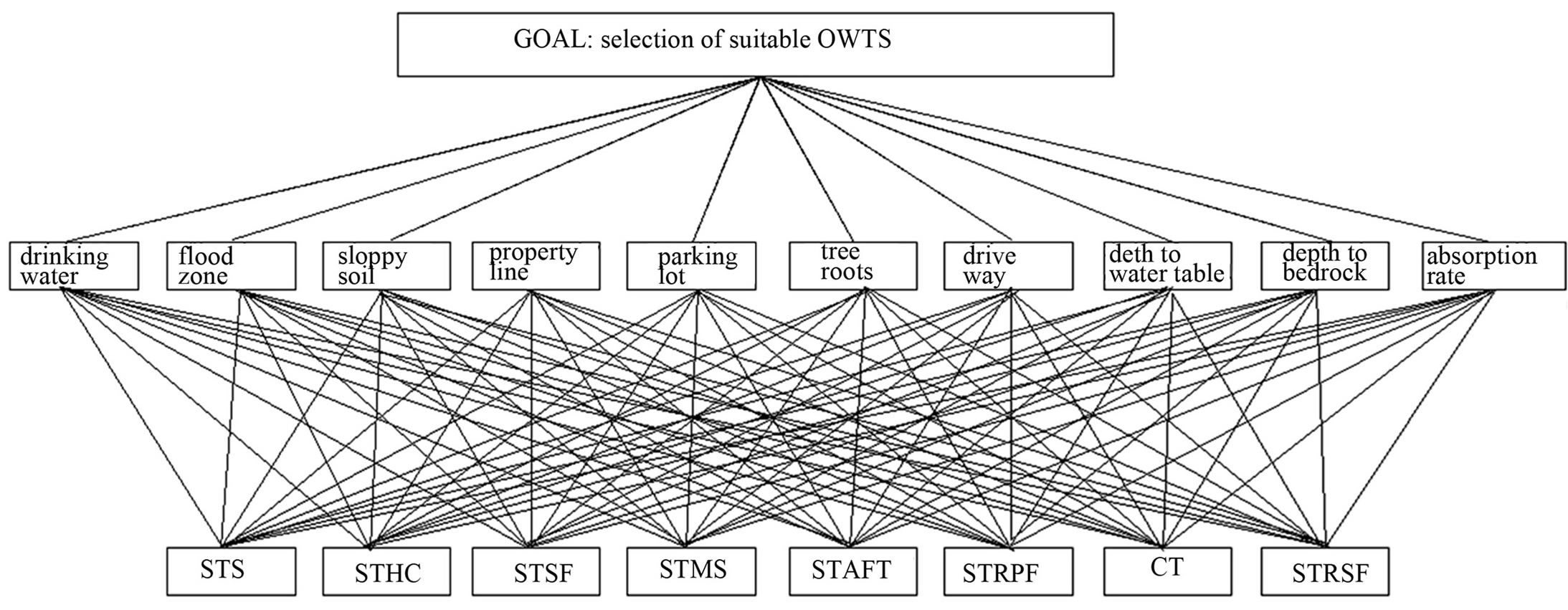
Figure 1. Problem formulation.
inflow and subsequent overloading of the system; and exfiltration which results in the discharge of untreated wastewater into groundwater. Areas with very little depth to bedrocks or very low infiltration rate are not suitable for OWTS. This is because of the absence of adequate soil for wastewater filtration as well as restricted infiltration rate. This usually leads to ponding and subsequent overland flow of wastewater. Also soils of high porosity allow for unregulated migration of microbes and nutrients to groundwater.
Sub-criteria: The subcriteria are the eight (8) variants of OWTS already discussed.
2.2.2. Questionnaire Surveys and Expert Preference Integration
According to the ANP model structure for decision issues, weightings were given to each element through questionnaires issued to experts to gather opinions regarding the respective importance of different criteria (risks) with respect to sub criteria (alternatives). For each of the criteria, the experts were asked to assign a weight (based on Saaty’s scale: 1 - 9) to each of the OWTS variants. The Saaty’s scale is defined as follows: Not risky 1); Minimal risk 2); Moderate risk 3); Moderate plus 4); Strong risk 5); Very strong risk 6); Very strong demonstrated risk 7); Very strong risk 8); Extremely risky 9). Averages were used to compute the collective weightings. Table 1 below shows the average view of experts with respect to the risk associated with each criterion for each OWTS.
2.2.3. Establishment of Pairwise Comparison Matrices and Vector Weights
Pairwise comparisons are made to determine the relative influence which the alternative has on the relative importance of the criteria. After the integration of judgments of experts, the comparison matrix of multiple valuation criteria and option were constructed. The pairwise comparison matrix A, in which the element aij of the matrix is the relative importance of the ith and jth alternatives with respect to criterion A is shown below such that aji is the inverse of aij.

where , and n is equal to the number of alternatives. Hence, there will be as many pair wise comparison matrices as there are criteria (10 in this case). The ten pairwise comparison matrices were computed from Table 1. To obtain the first pairwise comparison matrix, the first element of Table 1 was used to divide each of the elements of the first column. The resulting figures formed the first row of the matrix. The second element of the first column of Table 1 was again used to divide all the elements of the first column of Table 1. The resulting array of figures formed the second row of the pairwise comparison matrix. This step was repeated until all the elements of the first column of Table 1 have taken their turns in dividing all the elements of the first column. Thus the first pairwise comparison matrix was obtained. This matrix is a pairwise comparison matrix of the relative importance of the alternatives with respect to criteria 1. In order to obtain the remaining pairwise comparison matrices, all the columns of Table 1 were subjected to the same treatment as the first column. The vector weights of the alternatives with respect to each criterion were computed by entering the pairwise comparison matrices in Saaty’s Super decision Software. The result is given in Table 2 below.
2.2.4. Computation of Super Matrixes
To obtain global priorities in a system with interdependent influences, the super matrixes listed all sub matrixes consisting of all the sub matrixes, clusters and necessary elements in order on the left and upper sides of the matrix, each matrix segment represents a relationship between the two nodes (components or clusters) in the system. The un-weighted super matrix in this case is equal to the weighted super-matrix because we observed interdependence within one mode in carrying out the node design. The weighted super-matrix, W is as given in Table 3. In order to select the best alternative onsite wastewater treatment system, the limiting powers of the super-matrix were evaluated. This is given by Lim∑Wk. K is an arbitrary large number. This implies multiplying the super matrix by itself until it converges. Convergence is reached when all the elements of each row in the matrix become equal. However, in this study, the limit super

Table 1. Average views of experts with the unified ranks of the OWTS.
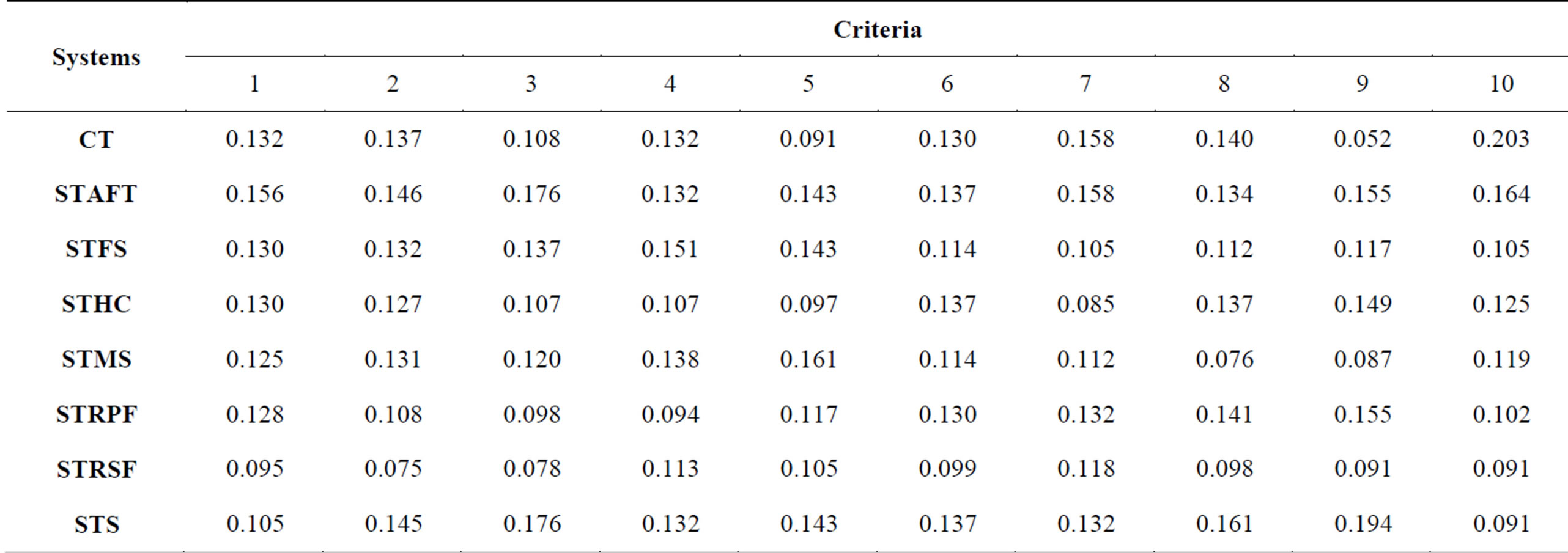
Table 2. Vector weights of alternatives with respect to criteria.
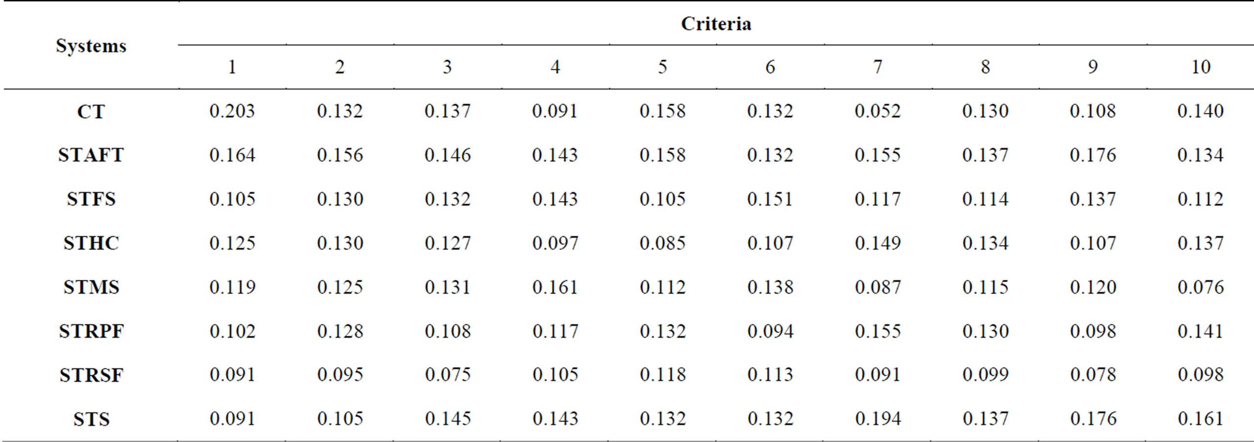
Table 3. Weighted super matrix.
matrix was computed using Saaty’s Super Decision Software. After synthesizing the limiting super matrix, the highest priority alternative was read off and it serves as the best option.
3. Results and Discussion
Ranking of the OWTS according to suitability follows the order in Table 4. The best alternative is the OWTS with the highest rank. Results obtained from the analysis show that the OWTSs were ranked in this order: STAFT > STS > CT > STSF > STRPF > STHC > STMS > STRSF. For ease of comparison, the ranks are shown pictorially in Figure 2. Ordinarily, one would expect that the more complex systems such as the STRSF, STMS and STRPF would have higher ranks than all the other OWTSs considered in this study, but this is clearly not the case. This is not to dispute their superior treatment efficiencies which were taken for granted in this study. The result of this study suggests that these systems should be used only in soils with highly restrictive characteristics and
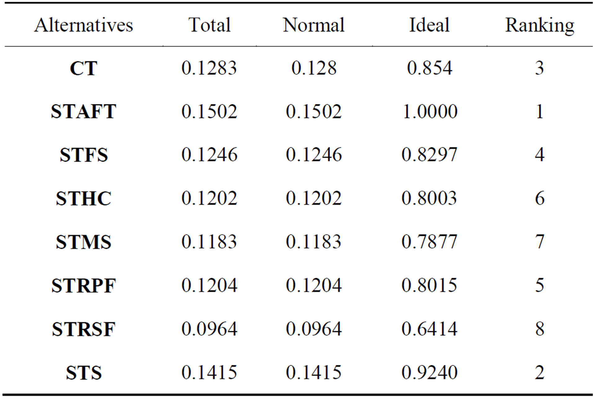
Table 4. Alternative rankings.
physiographic features. In such cases the order of preference should be as follows: STSF > STRPF > STMS > STRSF if finance is not a limiting factor. The STAFT and STS which ranked first and second respectively are currently the most common variants of OWTS used in Nigeria. Considering complexity, they are less complex
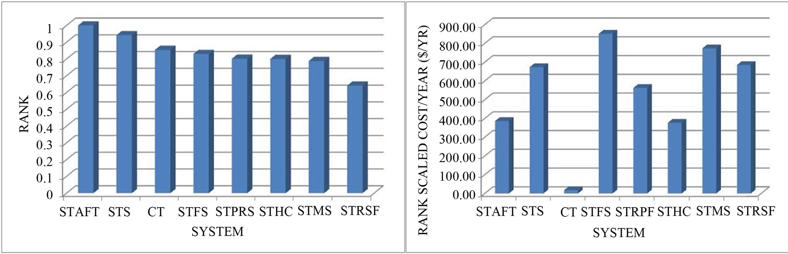
Figure 2. Ranks of OWTS.
and as such require less maintenance. The result of the raking was predominantly influenced by two factors viz: the type of criteria (risk) considered and the judgment of experts. However, the difference becomes more distinct when the costs and life spans of the different OWTSs are incorporated. This was achieved by scaling the ranks as follows: the ideal ranks of Table 4 were multiplied with the costs and divided with the life span (Figure 3). This operation yields a slightly different order of preference as follows: CT > STHC > STAFT > STRPF > STS > STRSF > STMS > STSF. The composting toilet which initially ranked third now ranks first on the scale of preference. The preference for the composting toilet stems from its environmental friendliness and a skew towards sustainability. Composting toilets do not require much water as a medium of transport and the fully stabilized waste serves as farm manure. This results in a highly reduced risk of groundwater contamination. However, despite the merits highlighted above, the minimal use of water as transport medium can translate to increased risk of disease transmission at the source of waste generation. The composting toilet is hardly found anywhere in Nigeria. Instead a variant of the composting toilet which is pit latrine is still used by the poorest people living in villages and slums because of its affordability. The septic tank with soakaway (STS) which previously ranked second now ranks fifth. The soakaway is a pit with porous walls into which septic tank effluent flows. The disadvantage of STS is that the soakaway grossly reduces the separation between the system on the one hand and groundwater table and bedrocks on the other. Adequate separation between OWTS and groundwater is a highly restrictive factor for their use. The septic tank with soil absorption field trench (STAFT), which consists of a septic tank followed by a soil absorption field, previously ranked first but now ranks third. The absorption field trench consists of series of perforated interconnected pipes for regulated distribution of septic tank effluent to the surrounding soil. The pipes are buried not too deep into the soil so that there remains enough soil depth for wastewater purification. This system is not commonly used in Nigeria possibly because this system requires a sizeable portion of land area which increases as soil absorption rate decreases. It however appears that the STAFT is the most appropriate for Nigeria and other developing countries both in terms of cost and all the other criteria considered in this study. For areas with restrictive soil features such as swampy areas and other areas with high groundwater level as are prevalent in the Niger Delta, the septic tank with rock-plant filter (STRPF) commonly referred to as constructed wetland followed by the septic tank with recirculating (STRSF) seem to be more appropriate. Constructed wetlands have the advantage of producing very minimal effluent as much water is lost by evapotranspiration. This certainly results in reduced groundwater contamination. For the sake of completeness, the cost and life span of each system has been given in Table 5.
Finally, it is instructive to briefly consider the influence of various risk on the ranks assigned to the different OWTSs. Table 6 shows that criterion 8 which represents depth to water table has the most influence on the ranking on OWTSs considered. The bold face figures in Table 4 indicate the criterion with the highest influence on a particular system; while the italicized bold face figures indicate the criterion with the least influence. Five of the OWTSs viz: STS, STHC, STPRF, CT and STRST are most influenced by depth to water table; while susceptibility of location to flooding mostly influenced the ranks of STSF and STMS. Only STAFT was mostly influenced by proximity to drinking water. On the other hand, proximity to driveway has the most influence on the ranks of STS, STHC and STSF; proximity to parking lot has the least influence on the ranks of STAFT and STPRF; depth to bedrock has the least influence on the rank of STMS and CT; absorption rate has the least influence on STRSF.
In order to ascertain the influence of the ten criteria/
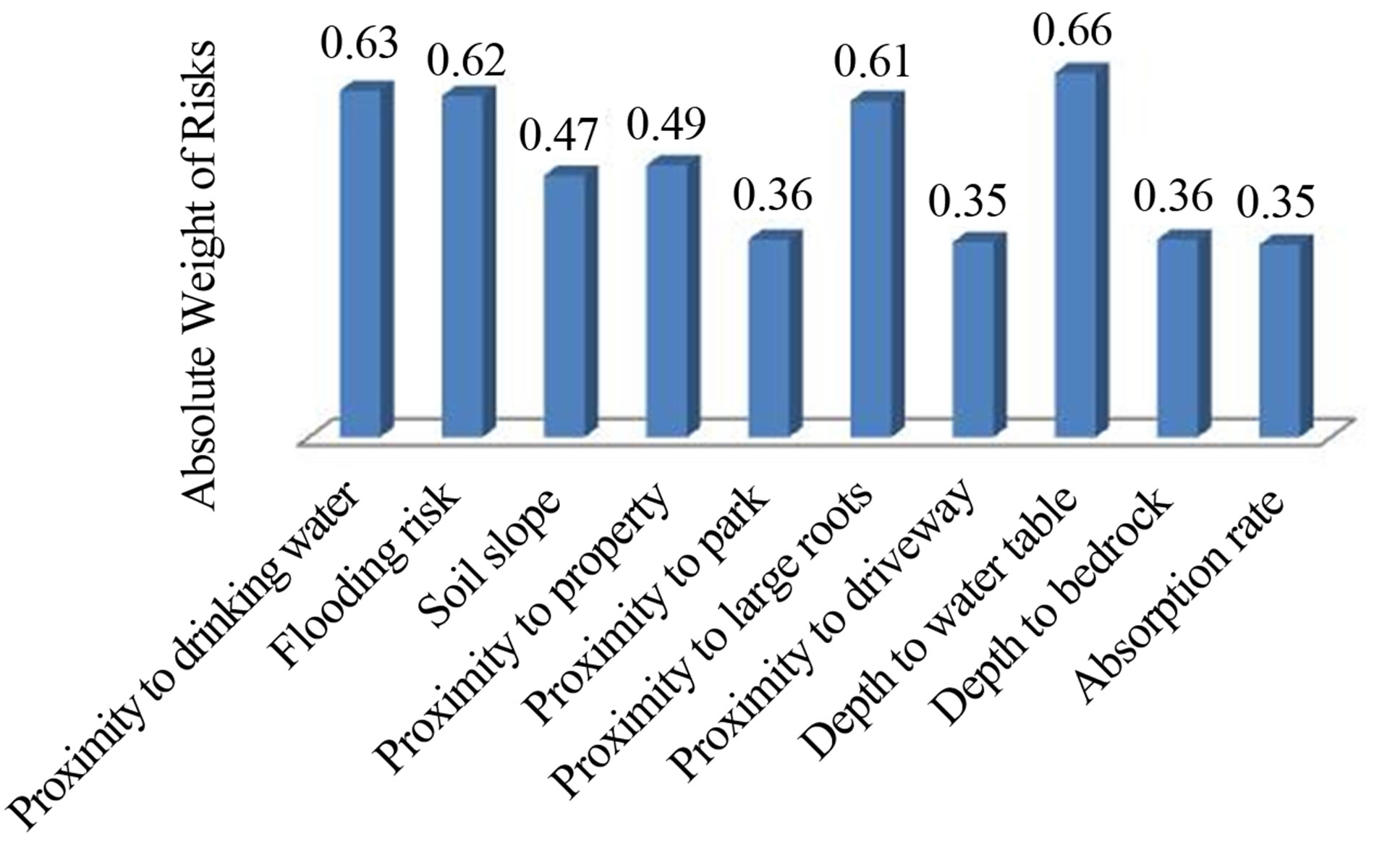
Figure 3. Absolute weights of various risks associated with OWTSs location.
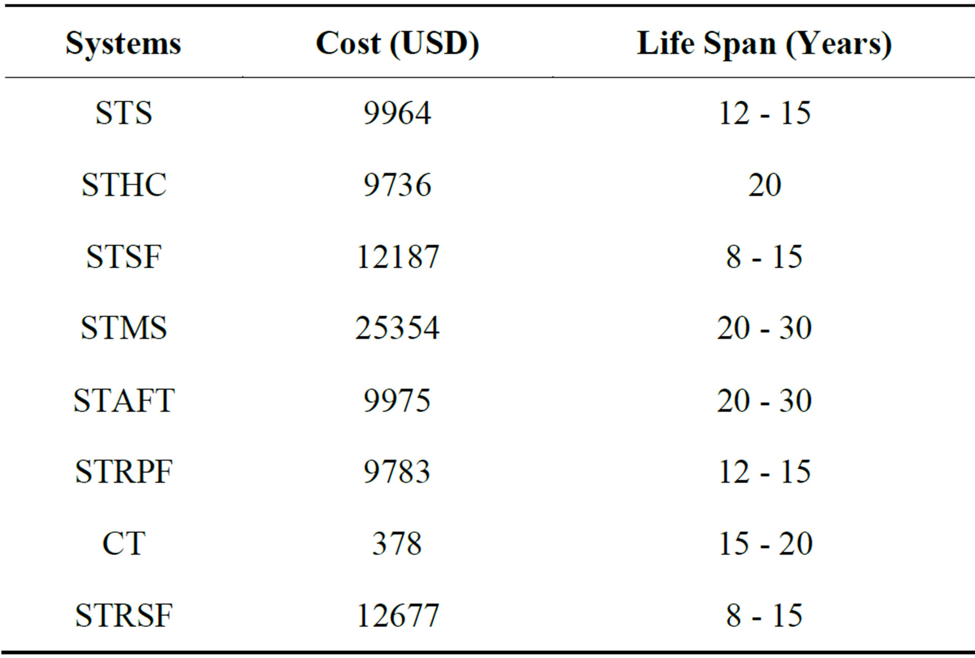
Table 5. Cost and life span summary of onsite systems.

Table 6. Percentage contribution of criteria to OWTS ranking (%).
risks on the overall ranking of the OWTSs, expert responses were transformed into absolute weight as represented by Figure 3. The absolute weights were estimated using Equation (1).
 (1)
(1)
The weights obtained show that depth to water table, proximity to drinking water, susceptibility to flooding and proximity to large roots have the highest absolute weights in that order. Hence, these factors must be given priority attention in OWTS selection as well as location of selected OWTS.
4. Conclusion
A careful selection of treatment system for onsite treatment of domestic wastewater is pertinent in order to reduce the spread of diseases originating from groundwater contamination. From this study, the septic tank with absorption field trench stands out as the best OWTS option in terms of safety, cost, simplicity and maintenance. OWTSs requiring the use of electricity such as the septic tank with mound system (STMS), septic tank with sand filter (STSF) and the septic tank with recirculating sand filter (STRSF) are not ideal because of the current dearth of electricity supply in the country. Constructed wetland is the next best option for areas with restrictive soil features such as high water table and shallow soils.
REFERENCES
- E. Omenka, “Improvement of Decentralized Wastewater Treatment in Asaba, Nigeria,” Master’s Thesis, Lund University, Lund, 2010.
- USEPA, “Draft Guidelines for Management of Onsite/ Decentralised Wastewater Systems,” Office of Wastewater Management, Washington DC, Federal Register, Vol. 65, No. 195, 2010, pp. 59840-59842.
- T. R. Bounds, “Design and Performance of Septic Tanks,” Conference of the American Society for Testing and Materials, Philadelphia, 1997.
- A. S. Collick, M. Z. Eaton, A. F. Montalto, B. Gao, Y. Kim, L. Day and S. T. Steenhuis, “Hydrological Evaluation of Septic Disposal Field Design in Sloping Terrain”, Journal of Environmental Engineering (ASCE), Vol. 132, No. 10, 2006, pp. 1289-1297. http://dx.doi.org/10.1061/(ASCE)0733-9372(2006)132:10(1289)
- S. Hoban, P. Troth, J. Ramsey, G. D. Mc Glothin and K. Nassar, “Onsite Wastewater Demonstration Project,” NAU College of Engineering and Technology, Flagstaff, AZ 86011-5600, 2012.
- D. L. Anderson, R. L. Siegrist and R. J. Otis, “Technology Assessment of Intermittent Sand Filters,” USEPA Municipal Environmental Research Laboratory, Cincinnati, 1989.
- P. M. Geary and E. A. Gardner, “Sustainable On-Site Treatment Systems, Individual and Small Community Sewage Systems,” American Society of Agricultural Engineers, St. Joseph, 1998.
- M. Yates, “Septic Tank Density and Groundwater Contamination,” Groundwater, Vol. 23, No. 5, 1985, pp. 586-591. http://dx.doi.org/10.1111/j.1745-6584.1985.tb01506.x
- M. R. Scalf, W. J. Dulap and J. P. Kreissel, “Environmental Effects of Septic Tank Systems,” US Environmental Protection Agency 18, EPA-600/3-77-096, 1977.
- P. A. Jelliffe, “Managing of On-Site Effluent Disposal: Conclusions from a Study on the Performance of 101 Systems in Maroochy Shire, Queensland, Australia,” Report Prepared for Maroochy Shire Council, 1995.
- W. Ahmed, R. Neller and M. Katouli, “Evidence of Septic System Failure Determined by a Bacterial Biochemical Fingerprinting Method,” Journal of Applied Microbiology, Vol. 98, No. 4, 2005, pp. 910-920. http://dx.doi.org/10.1111/j.1365-2672.2004.02522.x
- T. J. Bicki, “Septic Systems: Operation and Maintenance of On-site Sewage Disposal Systems,” Land and Water, No. 15, University of Illinois at Urbana-Champaign, 2011
- B. Gutterer, L. Sesse, T. Panzerbieter and T. Reckerzugel, “Decentralized Wastewater Treatment Systems (DEWATS) and Sanitation in Developing Countries: A Practical Guide,” Water Engineering and Development Centre, WEDC, London, 2009.
- Washington Department of Health, “Understanding and Caring for Your Sand-Filter System,” Publication No. 337-089, Wastewater Management Section, 2011.
- C. Solomon, P. Cassey, C. Mackne and A. Lake, “Recirculating Sand Filters,” Environmental Technology Initiative Factsheet, National Small Flows Clearinghouse Publishers, West Virginia University, 1998.
- P. Casey, S. Hagye, A. Lake, M. Kemp-Rye and K. Frame, “Mounds: A Septic System Alternative,” Environmental Technology Initiative Factsheet, National Small Flows Clearinghouse Publishers, West Virginia University, Vol. 10, No. 3, 1999.
- G. M. Powell, B. L. Dallemond and K. R. Manklin, “Rock-Plant Filter Design and Construction for Home Wastewater Systems,” MF-2340, Kansas State University, Manhattan, Kansas, 1998.
- USEPA, “Composting Toilet, Water Efficiency,” Technology Fact Sheet, EPA 832-F-99-066, Washington DC, 1999.
- J. C. Agunwamba, “Water Engineering and Management Tools,” Immaculate Publications Limited, Enugu, 2000.