Journal of Environmental Protection
Vol. 3 No. 8 (2012) , Article ID: 21761 , 8 pages DOI:10.4236/jep.2012.38088
Recycling of Glass Fibers from Fiberglass Polyester Waste Composite for the Manufacture of Glass-Ceramic Materials
![]()
1Centro Nacional de Investigaciones Metalúrgicas (CENIM-CSIC), Madrid, Spain; 2Instituto de Ciencias de la Construcción Eduardo Torroja (IETCC-CSIC), Madrid, Spain.
Email: *flopez@cenim.csic.es
Received May 6th, 2012; revised June 7th, 2012; accepted July 10th, 2012
Keywords: Valorisation; Waste Composite; Thermolysis; Gasification; Glass Fiber; Glass-Ceramic
ABSTRACT
This work presents the feasibility of reusing a glass fiber resulting from the thermolysis and gasification of waste composites to obtain glass-ceramic tiles. Polyester fiberglass (PFG) waste was treated at 550˚C for 3 h in a 9.6 dm3 thermolytic reactor. This process yielded an oil (≈24 wt%), a gas (≈8 wt%) and a solid residue (≈68 wt%). After the polymer has been removed, the solid residue is heated in air to oxidize residual char and remove surface contamination. The cleaning fibers were converted into glass-ceramic tile. A mixture consisting of 95 wt% of this solid residue and 5% Na2O was melted at 1450˚C to obtain a glass frit. Powder glass samples (<63 μm) was then sintered and crystallized at 1013˚C, leading to the formation of wollastonite-plagioclase glass-ceramic materials for architectural applications. Thermal stability and crystallization mechanism have been studied by differential thermal analysis. Mineralogy analyses of the glass-ceramic materials were carried out using X-ray Diffraction.
1. Introduction
The sustainable elimination of composites still remains as a challenge nowadays. On one hand, global production of composites materials increases every year, and it is expected to reach 10.3 Mt in 2015. Of all these composites, about 90% corresponds to thermostable composites with glass fibers (fiberglass reinforced plastics (FGRP)). The recycling of these composites is not, at present, profitable in economic terms, because obtained fibers present lower mechanical properties than the original ones, and cannot be employed in the manufacture of structural materials. Therefore, most of the waste glass fiber composites are stored in landfills or buried. This arises serious environmental problems, due to this kind of wastes are usually non-biodegradable and very bulky.
In absence of specific legislation in the EU, these wastes are often apply the European Directive on End-of Life Vehicles (1999/31/EC, 2000/53/EC) [1,2] and the European Directive on Waste Electrical and Electronic Electronic Equipment, (WEEE), (2002/96/EC) [3]. These legislations limit the amount of waste that may be set aside for landfills. Besides, UK and Germany has implemented a total ban for the dumping of this waste.
Recycling composites is difficult since they typically contain two or more components (filler, fiber, resin, etc.). Recycling thermoset composites is a particular challenge since, once the thermoset matrix molecules are crosslinked, the resulting material can no longer be remelted or remoulded [4]. Further, the most common thermosetting resins, such as polyester and epoxy resin, cannot be depolymerised to their original constituents [5]. Thermoset composites therefore commonly end up in landfills, and since the components are nonbiodegradable, the economic costs of such disposal can be very high.
A number of technologies have been proposed for recycling thermoset composites:
1) Mechanical comminution-based processes to obtain a specific grain size that renders the material useful as reinforcement in new formulations [6-8].
2) Thermal processing such as:
a) Combustion and the use of the heat generated [9, 10].
b) Pyrolysis [11] and thermolysis [12].
c) Fluidised bed thermal processes to recover the carbon fiber reinforcement from composites [13,14].
3) Composite depolymerisation based on chemical processes such as hydrolysis, glycolysis and solvolysis to recover organic materials [15].
The glass fibers obtained as a solid residue in pyrolysis suffer the degradation of their physical properties, limiting their reuse [5,14]. Nonetheless, the residual glass fiber was used in the manufacture of new composites with no important decline in the mechanical properties of the final product [16,17]. None of these techniques achieves more than the partial recovery of glass fiber and packing.
This work proposes the reuse of glass fiber in the production of glass-ceramic materials. Glass-ceramics are polycrystalline materials of fine microstructure that are produced by the controlled crystallisation (devitrification) of a glass. The first glass-ceramics, developed in the 1950s, were produced via a conventional glass-making process, followed by crystallisation involving heating and later cooling (allowing nucleation and crystallisation respectively). In recent years, however, the sintering method has become a technologically viable route of glass-ceramics manufacture. Sintered glass-ceramics are usually made by milling a glass frit into particles of adequate size, heating to provide sintering, and then allowing crystallisation of glass particles.
Glass-ceramics have found a wide variety of applications in different technological fields [18]. The most important glass-ceramic for architectural applications is Neoparies®. This wollastonite material is produced on a large scale for building interior and exterior walls. Large flat or curved sheets of this material can also be produced for facing buildings. The main properties of Neoparies® include great resistance to weathering, zero water absorption rate, hardness (which is greater than that of natural stone), light weight (30% lighter than natural stone building materials), and the ease with which curved panels can be made [19].
This paper evaluates the valorisation of waste composites by a thermolysis and gasification process and the suitability of the glass fiber as alternative raw materials in the manufacture of wollastonite-plagioclase glassceramic material for architectural applications. The thermolysis process basically involves pyrolysis the waste composite at high temperature (typically 550˚C) in the very little oxygen present (<3 vol.%) this prevents combustion reactions taking place to decompose the polymer matrix into oil, char and gas. After the polymer has been removed, the fibers are heated in air to oxidize residual char and remove surface contamination. The fibers are then recovered for reuse via glass-ceramic material.
2. Experimental
The polyester fiberglass (PFG) waste (Polifibra S.A., Guadalajara, Spain) used in this work was composed of E-glass fiber (SiO2: 54.3 wt%, Al2O3: 15.2 wt%, CaO: 17.2 wt%, MgO: 4.7 wt%, B2O3: 8.0 wt%) plus unsaturated polyester resin made from orthophtalic acid and styrene. Table 1 shows the composition of PFG waste.
The total amount of organic matter contained in such PFG waste, deduced from Table 1, is 35.5 wt%.
The elemental composition of the PFG waste was determined using an automated LECO CHNS 923 analyser (Table 2) [20].
The thermal behavior of the PFG samples (particle size = 100 - 200 µm) was studied using a Setaram Sensys Evolution 1500 thermal analysis system equipped with a differential thermal analyser (DTA) and a thermogravimetric analyser (TGA). The samples were heated at 800˚C at heating rates of 10˚C·min−1 in pure air (20 ml·min−1).
PFG was treated at 550˚C for 3 h in a 9.6 dm3 thermolytic reactor, which consists of a heating system and a gas condensation device. Temperature of 550˚C was selected as the working temperature based on preliminary studies. The experiment was performed in triplicate. This process of thermolysis yielded a solid residue, oil and a non-condensed gas [20]. The amount of gas generated was estimated by the difference between the initial weight of PFG and the amount of liquids and solids obtained.
The solid residue obtained in thermolysis was oxidized in air atmosphere. After thermolysis, pressurized air was injected into the reactor (20 l/h) maintaining the temperature at 550˚C. The final result is a glass fiber without organic matter. The recovering of weight in glass fiber during gasification stage was calculated by using Equation (1):
 (1)
(1)
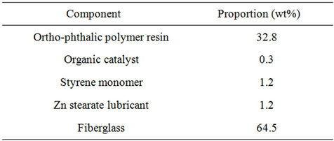
Table 1. Composition of the PGF waste used in the experiments.
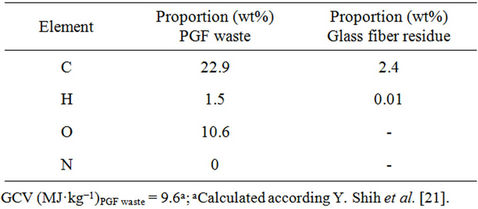
Table 2. Elemental composition and gross calorific value (GCV) of the PGF waste and the glass fiber residue obtained by thermolysis.
where  is the yield (mass) of the solid residue obtained during thermolysis,
  is the mass loss during gasification and
  is the glass fiber content of the initial PGF waste (see Table 1).
Elemental analyses of the solid residue obtained in the thermolysis process were undertaken using a LECO TGA 701 and LECO CHNS 923 analyser respectively. Morphological studies of the post-thermolysis solid residue (char-covered glass fibers) were performed using a Hitachi model S-2100 scanning electron microscope (SEM). Samples were coated in graphite for observation. The clean glass fibers recovered after gasification were gold plated and examined using a Jeol JSM 6500 F field emission microscope (FEM). Fiber diameter was determined according to British Standard ISO 11567 [22].
Tensile tests were performed on individual fiber glass filaments. The fibers were extracted by carefully pulling them with standard tweezers and then glued onto a cardboard frame with an epoxy adhesive (Araldit), the glue was allowed to cure for a day. The frame consist of a small thin rectangle about 1 mm by 8 mm, with a small rectangle cut from the middle about 0.5 mm by 4 mm. The cardboard frame was fixed to the grips of a microelectro-mechanical testing machine for the tensile tests (Kammrath & Weiss’ Tensile/Compression Stage). After cutting the cardboard sides, the load was immediately exerted on the fiber and the tensile test carried out under stroke control at a cross head speed of 2 µm per minute. The load carried by the fibers was measured with the 500 mN load cell of the testing machine while the fiber elongation was determined directly with the cross-head displacement and, therefore, including the elastic compliance of the load system. This method, as the opposite to measure the actual cross-section of each individual fiber, is specially suited for fibers whose diameter distribution is fairly constant as in this case [23]. The Young’s modulus of the fiber glass filament was also calculated.
The clean glass fiber recovered after gasification was ground using a BIOMETAL RETSCH PM 100 ball mill at 500 rpm for 15 min. A glass was formulated with incorporation 5% of Na2O to facilitate the melting process.
The components (204.25 g of the resulting powder (particle size < 250 µm) and 18.4 g of Na2O (as Na2CO3) were mixed for 30 minutes in a blender (TURBULA) to get a homogeneous mixture. The batch was placed in an aluminosilicate crucible and heated at 10˚C·min−1 in an electric furnace up to 1450˚C. After a holding time of 120 min at the melting temperature, the melt was quenched by pouring into water producing a glass frit. This frit was then ground using a BIOMETAL RETSCH PM 100 ball mill at 400 rpm, and several fractions of different sized particles separated (see Table 3) with the aim of determining the effect of particle size on glass crystallisation.
The thermal stability of these different glass fractions and their preferential crystallisation mechanisms (surface or bulk) were studied by DTA employing a SETARAM LABSYS TG apparatus. DTA analyses were performed between 25˚C and 1400˚C in air, using calcined Al2O3 as a reference material. All analyses were performed at a heating rate of 50˚C·min−1. The DTA curves were normalised to sample weight. The evaluation of the amorphous nature of glass after melting and the mineralogical study of the crystalline phases devitrified after thermal treatment was performed by X-ray diffraction (XRD) (Philips model X’PERT MPD) with Ni-filtered Cu Kα radiation operating at 30 mA and 50 kV.
The feasibility of the sintering + crystallization process to produce glass-ceramic tiles was evaluated on a mixture of different particle size glass powders: 1600 - 2000 µm, 160 - 250 µm and 80 - 100 µm and on glass powder with particle size of 80 - 100 µm. The percentages of the different fractions (1600 - 2000 µm (42 wt%), 160 - 250 µm (34 wt%) and 80 - 100 µm (24 wt%)) and 80 - 100 µm (100 wt%) respectively, were randomly chosen. The samples were compacted by vibration in a plaster mould and afterward fired at 1013˚C for 60 minutes with heating and cooling rate of 50˚C·min−1.
3. Results and Discussion
Figure 1 shows the TG/DTG curves for the thermal degradation of PFG waste in air. The first phase (dehydration) temperature peak occurs at around 210˚C (mass loss = 1.8 wt%). The second and main phase of degradation temperature peak occurs between 259˚C and 392˚C (mass loss = 26.4 wt%). In the isophthalic acid-based polyester resin the second step involves scission at the cross-link and formation of styrene and the linear poly
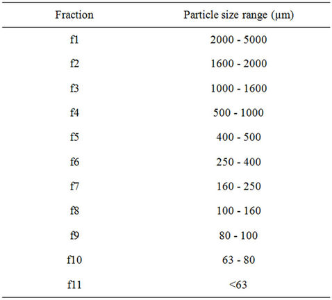
Table 3. Different particle size ranges.
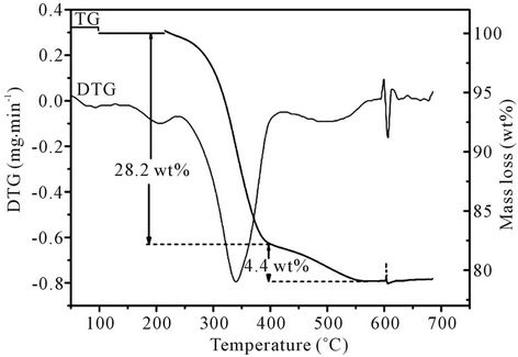
Figure 1. TG/DTG curves for PFG waste when thermally degraded in air.
ester which subsequently breaks randomly [24,25]. The third phase (gasification of char) peak occurs at around 449˚C (mass loss = 4.4 wt%). The formation of char is due to secondary repolymerization reactions among the polymer derived products. The total mass loss over the temperature interval 20˚C - 800˚C was 32.6 wt%.
The process of thermolysis yielded a solid residue, an oil and a gas. The yield of solid residue was 68.1 wt% ± 0.8 wt%; the oil and non-condensed gas fractions accounted for 23.9 wt% ± 0.1 wt% and 8.0 wt% ± 0.9 wt% respectively. The liquid + gas yield (31.9 wt% ± 0.8 wt%). The thermolysis solid residue was essentially composed of 96 wt% glass fiber and 4 wt% char. During gasification a weight loss of 4.0 wt% ± 0.2 wt%, coherent with the obtained by DTA/TG tests, was obtained. Applying Equation (1), the recovering of weight in glass fiber is 99.4 wt%. Table 4 shows the yields (wt%) of final products obtained after thermolysis and gasification processes.
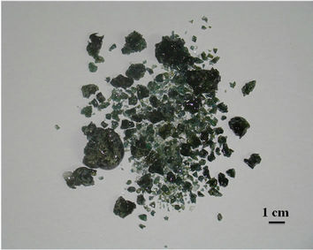
Figure 2(b) shows the solid residue obtained by thermolysis. This residue was composed of pieces of dimensions equal to those of the input material (Figure 2(a)), but completely black. Figure 2(c) shows the glass fiber obtained after gasification process. It is noted that the fiber is completely free of carbonaceous material or char.
Figure 3 shows the microstructure of the initial waste composite (a) and the glass fiber after thermolysis at 550˚C (b) and the glass fiber after gasification. Char (in Figure 2(b)) can be seen on the surface of the fibers. It has been reported [5,13,16] that a certain amount of char or coke-like material is formed during the pyrolysis of many polymeric materials due to secondary repolymerisation reactions in the gaseous phase. Figure 3(c) shows glass fibers after gasification process. The mean diameter of fibers is about 19.8 µm.
The response of the fiber was linear an elastic up to the final catastrophic fracture (Figure 4). The maximum load attained was used to compute the strength of each individual fiber from the average cross-section area given
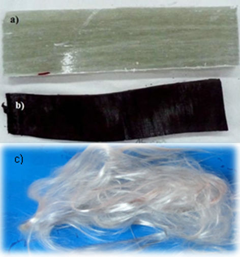
Figure 2. (a) PFG waste fragment (5 × 15 cms); (b) Glass fiber residue after thermolysis (≈5 × 15 cms); (c) Cleaning glass fibers after gasification.
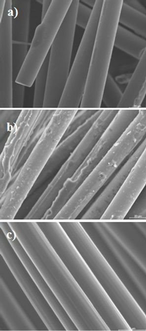
Figure 3. SEM photographs of fibers: (a) In the waste composite; (b) After the process of thermolysis; and (c) After gasification process.
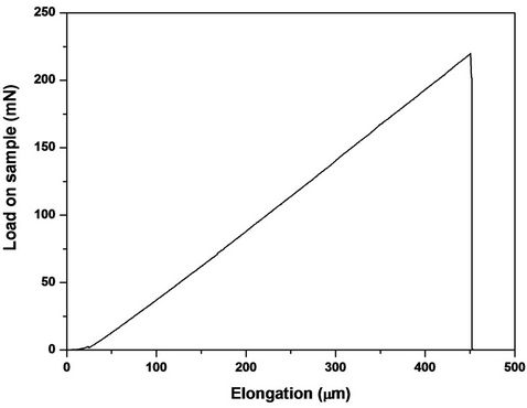
Figure 4. Load-elongation curve of the filament of cleaning glass fiber.
in Table 5.
The elongation at break (Figure 4) has an average value of 467 ± 92 microns. The strength of the pristine fiber given by the manufacturer was also included in the table for comparison purposes. However their mechaniccal strength is reduced by the high temperature needed to decompose the matrix. The fibers obtained after thermolysis and gasification process, have a tensile strength of ≈618 MPa, which means a decrease in resistance of between 80% - 84% of the value of virgin fiber strength. The elastic Young modulus of the glass filament is not affected significantly by the pyrolysis and gasification treatment. The fiber diameter barely modified compareed to the virgin fiber diameter. The decrease in tensile strength of glass fibers recovered using processes of pyrolysis, has been previously described by other authors. Kennerley et al. [26] and Pickering et al. [27] show decreases in tensile strength of between 50% - 90% of glass fibers recovered by heating waste of various composites content E-glass fiber in a fluidized bed, at temperatures between 450˚C - 650˚C. Recently, Feih et al. [28] have reported that at the temperatures used in conventional thermal recycling processes (above 450˚C), the strength loss for single fibers and fiber bundles exceeds 40% and 80%, respectively.
Figure 5 illustrates the appearance (a) and the amorphous nature (b) of glass after melting (or glass frit). The glass shows X-ray diffraction patterns characteristic of amorphous materials.
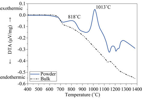
Figure 6 depicts the DTA curves of both powdered (<63 µm) and bulk glass produced from the glass after melting, and for the different size fractions.
As expected, both curves (Figure 6(a)) show a glass transition temperature, Tg, at 672˚C, because this temperature is independent of glass particle size and it is just related to glass composition and to the cooling rate from
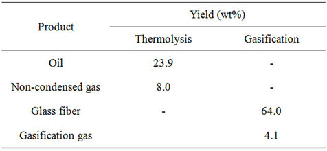
Table 4. Thermolysis and gasification yields (wt%).

Table 5. Fiber diameter, strength and Young’s modulus of individual fibers.
 (a)
(a)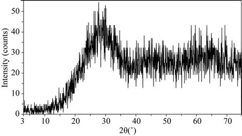 (b)
(b)
Figure 5. (a) Appearance of glass after melting; (b) X-ray diffraction patterns for the glass.
melting temperature. After Tg, two exothermic effects centred at 818˚C and 1013˚C respectively denotes that glass fiber residue is unstable on heating and thus, subsequent thermal treatment will lead to a crystallization process with the consequent formation of glass-ceramic materials. Finally, two endothermic reactions starting at
 (a)
(a)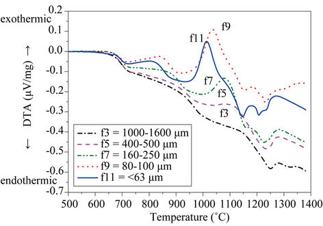 (b)
(b)
Figure 6. DTA curves of (a) powdered glass (<63 µm) (b) and bulk glass.
≈1100˚C indicates the formation of liquid phases. On the contrary, DTA curve recorded on bulk glass sample shows no exothermic peaks, indicating that bulk glass is thermally stable and crystallization by heating does not occur. This behaviour indicates that after subsequent thermal treatments, the glass will devitrify through a surface crystallization mechanism and therefore, the most appropriate method for glass-ceramic materials production will be through a sintering + crystallization process.
To assess the effect of particle size on crystallization, Figure 6(b) shows the DTA curves recorded on the different particle size fractions (Table 3).
To facilitate the observation, only selected fractions have been depicted. It is noted that increasing particle size leads to a decrease in the height of crystallization peaks, which even disappear from the curve recorded on 1000 - 1600 µm fraction. The exothermic peak centered at 818˚C is undetectable in fractions with particle size larger than 100 µm, whereas crystallization peak at 1013˚C is not perceptible for particles above 1000 µm. Consequently, DTA curves recorded on particles larger than 1000 µm do not show any exothermic peak, indicating that these fractions are very stable against crystallization. These results verify that surface crystallization plays a major role in crystallization of the present glass.
Figure 7 shows the X-ray diffractogram of the glassceramics produced after thermal treatment at 1013˚C for 60 min.
Glass devitrification leads to a glass-ceramic material composed of wollastonite (CaSiO3) and plagioclase s.s., which corresponds to a series of solid solution between albite (NaAlSi3O8) and anorthite (CaAl2Si2O8) endmembers. These results confirm that surface crystallisation plays a major role in the formation of the glass-ceramic. Similar findings have been reported for other materials [30-32].
Figure 8 illustrates the appearance the glass-ceramic tiles obtained by sintering + crystallization of mixtures of glass powders of different particle sizes at 1013˚C for 60 min: (a) 1600 - 2000 µm, 160 - 250 µm and 80 - 100 µm, (b) 80 - 100 µm.
It is noted that the glass particles reach an appropriate degree of sintering during heating, resulting in a compact tile. Glass grains with particle size lower than 250 µm crystallize during firing and give rise to an opaque ceramic material, whose crystalline phases scatter visible light (a, b). By contrast, larger glass particles (>1600 µm) are thermally stable and therefore, maintain a high degree of transparency (a). The combination of matt crystalline region and transparent amorphous grains results in a glass-ceramic material with an aesthetic similar to natural stone. It appears that it could be suitable as ceramic tile for wall covering or floor pavement. Therefore, by varying the relative percentage of fractions of different particle size would be possible tiles with different aesthetics.
Currently, the determination of the technological properties of these materials is being carried out in order to know their performance to be used in building applications.
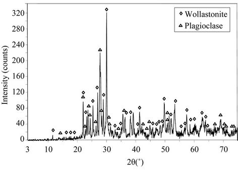
Figure 7. X-ray diffraction patterns of the glass-ceramics produced after thermal treatment at 1013˚C/60 min.
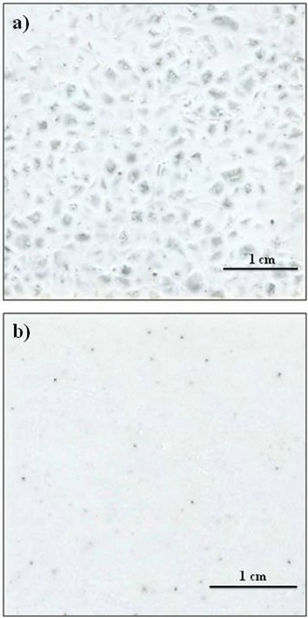
Figure 8. Appearence of the glass-ceramic tiles obtained from mixtures of glass particles with different size after sintering-cristallization treatments at 1013˚C for 60 min: (a) 1600 - 2000 µm, 160 - 250 µm and 80 - 100 µm; (b) 80 - 100 µm.
4. Conclusions
The thermolysis is a highly suitable method for recovering valuable products and energy from PFG. This process resulted in 68 wt% solid residue, the liquid (oil) and gas fractions accounted for 24 wt% and 8.0 wt% respectively. The solid residue consisted of 96 wt% glass fiber and 4 wt% carbonaceous material. The solid residue was oxidezed in air atmosphere, obtaining a glass fiber free of organic matter. The recovering of glass fiber in the combined process thermolysis-gasification was 99%. The cleaning glass fiber was successfully recycled by a vitrification process. The glass devitrify through a surface crystallization mechanism because the crystallization depends of particle size (particle size fractions larger than 1000 µm are very stable to crystallization). The crystalline phases identified in the glass-ceramic materials obtained were wollastonite and plagioclase s.s.
Compact glass-ceramic tiles can be produced from the powder glass through a sintering + crystallisation method. By varying the relative percentage of the different particle size fractions, tiles with different aesthetic qualities might be designed.
The novel thermolytic and vitrification processes described in this work hold promise for recycling fiberglass-reinforced composite materials.
5. Acknowledgements
Dr. M. I. Martín expresses her gratitude to the Spanish National Research Council (CSIC) for her contract through the JAE Program (JAEDoc-08-00032), co-financed by the European Social Fund.
Dr. I. García acknowledged for the contract JAEDoc_09-00893 (CSIC), Co-funded under the FSE Operational Programme 2007-2013 Adaptability and Employment Multiregional.
REFERENCES
- Council Directive, “1999/31/EC on the Landfill of Waste,” Official Journal of the European Union, Vol. L182, 1999, pp. 1-19.
- Council Directive, “2000/53/EC on End of Life Vehicles,” Official Journal of the European Union, Vol. L269, 2000, pp. 34-42.
- Council Directive, “2002/96/EC of Waste Electrical and Electrical Equipment (WEEE),” Official Journal of the European Union, Vol. L37, 2003, pp. 24-38.
- R. De Rosa, E. Telfeyan, G. Gaustad and S. Mayes, “Strength and Microscopic Investigation of Unsaturated Polyester BMC Reinforced with SMC-Recyclate,” Journal of Thermoplastic Composite Materials, Vol. 18, No. 4, 2005, pp. 333-349. doi:10.1177/0892705705049560
- S. J. Pickering, “Recycling Technologies for Thermoset Composite Materials-Current Status,” Composites Part A, Vol. 37, No. 8, 2006, pp. 1206-1215.
- T. Inot, T. Yokoi, K. I. Sekiyama, N. Kawamura and Y. Mishima, “SMC Recycling Technology,” Journal of Thermoplastic Composite Materials, Vol. 7, No. 1, 1994, pp. 42-55. doi:10.1177/089270579400700104
- A. K. Bledzki and K. Goracy, “The Use of Recycled Fiber Composites as Reinforcement for Thermosets,” Mechanics of Composite Materials, Vol. 29, No. 4, 1993, pp. 352-356. doi:10.1007/BF00617160
- B. Sims and C. A. Booth, “Process for Separating Fibers from Composite Materials,” International Patent WO 93/05883, Phoenix Fiberglass, Inc., 1993.
- S. J. Pickering and M. Benson, “Recovery of Materials and Energy from Thermosetting Plastics,” Proceedings of 6th European Composite Materials Conference on Recycling Concepts and Procedures, Bordeaux, September 1993, pp. 41-46.
- E. Schmidl and S. Hinrichs, “Method for Disposing Glass-Fiber-Reinforced Components Such as Rotor Blades of Wind Turbines with a Main Body Made of Fiber-Reinforced Plastics, Comprises Supplying the Rotor Blades to a Clinker Production Process as an Alternative Fuel More Options,” Patent Number: WO 2010148418- A1, Holcim Technology Ltd., 2010.
- S. J. Evans, P. J. Haines and G. A. Skinner, “PyrolysisGas-Chromatographic Study of a Series of Polyester Thermosets,” Journal of Analytical and Applied Pyrolysis, Vol. 55, No. 1, 2000, pp. 13-28.
- F. A. López, T. A. Centeno, F. J. Alguacil and B. Lobato, “Distillation of Granulated Scrap Tires in a Pilot Plant,” Journal of Hazardous Materials, Vol. 190, No. 1-3, 2011, pp. 285-292.
- Y. Zheng, Z, Shen, S. Ma, C. Cai, X. Zhao and Y. Xing, “A Novel Approach to Recycling of Glass Fibers from Nonmetal Materials of Waste Printed Circuit Boards,” Journal of Hazardous Materials, Vol. 170, 2009, pp. 978- 982.
- S. J. Pickering, R. M. Kelly, J. R. Kennerley and C. D. Rudd, “A Fluidized Bed Process for the Recovery of Glass Fires from Scrap Thermoset Composites,” Composites Science and Technology, Vol. 60, No. 4, 2000, pp. 509-523.
- T. Iwaya, S. Tokuno, M. Sasaki, M. Goto and K. Shibata, “Recycling of Fiber Reinforced Plastics Using Depolymerization by Solvothermal Reaction with Catalyst,” Journal of Materials Science, Vol. 43, No. 7, 2008, pp. 2452-2456.
- G. Jie, L. Ying-Shun and L. Mai-Xi, “Product Characterization of Waste Printed Circuit Board by Pyrolysis,” Journal of Analytical and Applied Pyrolysis, Vol. 83, No. 2, 2008, pp. 185-189.
- A. Torres, I. de Marco, B. M. Caballero, M. F. Laresgoiti and G. Kondra, “Recycling of the Solid Residue Obtained from the Pyrolysis of Fibreglass Polyester Sheet Molding Compound,” Advanced Polymer Technology, Vol. 28, No. 2, 2009, pp. 141-149. doi:10.1002/adv.20150
- T. Manfredini, G. C. Pellacani and J. M. Rincón, “GlassCeramic Materials Fundamentals and Applications,” Mucchi Editore, Módena, 1997.
- http://www.webmineral.com/data/Nepheline.shtml
- F. A. López, M. I. Martín, F. J. Alguacil, J. M. Rincón, T. A. Centeno and M. Romero, “Thermolysis of Fibreglass Polyester Composite and Reutilisation of the Glass Fibre Residue to Obtain a Glass-Ceramic Material,” Journal of Analytical and Applied Pyrolysis, Vol. 93, 2012, pp. 104- 112.
- Y. Shih, R. Jeng and K. Wei, “Carbon Black Containing Interpenetrating Polymer Networks Based on Saturated Polyester/Epoxy III: Thermal and Pyrolysis Analysis,” Journal of Analytical and Applied Pyrolysis, Vol. 70, 2003, pp. 129-142.
- British Standard ISO 11567:1995, “Carbon Fibre,” Determination of Filament Diameter and Cross-Sectional Area, 1995.
- E. Kandare, B. K. Kandola, D. Price, S. Nazaré and R. A. Horrocks, “Study of the Thermal Decomposition of Flame-Retarded Unsaturated Polyester Resin by Thermogravimetric Analysis and Py-GC/MS,” Polymer Degradation and Stability, Vol. 93, No. 11, 2008, pp. 1996- 2006. doi:10.1016/j.polymdegradstab.2008.03.032
- L. Tibiletti, C. Longuet, L. Ferry, P. Coutelen, A. Mas, J. J. Robin and J. M. López-Cuesta, “Thermal Degradation and Fire Behavior of Unsaturated Polyester Filled with Metallic Oxides,” Polymer Degradation and Stability, Vol. 96, No. 1, 2011, pp. 67-75.
- J. B. Hurst, W. S. Hong, M. L. Gambone and J. R. Poerter, “ASTM Single Fibre Room Temperature Test Standard Development,” International Gas Turbine & Aeroengine Congress & Exhibition, Paper 98-GT-567, American Society of Mechanical Engineers, 1998.
- J. R. Kennerley, R. M. Kelly, N. J. Fenwick, S. J. Pickering and C. D. Rudd, “The Characterization and Reuse of Glass Fibres Recycled from Scrap Composites by the Action of a Fluidized Bed Process,” Composites Part A, Vol. 29, No. 7, 1998, pp. 839-845. doi:10.1016/S1359-835X(98)00008-6
- S. J. Pickering, R. M. Kelly, J. R. Kennerley and C. D. Rudd, “A Fluidised Bed Process for the Recovery of Glass Fibres from Scrap Thermoset Composites,” Composites Science and Technology, Vol. 60, No. 4, 2000, pp. 509-523. doi:10.1016/S0266-3538(99)00154-2
- S. Feih, E. Boiocchi, G. Matys, Z. Mathys, A. G. Gibson and A. P. Mouritz, “Mechanical Properties of ThermallyTreated and Recycled Glass Fibres,” Composites Part B, Vol. 42, No. 3, 2011, pp. 350-358.
- F. T. Wallenberger and P. A. Bingham, “Fiberglass and Glass Technology: Energy-Friendly Compositions and Applications,” Springer, New York, 2010.
- M. Romero, M. Kovacova and J. M. Rincón, “Effect of Particle Size on Kinetics Crystallization of an Iron-Rich Glass,” Journal of Materials Science, Vol. 43, 2008, pp. 4135-4142.
- S. Teixeira, J. M. Rincón and M. Romero, “Crystallization of SiO2-CaO-Na2O Glass Using Sugarcane Bagasse Ash (SCBA) as Silica Source,” Journal of the American Ceramic Society, Vol. 93, No. 2, 2010, pp. 450-455.
- M. I. Martín, J. M. Rincón, M. Romero, F. Andreola, L. Barbieri, F. Bondioliy and I. Lancellotti, “Materiales Vitrocerámicos del Sistema MgO-Al2O3-SiO2 a Partir de Ceniza de Cáscara de Arroz,” Boletin de la Sociedad Espanoda de Ceramica Vidrio, Vol. 50, No. 4, 2011, pp. 201-206.
NOTES
*Corresponding author.