World Journal of Mechanics
Vol. 3 No. 3 (2013) , Article ID: 32874 , 8 pages DOI:10.4236/wjm.2013.33019
A New Rectangular Finite Element Formulation Based on Higher Order Displacement Theory for Thick and Thin Composite and Sandwich Plates
1Shaktibad Apartment, Phase-2, Ground Floor, Garia Station Road, Calcutta, India
2Department of Mechanical Engineering, Institute of Structural Mechanics, Technical University of Darmstadt, Darmstadt, Germany
Email: goswami_sanjib@hotmail.com, *becker@fsm.tu-darmstadt.de
Copyright © 2013 Sanjib Goswami, Wilfried Becker. This is an open access article distributed under the Creative Commons Attribution License, which permits unrestricted use, distribution, and reproduction in any medium, provided the original work is properly cited.
Received December 6, 2012; revised April 9, 2013; accepted April 17, 2013
Keywords: Finite Element; Displacement Approach; Plate Bending; Composite; Shear Deformation; Higher Order Theory; Lock-Free
ABSTRACT
A new displacement based higher order element has been formulated that is ideally suitable for shear deformable composite and sandwich plates. Suitable functions for displacements and rotations for each node have been selected so that the element shows rapid convergence, an excellent response against transverse shear loading and requires no shear correction factors. It is completely lock-free and behaves extremely well for thin to thick plates. To make the element rapidly convergent and to capture warping effects for composites, higher order displacement terms in the displacement kinematics have been considered for each node. The element has eleven degrees of freedom per node. Shear deformation has also been considered in the formulation by taking into account shear strains ( and
and ) as nodal unknowns. The element is very simple to formulate and could be coded up in research software. A small Fortran code has been developed to implement the element and various examples of isotropic and composite plates have been analyzed to show the effectiveness of the element.
1. Introduction
Development of plate bending elements dates long back in the history of finite element method itself. The first developments were based on thin plate theory (Kirchhoff’s plate theory), which neglects the effects of transverse shear deformation on bending. A challenge then is the slope continuity requirement ( continuity) that is not easy to fulfill in many physical situations. So a lot of research works have been directed to the development of elements based on Reissner-Mindlin plate theory [1,2]. The advantage of this approach is the independence of transverse deformation and rotations and therefore only
  continuity is required at the nodes. Reissner-Mindlin theory accommodates shear deformation in plate bending elements that is highly suitable for moderately thick and thin plates. However, elements with low order polynomial expressions formed on the basis of Reissner-Mindlin theory tend to lock in thin plate situations (shear locking). This problem can be handled with reduced/ selective integration as described in the well known text book of Zienkiewicz et al. [3]; though spurious zero energy modes may arise in some cases. A mixed approach can be used as an alternative to the selective technique. Elaborate presentations of element development by direct displacement method and isoparametric concepts can be found in the book of Zienkiewicz & Taylor [3] in a complete and step by step manner with enough references at the end of each chapter. A large body of analytical results on isotropic plates and shells has been presented in Timoshenko and Krieger [4]. This is the first attempt to present the solutions of plates and shells equations in a systematic manner and served as a historical document and monograph of thin walled structures. Results have been presented in parametric forms that can be verified by the finite element community very easily and the book has practical importance in industry as well.
Research works of Whitney [5] and Pagano [6-8] have clearly shown that the thickness concept, as it is known for isotropic plates, is completely different for heterogeneous plates. For such plates, the distortion of the deformed normal due to transverse shear is dependent, not only on the laminate thickness, but also on the orientation and degree of orthotropy of the individual layers. Thus for a general finite element intended to be applied to composite structures, the incorporation of the effects of transverse shear deformation in the formulation is important. A comprehensive analytical study for static and dynamic analysis of plates has been provided by Dobbyns [9].
Considerable efforts have been made to develop robust finite elements in plate bending [3]. Most of the isoparametric elements [3] have shear deformation included in the formulation, but require reduced integration to alleviate shear locking. But by employing reduced integration, spurious mechanisms have been created that in some cases provide unrealistic deformations. Displacement based elements using polynomials have been developed [10] for arches, plates and shells. A displacement based triangular element has been proposed by Sheikh and Dey [11]. The approach is based on displacements and only isotropic plates are considered. Another rectangular element has been proposed by Engblom & Ochoa [12] in a well written work. The element has been applied to crossply composite plates and found to be working well. Guenfoud [13] used DSTM & DKTM elements to find the structural response of plate structures. Both the elements (DKTM, DSTM) are based on Discrete Kirchhoff Triangle concept, applied to linear thin plates without any shear deformation and uncoupled membrane-bending action. The other attractive elements are based on compatibility of strain approach [14]. Attempts have also been made to develop elements with shear deformation for composite plates [15-20]. It is shown in some works [15,16,18,20,21] that the numerical computation using isoparametric elements has its limitations, that might lock in thin plate situations. A large volume of literature is available for element technology on plate bending applications. A complete literature review is beyond the scope of this study. Interested readers are directed to several well written review papers [22-24] for a more complete treatment of this topic. A comparatively recent review paper on the finite element applications on laminated composite plated structures has been presented by Zhang and Yang [25].
In the current work an attempt has been made to develop a shear deformable rectangular element for thick to thin plates. The suggested element is based on a polynomial displacement approach (non-isoparametric). The polynomials for all nodal unknowns have been taken in a judicious manner to ensure monotonous and rapid convergence. The plate kinematics incorporating higher order terms ensure a good convergence rate and capture cross-sectional warping of laminates which is essential for thick plates. On the other hand, some extremely thin plate conditions have been handled as well successfully which indicates that the element is locking free. The element is easy to formulate and can be programmed up to integrate it to any research code or commercial software as user element. Results have been provided for various isotropic and composite plates in thick and thin situations.
2. Brief Description of the Element Formulation
The main interest for the development of this element is to incorporate shear deformation in a displacement based formulation. Beyond that, some higher order terms in the displacements have been added to ensure a good convergence and to capture a parabolic shear variation.
2.1. Displacement Kinematics
The element has eleven degrees of freedom per node that includes in-plane and transverse ( and
and![]() ) displacements, rotations
) displacements, rotations  and
and  , shear rotations
  and
and , higher order displacement terms
  and rotations
 .
.
Figure 1 describes the elemental configuration, the node numbering system and the nodal degrees of freedom of the proposed element.
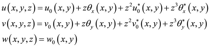
The displacements at any point inside the plate using nodal unknowns can be assumed in the following form ([21]) as
 (1)
(1)
The in-plane displacements ![]() and
and ![]() have been expanded in powers of the thickness coordinate z to enable a parabolic variation of transverse shear stress through the thickness, moreover no shear correction factor is required. By doing this, some extra unknowns at each node have been incurred in the computation. All the extra terms in the expansion polynomials
have been expanded in powers of the thickness coordinate z to enable a parabolic variation of transverse shear stress through the thickness, moreover no shear correction factor is required. By doing this, some extra unknowns at each node have been incurred in the computation. All the extra terms in the expansion polynomials  are either displacements or rotations that enrich the in-plane variation of displacements u and v in a nonlinear manner and capture the warping of the laminate cross section in the case of a thick plate. But this small extra computa-
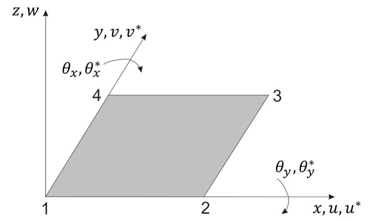
Figure 1. Element configuration, local node number and nodal degrees of freedom of the element.
tional cost is fully compensated by vastly improved stress results. Two transverse shear strains  and
and  are also taken as nodal unknowns in this formulation. These two terms are not present in the plate kinematics but hidden in the equations related to
 [as shown later in Equation (3)]. No attempt has been made to enforce zero transverse shear at the top and bottom surface of the plate as that does not produce any better stress results [15].
2.2. Displacement Formulation
In total the element has eleven degrees of freedom at each node. So in total 44 unknown coefficients are attached to each element that needs to be manipulated (Figure 1). The polynomials taken for this element are given explicitly below:

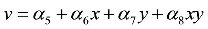

 (2)
(2)
The other two nodal unknowns  for shear deformable plate theory can be defined as given below
 (3)
(3)
Arranging all nodal unknowns in a vector array , we get
 (4)
(4)
or, (5)
(5)
where,  is a 44 × 44 square matrix;
  and
and  are vectors of dimension 44 × 1.
The linear strain-displacement relationships (from Equation (1)) can then be written as
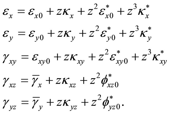 (6)
(6)
The complete strain matrix could be formed by taking the suitable derivatives of the displacements in spatial coordinates (i.e. ) and forming the matrix populated by both
 ![]() - or
- or ![]() -coordinates and coefficients
-coordinates and coefficients![]() .
.
2.3. Strain Displacement Matrix
The strain equations (Equation (6)) can be grouped as given below
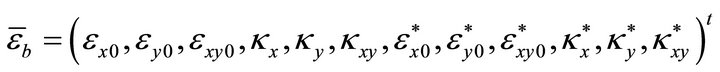
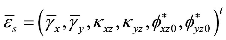 (7)
(7)
Herein  and
and  are the membrane, bending and shear strains respectively. The complete set of strains can be obtained by simply assembling all the components in correct order
 (8)
(8)
The corresponding stress resultants are given below
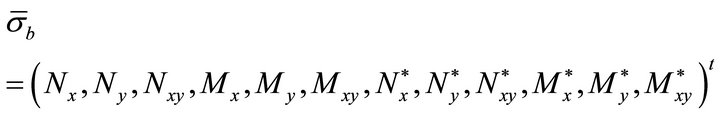
 (9)
(9)
where  and
and  are the membrane, bending and shear stress resultants. Separating
  from the coordinate terms, the strain matrix
  (Equation (8)) can be written as
 (10)
(10)
Using Equation [4], it can be written as
 (11)
(11)
where  is the well known strain-displacement matrix for the element.
2.4. Equilibrium Equations
For equilibrium, the total potential energy must be stationary and using the stress-resultants (Equation (9)) and mid-surface strains (Equation (8)), the principle of virtual work can be written as
 (12)
(12)
Herein U is the strain energy of the laminate and  is the work done by the external forces. These are evaluated by the following expression
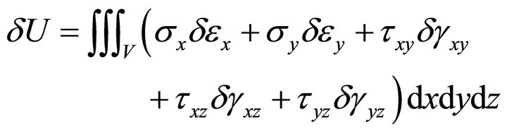 (13)
(13)
with the usual meaning of the terms within the integration. Integrating through the plate thickness and substituting in terms of mid-surface strains and introducing the stress resultants, the above Equation (13) can be written down in the following form
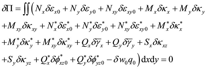 (14)
(14)
Equation (14) represents the equilibrium equation of the medium, where  represents the external transverse load on the structure.
2.5. Element Stiffness Matrix
To compute the element stiffness matrix, we need to define the elastic rigidity matrix of the composite plate. The elastic rigidity of the plate can be directly constructed from the strain expressions (Equation (6)). For completeness of the treatment, the final expressions are included below
 (15)
(15)
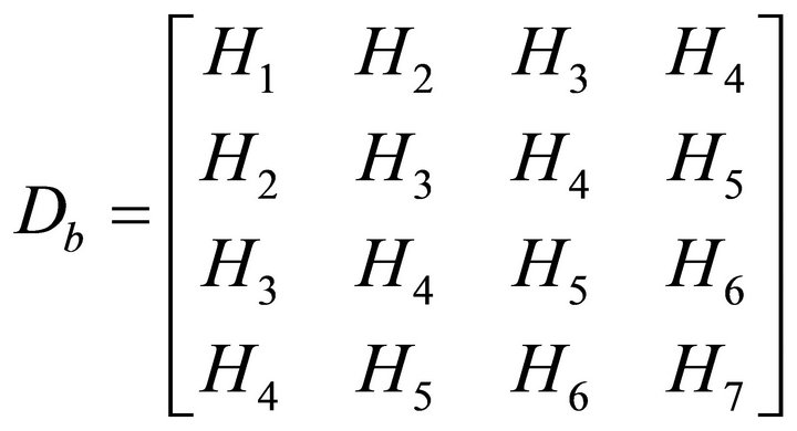
where
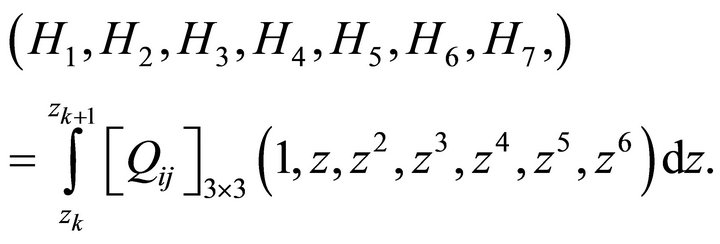 (16)
(16)
Herein  is the in-plane and bending elastic rigidity matrix including all higher order terms and
is the 3 × 3 reduced in-plane stiffness matrix of the ply. Similarly the entire shear elastic rigidity matrix can be expressed as
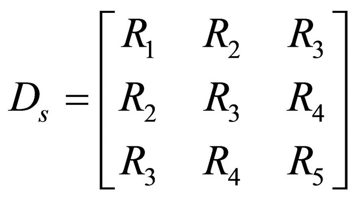 (17)
(17)
where
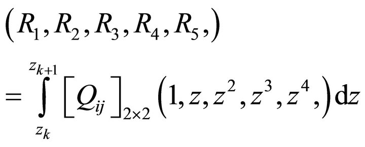 (18)
(18)
and  is the 2 × 2 reduced transverse shear stiffness of the ply. So the final form of the elastic rigidity matrix of the plate is
 (19)
(19)
So, finally the stiffness matrix can be formed by standard finite element procedure as shown below
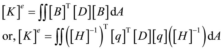 (20)
(20)
Herein [D] is the elastic rigidity matrix of the given plate continuum suitably developed as shown in the Equation (19).
2.6. Interlaminar Shear Stresses
It is well known that the transverse shear stresses computed from the constitutive relationships become discontinuous through the layers due to the difference in ply properties. So alternatively the interlaminar shear stresses can be computed from the equilibrium equations ensuring continuity through the thickness as given below
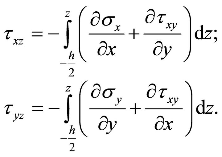 (21)
(21)
3. Numerical Examples
Several numerical examples are provided in this section to establish the effectiveness of the element developed here. The examples include isotropic as well as composite materials. The loading considered in these examples is concentrated, uniformly distributed or sinusoidal varying loading applied on the plated structure. All the examples containing composite laminates are made of polymer fiber composites (uni-directional). The sandwich material is made of stiff composite face skins and soft core material. The orthotropic properties of all these materials are given below:
Material Properties:
Mat1: Isotropic Material: E = 10.92GPa, ν = 0.3.
Mat2: Fibre-Reinforced Single Layer Material for Laminate E11/E22 = 25, E22 = E33 = 7 GPa; G12 = G13 = 0.5*E22‚ G23 = 0.2*E22; ν12 = ν13 = ν23 = 0.25.
Mat3: Core Material E11 = E22 = 0.28 GPa, E22 = E33 = 3.5 GPa; G13 = G23 = 0.42 GPa‚ G12 = 0.112 GPa; ν12 = ν13 = ν23 = 0.25.
3.1. Isotropic Simply Supported Plate under Uniformly Distributed Load
The first example considered in this study is a simply supported isotropic plate subjected to uniformly distributed loading. Results from the present study (Table 1) have been provided for various mesh divisions and compared with the analytical solution given in ref. [4,9]. The study shows a good convergence rate for the presented element from lower bound to the exact value (analytical thin plate solution). All the mesh divisions indicated in Table 1 are for the full plate. Results are provided for the non-dimensional vertical displacements at the centre of the plate and the central moment. In the table,  is the bending rigidity of the plate,
  and
and  is the loading and length dimension in global
 ![]() -direction respectively.
-direction respectively.
Considering the convergence study above for moments and displacements, the 12 × 12 mesh for the full plate has been considered sufficient for engineering accuracy. So, all the examples given below will be studied with the 12 × 12 mesh division without any further mention.
3.2. A Square Plate with Three Edges Simply Supported and Free at the Fourth Edge
A simply supported plate with three simply supported
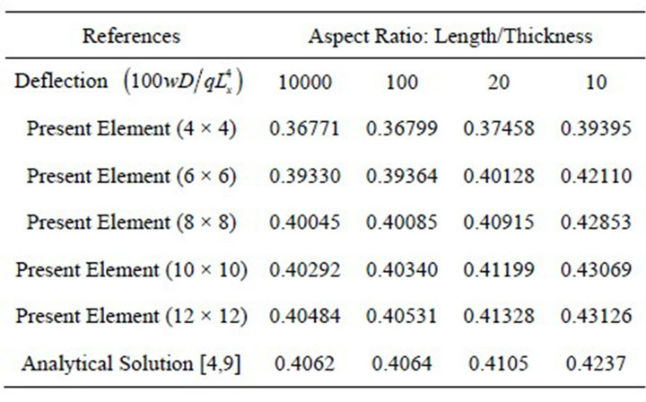
Table 1. Non-dimensional deflection at the plate center for isotropic plate under uniformly distributed load
edges and a free edge has been analyzed using the present element for various aspect ratios. The plate has been subjected to uniformly distributed loading on its top surface. All the results given here have been obtained with the 12 × 12 mesh division and the calculated numerical data in the form of normalized displacements and moments are presented in Table 2. The results have been compared with other published data [4,11] and found to be in reasonably good agreement. The deflections and moments for the range of aspect ratios between 5 and 10,000 show that the element is actually lock-free and in the case of a thin plate (aspect ratio of 10,000), the results converge close to the analytical solution for the thin plate. The normalized displacements and moments are as follows:
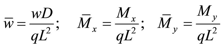
where 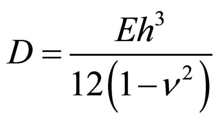 and
and  and
and ![]() are the Young’s modulus and Poisson’s ratio of the isotropic plate;
are the Young’s modulus and Poisson’s ratio of the isotropic plate; ![]() and h are the side length and total thickness of the square plate.
and h are the side length and total thickness of the square plate.
It can also be seen from Table 2 that the developed element has successfully handled the thick plate cases (aspect ratio of 5) and the corresponding deformation and
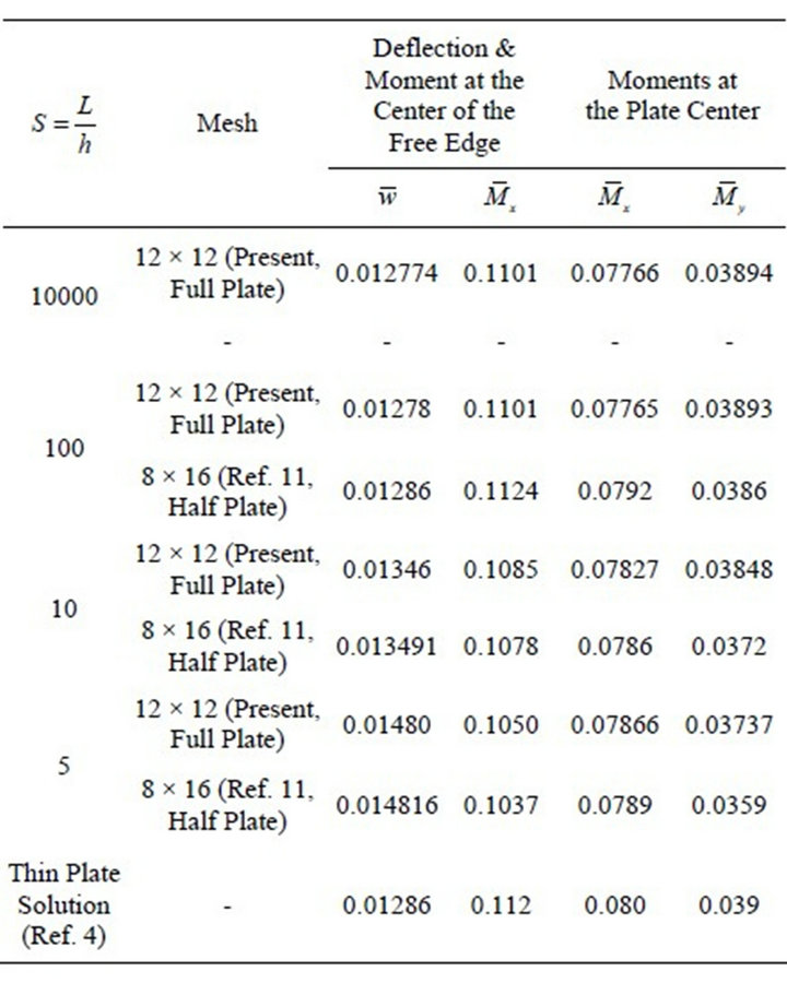
Table 2. Normalized displacement and moments at the edge and plate center of a square plate under uniform load with three edges simply supported and a free edge.
moments match with the other published finite element solution [11].
3.3. A Cantilever Plate under Concentrated Tip Loading at the Free End
To prove the applicability of the proposed element under different structural configurations and loading/boundary conditions, a cantilever plate under point load at the free end has been considered next. Figure 2 provides the configuration of the cantilever beam with the loading arrangement. The cantilever plate is made of isotropic material with constant thickness. The dimensionless material properties are taken to be  for Young’s modulus and
  for Poisson’s ratio. The dimension of the plate is: Length
 ; and width
 . The free end of the cantilever beam is subjected to a concentrated load
  (
( are kept dimensionless as per [14]). The vertical displacement at the free end of the cantilever is evaluated and compared with other available results ([14]) and given in Table 3.
With the limited available results, the present element provides engineering accuracy for the cantilever plate in satisfactory accordance with that of published results.
3.4. A Three-Layer Symmetric Cross-Ply [00/900/00] Square Composite Plate
A simply supported three-layer symmetric cross-ply [00/900/00] square composite plate  has been analyzed under sinusoidal surface loading. For this case an analytical solution has been given earlier by Pagano [7]. All plies are considered to be of equal thickness.
The loading distribution is

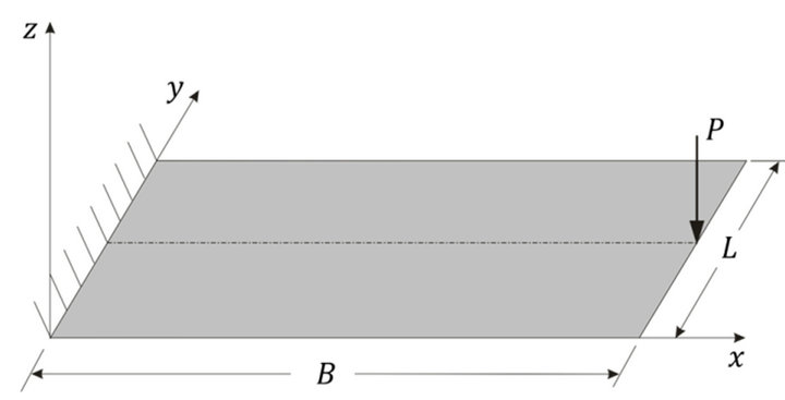
Figure 2. Structural configuration with point loading at the free end of a cantileverplate.
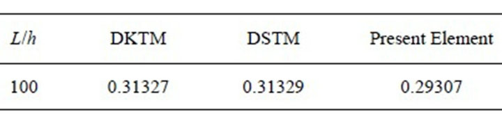
Table 3. Vertical displacement w for a cantilever plate under concentrated loadingat the free end.
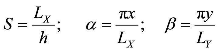
where ![]() and
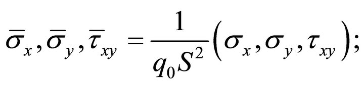
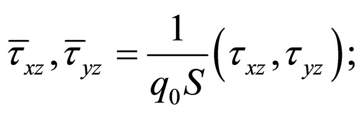
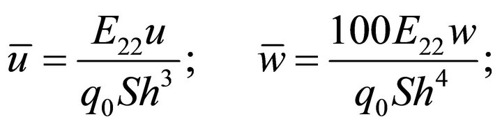
and  have been defined below. The results from elasticity solution, classical laminated plate theory (CLPT) and the present approach are presented for various aspect ratios. Displacements and stresses are normalized in the following way:
The respective results are given in tabular form Table 4.
This example demonstrates clearly that the proposed element is handling both thick and thin composite plates for layer-wise stresses with reasonable numerical accuracy and in good accordance with the elasticity solution of Pagano [7]. The difference of the interlaminar shear stress computation by the present element to that of the elasticity solution is similar to that of Engblom et al. [12]. This clearly demonstrates that the new element really can capture the bending response of multi-layered composite plates with various ply directions through the thickness.
3.5. A Four Layer Symmetric Cross-Ply [00/900/900/00] Square Composite Plate
This is a similar example of a cross-ply simply supported square composite plate as studied in the previous case. This example has been studied by Pandya & Kant [15] using the finite element method and an elasticity solution has been provided by Pagano et al. [8]. The results for stresses at various aspect ratios are provided in Table 5 in comparison to other sources. The stresses are normalized exactly in the same way as in the previous example.
3.6. A Simply Supported Three-Layer [00/Core/00] Sandwich Plate
The refined element as presented here works also well for sandwich plates, where the stiffness of the core is much lower than that of the top and bottom skin. A three-layer square simply supported sandwich plate as proposed by Pagano [7] has been analyzed to highlight the capability of the proposed element. Two aspect ratios for the plate have been considered for this case. The sandwich plate consists of three layers, top and bottom skin (Mat2) and in between a soft core (Sandwich core material, Mat3). The skin layers have the thickness of  (h is the total thickness). The corresponding results are provided in Table 6.
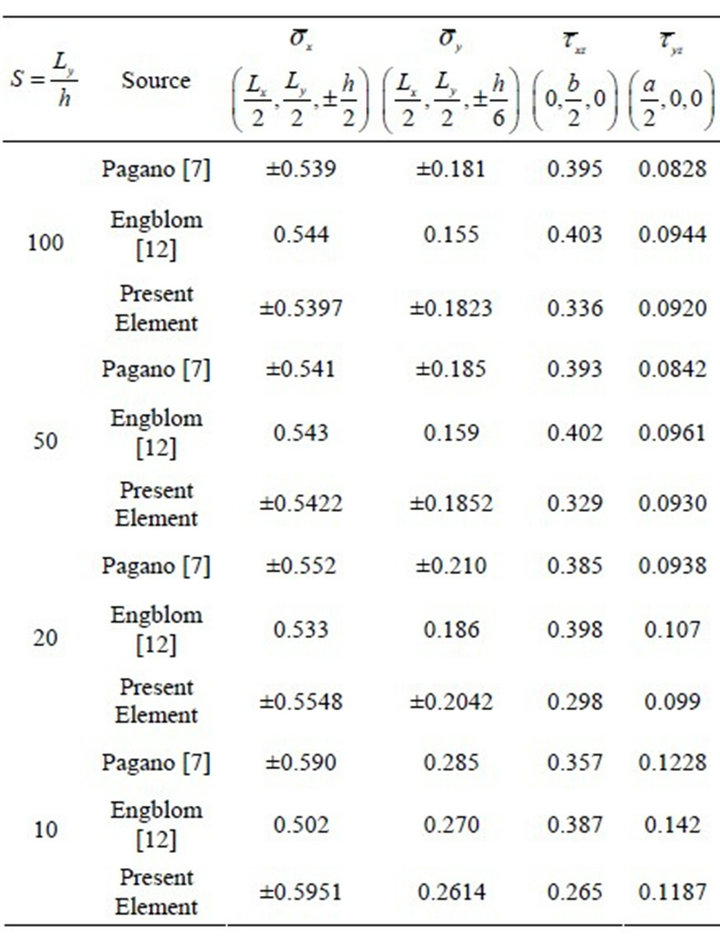
Table 4. Normalized stresses for the three-layer symmetric [00/900/00] plate.
As in the cases of the last two examples, the element has handled the thick and thin plate situations well, but also it has handled well the extreme difference between the stiffnesses of the top and bottom skins with a high elastic modulus and the very soft middle core. This is a clear indication that the polynomials considered for the unknown displacements and rotations are sufficient for a good convergence in all sorts of cases in isotropic plates, polymer composites and sandwich plates.
4. Conclusion and Discussion
A four node rectangular element with eleven degrees of freedom per node has been presented in this study. The element has been formulated based on a higher order refined shear plate theory with an expansion of the inplane displacements up to cubic order and constant transverse deformation w. A Fortran code has been developed to implement the above mentioned element to study the performance. This non-linear variation of inplane deformation provides more accurate results in thick composite plates. Numerical experiments show that the element is lock-free in nature. Results for extremely thin plates (aspect ratio of 10,000) to moderately thick plates of aspect ratio of 5 have been presented with consistently good accuracy compared to that of other available published results. The element also exhibits a good conver-
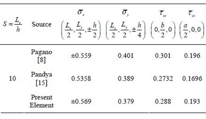
Table 5. Normalized stresses for the four layer symmetric [00/900/900/00] plate.
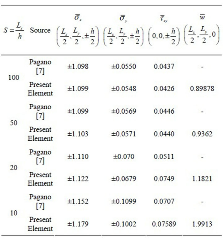
Table 6. Deflection and maximum stresses of three-layer [00/core/00] sandwich plate.
gence rate for both displacements and bending moments at the plate center and the free edges. Several examples of isotropic plates and composite/sandwich plates have been presented. For all the cases, the results are consistent and show excellent agreement with those of elasticity/analytical thin plate solutions and other published finite element results. The element can easily be coded up and can be integrated to research/commercial software.
REFERENCES
- E. Reissner, “The Effect of Transverse Shear Deformation on the Bending of Elastic Plates,” Journal of Applied Mechanics, Transaction of American Society of Mechanical Engineers, Vol. 12, No. 2, 1945, pp. A66-A77.
- R. D. Mindlin, “Influence of Rotary Inertia and Shear on Flexural Motions of Isotropic Elastic Plates,” Journal of Applied Mechanics, Transaction of American Society of Mechanical Engineers, Vol. 18, No. 1, 1951, pp. 31-38.
- O. C. Zienkiewicz and R. L. Taylor, “The Finite Element Method,” McGraw-Hill, New York, 1989.
- S. P. Timoshenko and S. Winowsky-Krieger, “Theory of Plates and Shells,” 2nd Edition, McGraw-Hill, New York, 1959.
- J. M. Whitney, “The Effect of Transverse Shear Deformation on the Bending of Laminated Plates,” Journal of Composite Materials, Vol. 3, No. 3, 1969, pp. 534-547. doi:10.1177/002199836900300316
- N. J. Pagano, “Exact Solutions for Composite Laminates in Cylindrical Bending,” Journal of Composite Materials, Vol. 3, No. 3, 1969, pp. 398-411. doi:10.1177/002199836900300304
- N. J. Pagano, “Exact Solutions for Rectangular Bidirectional Composites and Sandwich Plates,” Journal of Composite Materials, Vol. 4, No. 1, 1970, pp. 20-34.
- N. J. Pagano and S. J. Hatfield, “Elastic Behavior of Multilayered Bidirectional Composites,” AIAA Journal, Vol. 10, No. 7, 1972, pp. 931-933. doi:10.2514/3.50249
- A. L. Dobyns, “Analysis of Simply Supported Orthotropic Plates Subjected to Static and Dynamic Loads,” AIAA Journal, Vol. 19, No. 5, 1981, pp. 642-650. doi:10.2514/3.50984
- D. G. Ashwell, A. B. Sabir and T. M. Roberts, “Further Studies in the Application of Curved Finite Elements to Circular Arches,” International Journal of Mechanical Sciences, Vol. 13, No. 6, 1971, pp. 507-517. doi:10.1016/0020-7403(71)90038-5
- A. H. Sheikh and P. Dey, “A New Triangular Element for the Analysis of Thick and Thin Plates,” Communications in Numerical Methods in Engineering, Vol. 17, No. 9, 2001, pp. 667-673. doi:10.1002/cnm.440
- J. J. Engblom and O. O. Ochoa, “Finite Element Formulation Including Interlaminar Stress Calculations,” Computers & Structures, Vol. 23, No. 2, 1986, pp. 241-249. doi:10.1016/0045-7949(86)90216-6
- M. Guenfoud, “Presentation de l’Element DSTM pour le Calcul Lineaire des Coques d’Epaisseur Quelconque,” Ann l’ITBTP, Vol. 515, 1993, pp. 25-52.
- L. Belounar and M. Guenfoud, “A New Rectangular Finite Element Based on the Strain Approach for Plate Bending,” Thin-Walled Structures, Vol. 43, No. 1, 2005, pp. 47-63. doi:10.1016/j.tws.2004.08.003
- B. N. Pandya and T. Kant, “A Consistent Refined Theory for Flexure of a Symmetric Laminate,” Mechanics Research Communications, Vol. 14, No. 2, 1987, pp. 107- 113. doi:10.1016/0093-6413(87)90026-7
- S. Goswami, “A C0 Plate Bending Element with Refined Shear Deformation Theory for Composite Structures,” Composite Structures, Vol. 72, No. 3, 2006, pp. 375-382. doi:10.1016/j.compstruct.2005.01.007
- G. R. Bhashyam and R. H. Gallagher, “An Approach to the Inclusion of the Transverse Shear Deformation in the Finite Element Plate Bending analysis,” Computers and Structures, Vol. 19, No. 1-2, 1984, pp. 35-40. doi:10.1016/0045-7949(84)90200-1
- S. Goswami, “A Finite Element Investigation on the Effects of Cross-Sectional Warping on Flexural Response of Laminated Composites and Sandwiches using Higher Order Shear Deformation Theory,” Journal of Reinforced Plastics and Composites, Vol. 24, No. 15, 2005, pp. 1587-1604. doi:10.1177/0731684405050398
- C. W. Pryor Jr. and R. M. Barker, “A Finite Element Analysis Including Transverse Shear Effects for Applications to Laminated Plates,” AIAA Journal, Vol. 9, No. 5, 1971, pp. 912-917. doi:10.2514/3.6295
- J. N. Reddy, “A Penalty Plate Bending Element for the Analysis of Laminated Anisotropic Composite Plates,” International Journal for Numerical Methods in Engineering, Vol. 15, No. 8, 1980, pp. 1187-1206. doi:10.1002/nme.1620150807
- N. D. Phan and J. N. Reddy, “Analysis of Laminated Composite Plates using a Higher Order Shear Deformation Theory,” International Journal for Numerical Methods in Engineering, Vol. 21, No. 12, 1985, pp. 2201- 2219. doi:10.1002/nme.1620211207
- R. K. Kapania and S. Raciti, “Recent Advances in Analysis of Laminated Beams and Plates,” AIAA Journal, Vol. 27, No. 7, 1989, pp. 923-946. doi:10.2514/3.10202
- J. N. Reddy and D. H. Robbins, “Theories and Computational Models for Composite Laminates,” Applied Mechanics Review, Vol. 47, No. 6, 1994, pp. 147-165. doi:10.1115/1.3111076
- A. K. Noor, S. Burton and C. W. Bert, “Computational Models for Sandwich Panels and Shells,” Applied Mechanics Review, Vol. 49, No. 3, 1996, pp. 155-199. doi:10.1115/1.3101923
- X. Y. Zhang and C. H. Yang, “Recent Developments in Finite Element Analysis for Laminated Composite Plates,” Composite Structures, Vol. 88, No. 1, 2009, pp. 147-157. doi:10.1016/j.compstruct.2008.02.014
NOTES
*Corresponding author.