International Journal of Astronomy and Astrophysics
Vol.3 No.1(2013), Article ID:29456,23 pages DOI:10.4236/ijaa.2013.31007
Possible Signs of Life on the Planet Venus
Space Research Institute of the RAS, Moscow, Russia
Email: ksanf@rssi.ru
Received November 30, 2012; revised December 31, 2012; accepted January 10, 2013
Keywords: Extraterrestrial Life; Venus; Physical Conditions
ABSTRACT
It is possible, the question on the existence of extraterrestrial life will be answered not as a result of its search for in other worlds removed by distances of dozens of parsecs but on the surface of Venus, i.e., of the nearest planet of the Solar system. The search for “habitable zones” in extrasolar planetary systems is based on the postulate on “normal” physical conditions, i.e., the pressure, temperature, and maybe atmospheric composition similar to those on Earth. But could not such an approach be a kind of “terrestrial chauvinism”? Considering the conditions on Venus as a possible analogue of physical conditions on low-orbiting exoplanets of the “super-Earths” type, a new analysis of Venusian surface panoramas’ details has been made. These images were produced by the VENERA landers in 1975 and 1982. A few relatively large objects were found with size ranging from a decimeter to half meter and with unusual morphology. The objects were observed in some images, but were absent in the other or altered their shape. The article presents the obtained results and analyzes the evidence of reality of these objects.
1. Introduction
During the 17 years after 1995 almost 1000 extrasolar planets around other stars were discovered. The position of the hypothetical habitable zone of extrasolar planetary systems is compared, as a rule, with its position in the Solar system. The search for “habitable zones” in extrasolar planetary systems is based on the premise of “normal” physical conditions in a “habitable zone”, i.e. pressure, temperature, and possibly atmospheric composition similar to those on the Earth. Of course, the known Earth’s life forms require exactly the “normal” physical conditions. However, is the possibility that life forms can exist under very different conditions common to many exoplanets, can be fully excluded? Approximately one third of exoplanets orbit their stars at very low orbits which lead to relatively high temperatures of their surfaces. In those cases when it is possible to investigate the atmosphere of these “hot jupiters” they really turn out to be very hot and their composition—oxygenless [1-3]. For methodological reasons, direct analogs of the Earthlike planets have not been found yet. It is estimated that the temperature on the surface of an extrasolar planet such as “super-Earth”, located close to a star of relatively low luminosity, may lie in the range of 550 - 900 K. When considering the habitable zone of a large group of bodies with a moderately hot atmosphere, one should not exclude completely the possibility of the existence of life at relatively high temperatures, despite the lack of the experimental data of this kind, and that at the first glance it seems impossible. “There is a possibility that we find life based on a quite different chemical composition (without carbon and/or water)”—wrote B. W. Jones in Life in the Solar System and Beyond (2004). Detailed studies of objects situated at a distance of tens of parsecs are impossible at the present level of research instruments. However, there is the planet Venus more or less available, with its dense, hot (735 K) oxygenless СО2-atmosphere and high 9.2 MPa pressure at the surface [4-7 and others]. In this way Venus could be the natural laboratory for the studies of this type.
The only existing data of actual close-in observations of Venus’ surface are the results of a series of missions of the Soviet VENERA landers which took place in 1975 (VENERA-9 and -10 landers) and 1982 (VENERA-13 and -14), working in the atmosphere and on the surface of Venus [8-16 and others]. One of the images returned by the VENERA-14 lander is shown in Figure 1. No other similar experiments have been carried out since then, primarily because of their extreme engineering
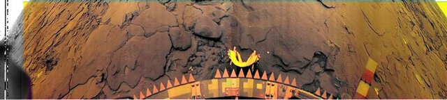
Figure 1. Panoramic view of the Venus’ surface at the landing site of the VENERA-14 lander.
complexity. A total number of returned panoramas and their fragments reach 41 [10,12].
After receiving the first panoramas of the planet’s surface in 1975 the question of the existence of life forms on Venus scarcely arose. Curiously, that in the first panoramic view transmitted by VENERA-9 one could see a motionless object of a strange symmetrical shape reminiscent of a sitting bird measuring about 30 cm. The object attracted attention and was commented on as a deceptive form of stones [11,17].
37 and 30 years elapsed since the VENERA-9, -10 and VENERA-13, -14 missions, respectively. For last years, the author repeatedly returned to the obtained images of the Venus’ surface in order to reveal unusual objects which had been observed in the real conditions of Venus. The impetus to the audit and new attempts to analyze the results of the previous missions to Venus were the vast stream of new research results of exoplanets with moderate masses. Amid such exoplanets, celestial bodies with the physical conditions similar to the Venusian should be met.
The new analysis of the Venus’ panoramas was based on the search of unusual elements in two ways. Since the efficiency of the landers maintained for a long time they produced a large number of primary panoramas or their fragments. The published images were created by combining the most successful panoramas which had been produced in black-and-white and color-divided versions. Due to the low noise level of the first serials (1, 2) of VENERA-13 images, for a black-and-white panorama it was enough to use two snaps, which permitted elimination from them of the so called “telemetry insets”—the information from other devices of the lander. But besides these panoramas, there are other primary images which cover much time of the lander’s work. Thus, one can try to detect: (a) any differences in successive images (appearance or disappearance of details of the image or change of their shape), and understand what these changes are related to (e.g., wind), or whether they are related to hypothetical habitability of the planet. Another sign (b) of the wanted object is their morphological peculiarities which distinguish them from the ordinary surface details like stones. It could be their symmetry or regular shape which is intrinsic to living species but not peculiar to stones. This paper is devoted to the research results of the images returned by the landers VENERA-9, -13, -14.
Of importance is a sophisticated image processing, as seen in Figure 2. After it the details not noticed before are getting visible. As a byproduct Figure 3 shows the crater, probably of a volcanic origin, for the first time photographed directly on the surface by the VENERA-13 camera. It has a diameter of about 1400 m and it seems that it is surrounded by the old traces of broad lava

Figure 2. Above same as Figure 1 after 2012 processing. Below—the VENERA-14 landing site, as it would have seen by a human eye (the geometric distortions eliminated). The white arc feature at the center is the detached lid of the scanner window.

Figure 3. An old distant crater with a diameter of about 1 km, is probably of volcanic origin. The yellow color is inherent to the sky of Venus.
flows. One can even assume that the crater is filled with a fog, a stuff of unknown nature. Similar volcanic craters are observed only by radar facilities orbiting Venus.
With the improvement of methods of processing, the images become more vivid. Contours of previously inconspicuous details became clearer. By this way interesting objects have been found, which are shown in next sections. The object even in the foreground of the VENERA-13 panorama didn’t attract any attention before the new image processing was done.
It must be emphasized that in the course of processing of initial images any retouching, additions making or correction of images was completely ruled out. The use of any version of the PHOTOSHOP nonlinear program was entirely ruled out, too. Where necessary, the contrast and brightness were adjusted. For noises suppression in the 6th serial of the VENERA-13, standard operations of the WINDOWS system has been applied. A more concrete explanation of the image processing methods and procedures is given in the text and in Appendix.
2. Brief Information about the Experiment
Express-results of the missions VENERA-13, -14 were published in the special issues of the “Kosmicheskiye Issledovaniya” magazine, V. XXI, No. 2 - 3, 1983. Results of the missions VENERA-9, -10 were described in detail in [8]. More information on the properties and the duration of the experiment, its technical characteristics and volume of the data obtained is provided in the Appendix.
Each VENERA lander was provided by two TV cameras. The images of Venus’ surface were obtained using photometric scanning cameras of optical-mechanical type with a single-channel receiver—a photomultiplier with a multialkali photocathode [12]. The VENERA-9 and -10 (V9/10) cameras were black and white (spectral interval 390 - 750 nm), cameras of VENERA-13 and -14 (V13/14) were fitted with glass filter discs. Spectral intervals were 410 - 750 nm (no filter), 390 - 510 (blue), 490 - 610 (green) and 590 - 720 nm (red filter). The blue images are useless, because the blue rays are almost completely absorbed by the Venus’ atmosphere. The cameras’ optics entrance was located at a height of 0.82 m (V9/10) and 0.90 m (V13/14) above the surface. The cameras were placed on both opposite sides of each lander. As distinct from traditional television systems, the images produced by each of the cameras were panoramic (a horizontal field of about 180˚), with lines oriented vertically, having a resolution of 115 pixels (21 arc min each), 517 lines (V9/10), and 211 pixels (11 arc min each), 1000 lines (V13/14). The images were transmitted by a radio transmitter’s omni-directional antenna to the satellite in the elliptical orbit. The satellite relayed the data from the lander to the Earth’ receiving stations in real time. The scanning cameras axes were inclined at an angle of 50˚ to the vertical which allowed to discern after processing few millimeter-sized features of the surface in close proximity to the lander, and about 10 m at the mathematical horizon (at a distance of 3.3 km on a flat surface). The inclination of the camera’s axis distorts images. If one converts the image so that the horizon line was straight, a rectangular image would transform into an area bounded by two arcs (Figure 2).
The results given in the next section start with the VENERA-13 lander data which operated unbelievable long. It landed in the equatorial zone of the planet at 7.5˚S, 303.5˚E, Eastward of the Phoebe area. Physical conditions were the following: temperature 735 K, pressure 8.87 MPa; the altitude of the landing site was 1.9 km above the level of 6050 km (mean Venus radius). Gas analyzers showed that the atmosphere almost entirely consisted of CO2 (96.5%) and N2 (3.5%), the atmospheric density was 59.5 kg/m3. Local time was about 10 o’clock in the morning, the solar zenith distance 37˚. The illuminance estimation of the scene was up to 3500 lux [18]. Image transmission started in few minutes after landing.
The images that are used for the search of any objects or phenomena associated with their appearance, disappearance or change of their forms, had been received mostly by the camera 1 of the VENERA-13, in series called 1, 2 and 6. Denotations are as V-13-1-6 BW that means VENERA-13, camera 1, series 6, black and white image (or R for red and G for green). The next section presents analysis of the images’ parts of the Venus’ surface based mainly on a sequence of nine panoramas of the camera 1 which were obtained sequentially during 2 hours 06 min. In addition, the data of the camera 2 (series 3, 4, 5) were used. The total duration of the camera V-13-2 operation was 60 min. Many fragments shown in the paper are taken from VENERA-9 and VENERA-14 panoramas. Analysis of details of surface images allowed identifying some objects that satisfy the criteria set forth above. For convenience, they are called by nicknames, which, however, are only conditional and names are non-binding.
3. Fixed Objects “Hesperos” and “Owl”
3.1. “Hesperos”
On synthesized color panoramas processed and published immediately upon completion of the experiment [12], several objects were distinguished according to their regular shape and lighter yellowish shade (Figure 4). In this case, some of them were located sufficiently close
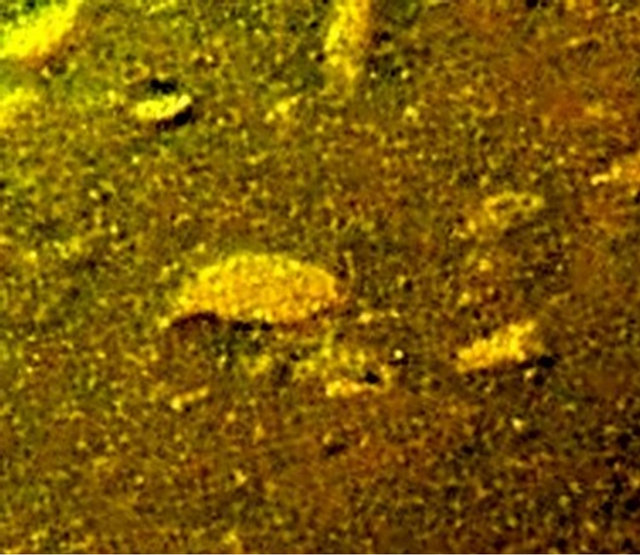
Figure 4. Original image with a prolate object “hesperos”, 20 - 22 cm in size (the high-quality fragment of the VENERA-13 color panorama without additional processing).
to the lander, which allows considering them in detail.
The contours of these objects (for the view from above) remind of felt leaves. However, some similar objects resembled not leaves but spindles. They were conditionally called “hesperos”, which corresponds to the ancient Greek name “Εσπεροσ” of the planet Venus. A large hesperos is shown in Figure 4. It is located at a distance of 1.6 m from the input optical window of the camera and is seen at an angle of 35˚ to the horizon. Assuming the hesperos surface to be horizontal, its perspective reduction attains 57%. Under the hesperos the shadow is seen which indicates that the hesperos either has volume or is elevated above the surface.
The sizes of hesperos vary but basically, are close to 20 cm, as is the case of Figure 4. At first glance, the hesperos in Figure 4 may be considered to be a stone. However, the facts given below indicate its unusual properties. Hesperos have attracted attention not only by their regular shape. Quite similar objects were discovered both on opposite sides of the lander (camera 2, VENERA-13) and on the panoramas of the other landers. At the VENERA-13 opposite side the hesperos had the same shape but its size is close to 12 cm. During the time of the expedition both objects were scanned multiple times; however, no displacements were found. The hesperos presented in Figure 4 is clearly seen on all panoramas of the color-divided and black and white V-13-1-1 and V-13-1-2 series. The additional increase of the image sharpness was reached by means of application of the group image-processing approach. The method of correlative stacking, which was used in the course of processing electron images of Mercury [19] was employed. The processing was made for color-divided images V-13-1-1 (BW, R, G) and V-13-1-2 (BW, R) of series 1 and 2 of VENERA-13, which were obtained for the first 87 min of the lander action. It turned out to be rather productive and made it possible to see image details overlooked previously. The processing results for the entire group of images of the indicated series, which were obtained with camera 1, are presented in Figure 5. The right-hand parts of the objects exhibit a small dark head-shaped segment. On the left, an elongated tail is seen. It is possible to distinguish the transverse band in the middle of the hesperos and to see fine details in its right-hand head shaped part. In Figure 5, frame 2, the right-hand side of the object is terminated by projecting prolate forms that resemble whiskers intrinsic to numerous living species of the Earth. Their exterior shape is sufficiently convincing. Nevertheless, one, of course, cannot exclude that the observed “whiskers” are formed occasionally by fragments of light rocks on the adjacent surface.
The more detailed Figure 6 presents a complicated
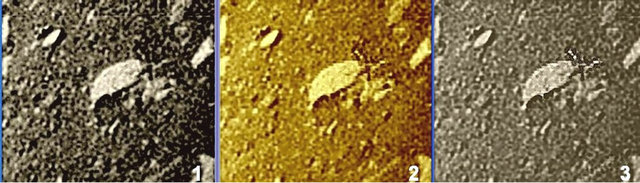
Figure 5. Three versions of the combined processing of six images on panoramas of the V-13-1-1 and V-13-1-2 series. An unknown complicated light structure (probably not connected to the object) is located before the hesperos.
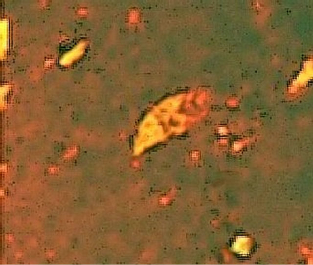
Figure 6. Processing with the preferable use of red colordivided images. The structure and the regularity of lines and spots hardly intrinsic to stones are seen.
structure of the hesperos. The image is slightly dispersed; however, fine details are distinguishable. Here, a transverse band is clearly seen that separates the left-hand yellowish part of the hesperos from the darker right-hand one, having a dark head-shaped segment. The structure of this object is marked by regularity of its lines and spots, which is not a case for stones. In Figure 6, the irregularities of the ground are smoothed.
The incomplete identity of original images arises by virtue of noticeable variations in the illuminance of the planet’s surface, which attains 30% - 40% during the time of the expedition. Most likely, the oft repeated opinion on the uniform brightness of the Venusian sky is not valid at all. It is not excluded that under the action of meteorological conditions, the spectral (color) composition of the incident radiation also varies slightly. This is indicated by certain differences in the color-divided panoramas.
3.1.1. The Hesperos Analog in the Region of the VENERA-9 Landing
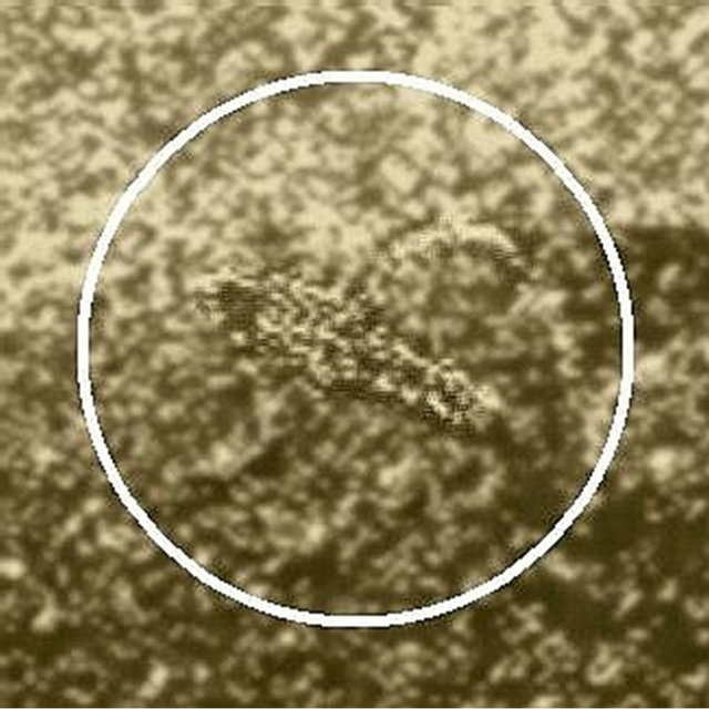
As mentioned above these interesting objects of a characteristic shape were found in the panoramas of VENERA-13. This region is a flat country; however, a very similar hesperos is presented in the panoramas of VENERA-9. This lander reached Venus surface by seven years earlier in the southern foothills of the Theia mountain region, at a distance of 4400 km to the north from the future VENERA-13 landing site. In [20] two large objects, found on the first 174˚-panorama of VENERA-9 were considered. In the same mission, the second (incomplete) panorama enveloped an angle of 120˚. The quality of the second panorama is significantly worse than that of the first one. The hesperos is most clearly seen on the fragment obtained as a result of the combined processing of the both VENERA-9 panoramas (Figure 7).
There, the hesperos is marked by a white circle. The length of the object is 25 cm. This is one of the largest hesperos among those considered. Despite the fact that the resolution of VENERA-9 cameras is two times lower than that of VENERA-13, here one can easily distinguish the elongated form of its regular shape with a dark head-shaped part and a light tail part. This occurs insofar as the hesperos is located at a distance of 1.04 m, i.e., almost two times closer than in Figure 1. It has a slightly larger size and is seen at an angle of 51˚ to the horizon. The prolate tail segment of the object is the same as in Figure 5. As opposed to the region of the VENERA-13 landing, the hesperos in Figure 7 is located among stone lumps whose size attains 1 m. Thus, under the assumption that hesperos actually represent Venusian fauna, they inhabit both flat country and mountain regions among stones.
3.1.2. Processing Fragments of Multiple Panoramas
Compared to other discovered objects, hesperos is the
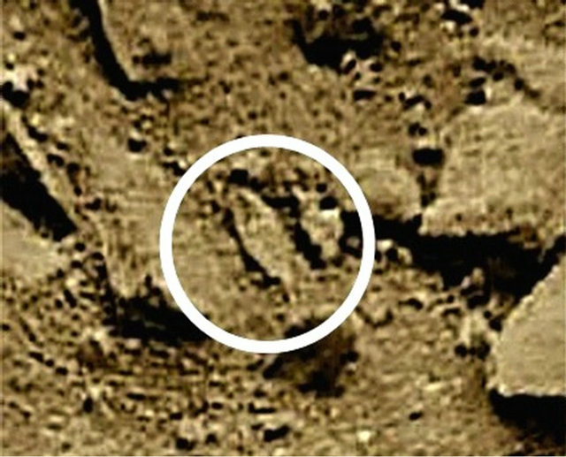
Figure 7. Fragment of new processing of panoramas of VENERA-9. In the circle, there is an object of the hesperos type, which is located close to the camera. The object length is 25 cm; the distance of the landing site to the hesperos shown in Figure 1 is 4400 km. To be compared with Figures 5 and 6.
most widely propagated form. Two objects of the same shape as in Figure 4 are also seen on the periphery of the panoramas for both cameras of VENERA-13. These objects are located on opposite sides of the lander. The object in the panorama taken by camera 2 is positioned at a greater distance (2 m) from the camera and is visible at an angle of about 28˚ to the horizon. It is observed in all successive panoramas recorded by camera 2. The left hand frame of Figure 8 is a fragment of the color panorama obtained and processed in 1982-1984 [14]. The arrow shows a supposed hesperos. For a new combined processing the same method of correlative stacking [19] was used again. It is an example of the processing efficacy and how the complex processing was applied. To this end, fragments of 13 panorama fragments, namely, V-13-2, series 3, 4, and 5 (BW, R, G) were selected. The results are shown in Figure 8. Frames 1, 2 and 3 correspond to the fragments jointly processed by the [19] method, each based on the 3 - 4 successful images (obtained at different times). Significant improvement of the image has been obtained. Frame 4 presents the result of the whole combined processing of the images 1 - 3. It is the best achieved result demonstrating how effective the processing method is. The dark left-hand edge part of the hesperos is head-shaped, whereas the prolate right-hand part is terminated by the narrowing tail segment. The shadow contour under the object is sharp but is located in a different manner at 1 - 4 frames. The reason for this, probably, is the non uniform directivity of the illuminance and the presence of the lander’s shadow. One may conclude that, in addition to shadows repeating the object contours, and the regular contours of the object in themselves, one is able to identify only its black head-shaped part, the thickened body, and the tail segment that seems a bit darker.
3.1.3. Possible Hesperos in the VENERA-14 Panorama
The panoramas of the landing site of the VENERA-14 lander present the geological province of another type compared to those of VENERA-9 and VENERA-13. These panoramas have been studied for long time, and now one may state that similar interesting objects are also observed here. However the thickened body in Figure 9 is not exactly of characteristic shape of hesperos.
An object was found in the panorama of camera 2 of the VENERA-14 lander (Figure 9). It is seen clearly and is located sufficiently close (only 1.3 m) to the optical input window of the camera and is seen at an angle of 61˚ to the horizon. Its size is 10 cm. The object is in a protected place resembling an alcove or a broad hole. Comparison with Figures 7 and 8 indicate the unquestionable similarity and identical size of these forms. However, comparison with Figures 4 and 5 show the difference in the colors and shades of the objects, and the object’s

Figure 8. Hesperos on the side of camera 2: a fragment of the first color panorama (arrow) [14] and results of processing of 13 fragments of panoramas of VENERA-13, which were obtained in time intervals from 13 to 49 min. The hesperos is 12 - 13 cm in size; 1, 2, and 3 are the results of processing of 3 to 4 different original fragments, 4 is the result of the combined processing of the whole sequence.
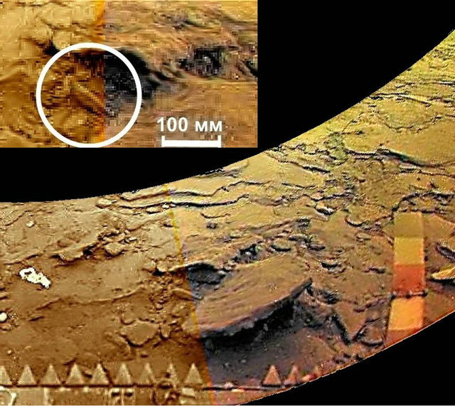
Figure 9. An object on the side of camera 2 of the VENERA-14 panorama is marked by white circle. To be compared with Figure 8. The size of the hesperos is about 10 cm. The distance to it is 1.3 m. Its head-shaped part (on the left) is connected by a certain manner to the adjoining detail, like a semi-ring.
body being more bulky. The left-hand head-shaped part of the object seems has a complicated structure. This part is surrounded by a regular detail, like a semi-ring whose plane is inclined to the left. The nature of the semi-ring, of course, is unknown. But one may recall that on the frames with the “scorpion”, a similar semi-ring closely adjoining the object is clearly seen [21].
The objects found on the panorama of VENERA-14 are not exhausted by similar features exhibited in Figure 9.
The regions investigated by the VENERA landers are located at great distances from each other. The landing site of VENERA-14 is at a distance of 900 km to the East from that of VENERA-13, and almost at 4500 km to the South from that of VENERA-9. Nevertheless, objects, similar in their shape, size, and structure were observed in all three regions. Of course, it is impossible to reliably announce that all of them relate to the same species. If the hesperos in Figures 4, 5 and 7 seem to be plane structures, then in Figures 8 and 9, they are more bulky.
3.2. “Owl”
Nearly 7 years earlier, less sophisticated spacecrafts, VENERA-9 and -10, landed on the surface of Venus (October 22 and 25, 1975). In all these landers optical-mechanical scanning cameras were installed, one on each side of the lander. Unfortunately, on both VENERA-9 and -10 only one camera opened, the lid of the second one was not released. The second camera worked fine, but the window remained closed. The VENERA-9 and -10 cameras [10,11] were designed for only blackand-white TV-images. The cameras design, the images, methods of their processing and interpretation of planetologic results were detailed in a special edition “The first panoramas of Venusian surface” [8].
A curious feature of the experiments was the use of powerful lights for the field illumination, consisting of 100-Watt halogen lamps and reflectors [11]. The experiment was performed for the first time, and there was no certainty that the surface will be in good lighting conditions despite the daytime. The precaution was not justified. The VENERA-10 first panorama coverage was 174˚. The image was coded in a 6-bit (64 levels) system and transmitted through an omni-directional antenna of the lander’s transmitter to the orbiter (a satellite in the 48- hour orbit) and relayed in real time to Earth through its narrow-beam antenna. The noise level in the images received on Earth was low. However because of the limited resolution, the panoramas, in their original form and even after a complicated processing, left much to be desired. Nevertheless the images (especially the rich in detail image from VENERA-9) permit additional processing by more modern software and methods [20]. Besides it, a flexible, though very time consuming software “Astronomic Image Processor”, designed by Dr. V.Kakhiani (not yet published) was applied. After the new processing the image became much more clear (as illustrated by Figure 10), and quite comparable to the panoramas of VENERA-13 and -14. The landing points of the landers were located in the equatorial part of the northern hemisphere of Venus, at the longitude of the Theia and Rhea mountains, to the South from them, 31˚42'N, 290˚50'E (VENERA-9) and 16˚02'N, 291˚00'E (VENERA-10). Although the area is relatively flat, VENERA-9 went down on a hillside and inclined by 9˚48' to the horizon [22]. In the additionally processed panorama (Figure 10) probably a distant hill slope is visible to the left. The distance between the landing sites of VENERA-9 and VENERA-10 was 1600 km.
The first scanning of VENERA-9 panorama contains many interesting details. “Strange stone” is the first of them.
Long Story of the “Strange Stone”, 1975-2012
In the far right of Figure 10, in the foreground, there is an object of a complex structure, which immediately attracted the attention of researchers. In papers [16,23] the object is called a “strange stone with a rod part protruding and a lumpy surface”. Presenting a somewhat blurred image of the fragment, their authors wrote ([16], p. 113): The shape of the “strange” stone which is located to the right of the gamma densitometer is difficult to determine. It is seen in a strong perspective. A distinctive feature of this stone is the overall roundness of the convex side facing the camera, which is combined with the surface color darker than that of the plate-rocks, of a spotted (probably pit-and-mount) nature. The transverse dimensions of the spots (mounts?) are 3 - 5 cm. At the top of the stone there are two clear round protrusions, with a diameter of about 5 cm and a height of about 3 cm. To the left of the stone described there is a bright elongated direct protrusion, which is identified as protruding from the stone rod-like feature of a lighter material and about 15 cm in length and about 5 cm thick at its base. On the right the dark spotted surface is joined by a crooked
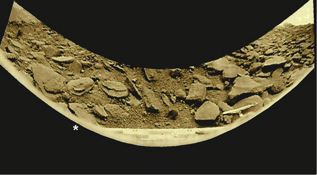
Figure 10. The panorama transmitted by the VENERA-9 lander on October 22, 1975 from the planet surface. The new processing of the same initial image was applied. When processing the telemetry insets were replaced, where possible, by fragments taken from another panorama.
alignment to a lighter surface, its character is not clear because of its proximity to the edge of the panorama. In general, this mottled stone makes an impression of a weak non-homogeneous formation (at least at the surface) consisting of lightly cemented breccias”. The authors presented two images of the “strange stone”, corresponding to the direct and reverse camera scans. That part of the panorama with the “strange stone” was used for the cover of the “First panoramas of the surface of Venus” edition [8]. My attention was attracted by the “strange stone” immediately, on October 22, 1975, when the VENERA-9 panorama was obtained. Unfortunately, later all my attempts to interest my colleagues in the strange object were in vain. The notion of impossibility of life in high temperature conditions for colleagues at the Space Research Institute of the Academy of Sciences of the USSR and the administration of the Institute was an insuperable barrier to any discussion. Yet, when a year before the publication of the work cited above [23], my book “Planets discovered anew” [17] was published, it did give the image of the “object of an unusual shape”. The following comment to the picture was given: “The object details are symmetrical relative to its longitudinal axis. Lack of clarity hides its contours, but… with some imagination you can see a fantastic inhabitant of Venus”. Accordingly, the text on pages 50 - 51 read: “… Did VENERA-9 land near a living inhabitant of the planet? … We most likely see a stone of an unusual shape, like a volcanic bomb… With a tail”. Only the sarcasm of the final phrase showed that the opponents had not quite convinced the author in the physical impossibility of life on Venus. However, in the monograph “The planet Venus” [7] the hypothesis of life on Venus was not mentioned, since the issue of energy sources essential for life in the oxygenless atmosphere was (and still is) unclear. Below the “strange stone” is conventionally referred to as the “owl”.
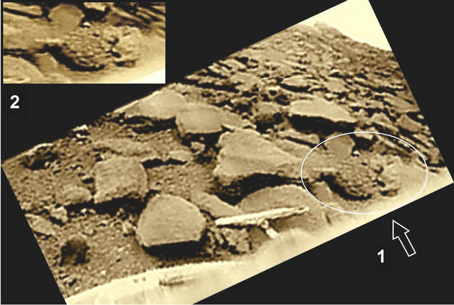
In 2003-2006 the image processing was improved and the quality of the image with the “strange stone” was noticeably improved too [20]. Detailing of the panorama gets better, but still insufficient for definitive conclusions. Only in 2012 a final processing was developed. The processed fragment of the right side of Figure 10 is presented in Figure 11(a), where the “owl” object is marked with a white oval and arrow 1. It is seen from above, at an angle of about 55˚ to the horizon. The “owl” object is distinguished by its strange longitudinal symmetry, and its appearance can hardly be interpreted as a “strange stone” or “volcanic bomb with a tail”. The position of the “spotty surface” details reveals a certain radiality extending from the right side, from the “head”. The tail continues strictly the longitudinal symmetry of the “owl”. The “head” itself is of a lighter hue and has a complex symmetrical structure with large shapely dark spots, also
 (a)
(a)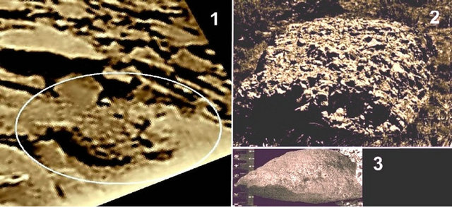 (b)
(b)
Figure 11. (a) Complex symmetrical shape and other characteristics of the “owl” object (arrow 1) distinguish it against the planet’s rocky surface at the VENERA-9 landing site. The object is about half a meter in size. The “owl” object can be a real inhabitant of Venus. Its regularly organized morphology with a pronounced longitudinal symmetry seems to make this assumption quite plausible. Above (2)—the geometric distortion of the image is corrected. (b) (1)—Repeated image from Figure 11(a) the size of “owl” is about a half meter. (2)—A piece of volcanic breccia of 1-meter in size which, according to [24], “is similar to the owl body”. (3)—A piece of lunar basalt that according to [24] “is resembling the owl’s tail”.
symmetrical, and perhaps with some bulge at the top, as mentioned in [23]. In general, the structure of the massive “head” part is rather difficult to understand. It is possible that some small stones, accidentally coinciding in light hues, are arranged so that they seem to be features of the “head”.
But the form of “owl’s” main part is so regular that it would be difficult to consider it just as a “strange” stone. The configuration of the “owl” image in Figure 11(a), 1) is left intentionally the same as in the original panorama that allows comparing it with the images presented in [8]. The entire structure of the “owl” is lengthened slightly when a corrected geometry is applied which makes the “owl” more “slender” (Figure 11(a), 2). The straight light “tail” mentioned above really has a length of 13 - 16 cm and it casts a shadow, too. The length of the whole “owl” is 35 cm, or 48 - 51 cm including the “tail”. The shadow cast under its body fully repeats the contours of the object, which is elevated above the surface. Its height is not less than 25 cm. Thus, the size of the “owl” is quite large, which allowed obtaining its sufficiently detailed picture even with the limited resolution of the scanning camera and, of course, due to proximity of the object. In the case of the “scorpion” (VENERA-13) the panorama was noisier than the VENERA-9 panorama (Figure 10). But in the considered part of the image it was almost not affected by any noise. The image actually corresponds to an object that was just in front of the camera during shooting. It seems appropriate to ask: if what we see in Figure 11 is not an inhabitant of Venus, then what is it? Apparently, the evidently complex and highly organized morphology of the “owl” makes search for other hypotheses rather difficult. The false impression may be created only by random combinations of light and dark surface features (rocks, shadows). It should be mentioned that during the time of the mission neither “hesperos” nor “owl” showed any displacements.
The hypotheses that the “owl” is an inhabitant of Venus got an active consideration in literature, in the magazine “Solar system research”, 2012, V.46, #5. The authors of papers [24,25] of the six comments follow a critical position in regard to the papers [20,21]. Four other authors [26-29]—support the validity of the experimental findings, and the leading authority in biophysics [26] confirms that the possibility of life on Venus does not violate principles of biophysics.
The author of the critique paper [24] considers the geological features at the VENERA-9 landing site. He believes that “the strange stone” or “owl”, is “volcanic breccia: a rock composed of rounded angular fragments cemented by volcanic material, lava or tuffaceous material”. He illustrates it by a photo and concludes: “In pictures one sees the agglutinate pile of clastic breccias and their roughly rounded shape in large fragments and outcrops, which makes them similar to the body of “owl” in the panorama VENERA-9”. Figures 11(b)-2 and 11(b)-3 are repeated from the paper [24] and should be compared with the “owl” image, the surface of which is not inherent to stones. Next the critique paper [24] reads: “Thus, in our view, the object ‘strange stone’, also known as ‘owl’, may well be a random combination of rounded fragments of volcanic breccia (the body), adjacent at the right to a pile of small pebbles (as a head) and left leaning sphenoid fragments of basalt (as a tail)”.
One may conclude that Figures 11(b)-2 and 11(b)-1 have few in common. The object in Figure 11(b)-3 looks more like a shark. It is possible that much more similar in their shapes stones could be found. However, most important is the fact that the limited original material contained in panoramas neither permit consolidating categorically that the object belongs for sure to the Venusian fauna, nor that it is a stone. Yes, regularity in the “owl” structure seems permit proposing such suggestion. Nevertheless, in all cases a character of the interpretation as a hypothesis is underlined. The same is valid for the remark about the dark trail (next section). The main goal about the trail discussion was what kind of stuff could be liquid on Venus.
4. Terramorphic Objects with Mobility or Its Traces: “Scorpion” and “Anemos”, “Colobok”, “Teddy Bear”
4.1. “Scorpion”
During the mission the lander got hotter and problems in its functioning appeared. In the V-13-1-6 BW image (series 6) a noticeable noise is present, most probably of electromagnetic origin. It manifested as numerous white dots and their clusters (Figure 12). The noise properties are so that it could be partly suppressed. However the image V-13-1-6 BW yields to images of series 1 and 2. An interesting object, nick-named “scorpion” appeared around the 90th minute, namely on the image V-13-1-6 BW, together with the adjacent “semi-ring” at its right side.
Before the appearance of the “scorpion” image the lander has been working for more than 1 hour 27 minutes (the start time of the image V-13-1-6 BW scanning). Thus, the first assumption was that this regular structure was a product of destruction of some part of the lander. But the lander VENERA-13 continued to work after it for a full hour. The systems’ operability showed that the crash had not happened yet; otherwise the lander would have failed due to catastrophic overheating at once.
Analysis of the available technical documentation showed that all the external operations (e.g., throwing away of the lids, drilling of the ground, etc.) had been completed for a short period of time, not exceeding 20 - 30 minutes, and that nothing else had separated from the lander. The assumption of a separated part contradicts also the fact that in the subsequent images the object “scorpion” is missing.
As shown below, one of possible explanation is that the appearance and subsequent disappearance of the

Figure 12. The V-13-1-6 BW panorama was scanned during the period 87 to 100th minute after landing. A noise as numerous white dots appeared probably due to the growing temperature of the lander’s electronics. The object “scorpion” is marked by the white circle.
“scorpion” could be connected with the soil destruction and its throwing aside when landing, rather than with direct influence of the wind. The work [30] provides the information that the wind speed in this period was low (0.4 m/s) and decreasing only. In Figure 12 the object is placed to the left of the center. It has a more or less regular structure (Figure 13(a)). The length of the object is about 17 cm.
Apparently, the complex and regular shape of the “scorpion” cannot be a result of random combinations of light, halftone and dark points. The image of the “scorpion” consists of m = 940 pixels, while the number of pixels in the panorama covering 177˚ is . The probability p of the formation of such images is
  (when only combinations,
  are taken into account), where the number of combinations is
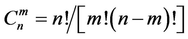 that is a monstrous value, and the probability
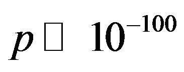 . In other words, the probability of a random occurrence of the object’s image is excluded. In addition, there is a physical indication of its reality. One can see a shadow under the object (Figure 13(a)). Formation of shadow due to accidental combination of points is, of course, impossible. The shadows show that it is a relief object and is situated above the surface.
Despite of it, there is a critical article [25] that considers the “scorpion” to be an artifact. The author of [25] considers different types of digital encoding and modulation of the radio signal transmitted from VENERA-13 to the Earth. Differences of content of images the paper [25] explains as transmission defects. The text in the page 413 [25] reads: “One of the anomalous objects… in the form of “scorpion” is indicated by the arrow… However, this feature is completely absent in the PCM transmission”. This conclusion is a strange methodic mistake: the paper [25] compares two different panoramas as one and the same, despite they were taken with an interval of about 87 minutes! How could they be identical?
The Figure 13(b), reproduces two images presented in [25]. If the images 1(a), 1(b) would processed normally, as in [21], the appearing fragments (Figures 13(b), (2a) and (2b)) are getting the well known fragments of the panoramas that in [21] are designated as V-13-1-1 BW and V-13-1-6 BW, shown in Figures 13(b), (3a), (3b). They were obtained at the time intervals 0 - 13 min and 87 - 100 min, respectively. In the criticized paper [21] all timings of getting of each panorama were given. Besides, differences between files V-13-1-1 BW and V-13-1-6 BW are easy to be followed by the content of their first and second telemetry insets.
Thus, the criticism [25] is incorrect. Differences of content of pictures are related to events on the surface of the planet and not to the properties of the radio link.
 (a)
(a)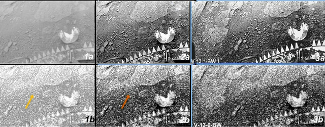 (b)
(b)
Figure 13. (a) The object “scorpion” appeared in the image V-13-1-6 BW at about the 90th minute after landing. (b) (1)—A pair of fragments presented in the article [25] as one and the same picture; (2)—The same images after processing by the author’ system; (3)—Identification of the images as panoramas fragments V-13-1-1 BW (top) and V-13-1-6 BW (bottom) obtained during the time intervals 0 - 13 min and 87 - 100 min, respectively.
Returning to “scorpion”. In its proximity there is an object in a form of semi-ring, which is a strange feature, called “Anemos”, changing its shape in the subsequent images (Figure 14). Looking for the Earth’ analogues one may remember anemones—tentacles of sea polyps living in shallow water. The positions and orientation of the features are shown by arrows. The time intervals are 13 min between 1 - 2 frames, 39 min between 2 - 3 and 26 min between 3 and 4 - 5 frames. The pair of semirings in action is seen in Frame 3, Figure 14. It touches the scorpion’s body. Before and after the frame 3, a short double “anemos” instead of the semi-ring is present. The thickness of anemos’ body is about 0.5 - 1 cm, length of the semi-ring is about 10 cm. Their orientation changes for 90˚ between frames 1, 2 and 4, 5. Changing of the length and position of the anemos is not a result, say, of the wind. Due to the low resolution details of images are not seen.
Object “scorpion” has a complex structure that may remind some large terrestrial spiders or insects. In the preceding images collected before the 87th minute the object is absent (Figure 15). Unfortunately, the last preceeding image V-13-1-2 R, referring to the 66th - 79th min, is ruined completely in this part by the noise and is not presented here. The object is absent in the subsequent images V-13-1-2 R, G, too (beginning at the 100th and 113th min). The probable reason may be that if the object was moving away during time when the scanning camera
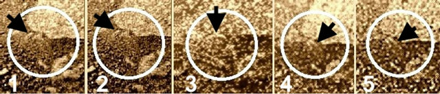
Figure 14. “Anemos” changing their position, orientation and length to “semi-ring” shape and back, during 126 min.
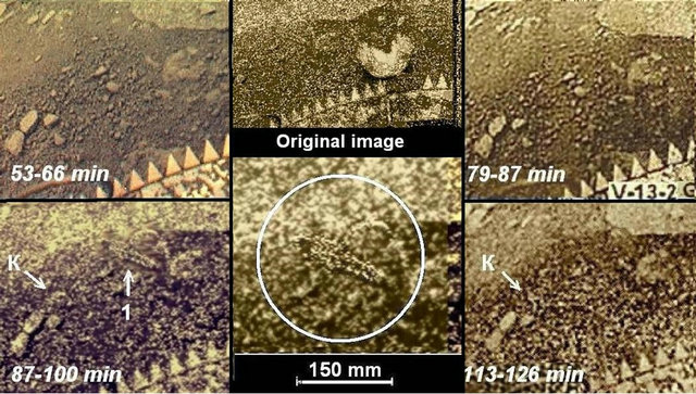
Figure 15. The object “scorpion” (1) appeared in the panorama that was being snapped from the 87th to 100th min. On the images obtained before the 87th min and after the 113th min the object is absent. In the images of the 87th - 100th and 113th - 126th min, at the left, in the group of stones, a new pattern K appeared which is changing its position. It is absent in the images of the 53th - 66th and 79th - 87th min. In the central part of the figure both original image and the result of the image processing are shown. The size of the “scorpion” is about 17 cm.
returned to it, the image resolution at a large distance deteriorated. At a distance of 3 - 4 m the object became indistinguishable from stones. The object would have to move off at such a distance in 26 minutes—at that time the scanner returned once again to the same area on the panorama. For such displacement a minimal speed of the “scorpion” should be 2 mm/s.
As noted above, due to tilt, the camera image distortions occur (see Figure 2). But near the “scorpion” camera’s distortions are small and no corrections required. There is another possible cause of distortion—the movement of an object during scanning. The panorama’s V-13-1-6 BW shooting was spent 780 s, and the part of the image with a “scorpion” took 32 s. The displacement of the object’ image could have caused, for example, an apparent elongation or reduction of the image.
Note again that in the image processing no retouching or adding details was applied. Processing of panorama V-13-1-6 BW was to reduce the white dots noise by successive application of the minimum levels of “blurring” and “sharpening” made by the standard MICROSOFT OFFICE programs in WINDOWS system and selecting the necessary contrast and brightness. The view of object “scorpion” in Figure 15 fully corresponds to its view in the V-13-1-6 BW panorama.
In the left hand side of Figure 15, there is visible a group of three stones, sized 40 - 50 mm. In the frames 87 - 100 and 113 - 126 min there appeared one more, the fourth object, of round shape (arrow K), measuring about 50 mm. On the previous frame (53 - 66 min and 79 - 87 min) it is absent. In frames 87 - 100 and 113 - 126 min the object position is different, and its shape changed. Its small size does not allow distinguishing its details.
What Might Have Happened around VENERA-13 on the 90th Minute?
In an attempt to find an explanation for the emergence of “scorpion” in the late panorama the following facts were compared.
1. Object “black flap” (side of the camera V-13-2) disappeared after the first image.
2. At all subsequent panoramas of camera V-13-2 any moving objects were not detected except for the “black flap” (see Section 5 below). Camera’s 2 work ceased officially at 59 min [12], actually it worked longer.
3. During this time, in the panoramas of the camera V-13-1 moving objects were not detected, too. The two subsequent panoramas partly are noisy, and only a part of them is suitable.
4. “Scorpion” appeared only about 90 min, and in the image taken 26 minutes after, it was absent.
5. Comparison of the type of surface on both sides of the lander shows a relatively consolidated soil at the side of the camera V-13-2, and a loose, fragmented soil at the camera V-13-1 side.
6. Soil, ejected on the landing buffer is seen mostly by the camera V-13-1 side. The opposite side of the buffer remained relatively clean. This fact was noted already in first publications.
Between possible hypotheses explaining the late appearance of “scorpion” might be namely one-sided ejection of the soil that buried the “scorpion” by a thin layer. When landing, the vertical velocity of the lander found by the dynamic method, was 7.6 m/s [9], and the side velocity was within the error of the method. One may expect that the side velocity was about the same as the wind speed (0.3 - 0.5 m/s, see below). The landing blow was 50 Venusan g. The unit crashed the soil to a depth of about 5 cm [9] and ejected it aside in lateral movement. That is why both the powdered buffer and surface are presented mainly at the camera’s V-13-1 side. By a lucky circumstance, the entire series of V-13-1 is of low noise, and the V-13-6 G panorama amenable to reduce noise. They all are presented in detailed 9-bit TIFF format (plus 1 bit housekeeping). The place of occurrence of “scorpion” was studied in all available panoramas. The results are shown in Figure 16. On the first image (7 min), on the ejected soil is a shallow oblong groove visible, with its length about 100 mm. In the second image (20 min) sides of the grooves seem are raised, and the length increased to about 150 mm. The orientation of the grooves

Figure 16. Successive images of the soil area, ejected in the direction of the wind velocity of the lander when landing. Minutes of scanning the area are indicated.
is the same as that of the “scorpion”. In the picture of 59 min a part of the regular structure of the “scorpion” appeared. On the 93rd minute the “scorpion”, apparently, recovered completely from the soil that filled it. The thickness of soil that buried it probably not exceeded a 1 - 2 cm. Thus, the rescue operation of the object took about 1.5 hours. One can assume that this indicates its limited physical abilities. In the picture 119th min, it was no longer visible.
As an alternative cause of displacement of the object the possible role of the wind was considered. At high atmospheric density at the surface of Venus (ρ = 60 kg/m3 at the VENERA-13 site), the dynamic effect of the wind is equivalent to 8-fold the wind speed at the Earth’s surface.
The wind speed was measured on Venus in many experiments, for example, by the Doppler residual of the radio signals [31] that for VENERA-13 was estimated to be within 0.3 m/s. Wind speed in the landing sites of VENERA-13, -14 was also measured by observing movement of dust on the landing buffer [13,30] and by acoustic noise of wind in the microphone of the GROZA instrument [30,32]. Due to the low position of the microphone (14 cm above the surface), the wind speed 0.43 - 0.48 m/s, found in the experiment can be attributed to the “scorpion” position. With the wind speed 0.48 m/s and the atmospheric density 60 kg/m3, the dynamic pressure ρv2/2 of wind on the “scorpion” cross-sectional area gives about 0.08 N, which is hardly enough to move the object. Nevertheless, the movement of “scorpion” due to the wind is one of quite possible hypotheses, too.
The coincidence of time of scanning the panorama V-13-1-6 BW with the advent of object “scorpion” (which, apparently, had not yet been able to move fast) was a big success of the experiment. Either the success was a position of the shooting scene, where the existing resolution of the camera permits to trace the development of all these events, as well as the disappearance of the object in the final panorama.
4.2. “Colobok”
A trace of a possible movement of an object in VENERA-9 panorama is shown in Figure 17. A dark continuous trace stretches from the torus of VENERA-9 landing buffer (point marked by an asterisk in Figure 10

Figure 17. The dark trace stretches from the point of the landing buffer marked by an arrow. It is supposed that the trace was left by a wounded object. The trace is formed by some liquid substance of unknown nature (there can be no liquid water on Venus). The object having about 18 cm in size managed to travel a 26 - 30 cm distance during no more than 6 min. In the bottom, there is a fragment of a photoplan that enables to measure scene details at equal scale and compare their location.
and by an arrow in Figure 17) to the left over the surface of a stone. A black trace continues coming off the stone, broadens and ends near a round light-colored object with a pointed black left part which may be similar to several other objects of the Venus’s fauna. It is nicknamed “colobok”. The trace after the “colobok” is very dark. There are no similar traces on the panoramas made by any VENERA probes. And judging by the trace’s density it is formed by some liquid substance of unknown nature which cannot be water. 647 K and 22 MPa are critical data for water. The temperature 735K and pressure 9.2 MPa at the surface are beyond critic point that is 578 K for Venus. Thus, there could not be any liquid water there. This substance should be represented by some unknown high temperature water solution, or some other unknown substance. However, how did the trace appear?
The following assumption can be made about the origin of the trace that starts near the landing buffer system of the lander: if the “colobok” is a part of Venus’s fauna, here, it could be damaged by the buffer whilst VENERA landing. And “colobok” left a dark trace that oozed out of its tissues when it started creeping away. If it were a terrestrial animal such trace would be called bloody. Location of “colobok” in the panorama corresponds to the 6th minute of scanning, and the distance that was covered by the object before the 6th minute was 26 - 30 cm. The scanning camera was switched on soon after landing. Thus, basing on the time of scanning (6 min) and location of the “colobok” one can determine that its speed was 6 cm/min or 1 mm/s i.e., similar to the value defined in the previous section.
The second part of the critical paper [24] concerns the trail as “just a gaping crack in the stone with a flat surface, within which this dark band is observed”. But, as seen in Figure 17, the track goes down from the rock, continues and expands on the ground.
In the photoplan (the bottom of Figure 17) one can see the “colobok” with corrected geometry and equal size scale where the “injured object” is situated among large stones. One cannot conclude whether it was moving next, because the second VENERA-9 panorama did not reach the “colobok”. The dark trace itself also proves that the considered objects can move at a speed of at least 6 cm/min (1 mm/s) in danger even provided that they are injured. It should be reminded that the mentioned above object “scorpion” disappeared from the panorama between the 93rd and 119th minute of operation of the probe. To realize this it had to move at least at a speed of 2 mm/s. Probably, a slowness is typical for Venus’s fauna and is connected with its finite energy reserves as was the case with the “scorpion” which spent 1.5 h for its own recovery, as supposed above. In contrary, no movements of the “owl” and “hesperos” objects were observed. It should be noted that representatives of terrestrial fauna possess high power available in comparison with Venus’s fauna. Very favorable conditions on Earth contribute to it, particularly a plenty of flora suited for nutrition and the oxidizing atmosphere.
4.3. “Teddy-Bear”
Comparing consequently obtained images as momentary pictures one can see that some objects substantially transfer or leave the observed area. Some objects have left obvious transference traces. Such studies afford to draw a conclusion about their dynamics and determine the supposed transfer velocities available to them.
Apparently, terramorphism of several types of Venus’s fauna is a great surprise relating to the complex problems of searching of life in the Universe. If the objects are in significantly different physical conditions and nevertheless, have similar forms, then some yet unknown laws of nature should be the basis of such phenomenon. In this regard, an object nicknamed “teddy-bear” is most interesting (Figure 18). It was found in 2012 in an additionally processed panorama of VENERA-9 that had been obtained in 1975. The “teddy-bear” is situated in the foreground of the image, in the centre of the panorama, in the near vicinity of the camera. Its contour is more ‘soft’ and a kind of downy in contrast with sharp edges of the surrounding stones. The teddy-bear is located close to the camera, at a distance of 0.93 m from its optical input and is observed from the top at an angle of 62˚ to the horizon. It bases itself upon the “limbs” with a gap

Figure 18. The fragment of an additionally processed VENERA-9 panorama. In the foreground one can see a small object, a “teddy-bear” that is distinguished from the stones’ sharp edges by soft contours. To the left, one can see long furrows that extend from a flat stone and end under the “teddy-bear”. Apparently, these traces are indicative of its movement.
seen between them. And as far as one can judge, the limbs remind animals’ paws, and the teddy-bear looks like a small animal which is as big, for example, as a little dog. If one assumes the teddy-bear stands vertically which is confirmed by a similar position of shadows from stones, the objects’ height should be 30 - 34 cm and length about 16 - 20 cm.
Important details are observed to the left from the teddy-bear in Figure 18. Here, one can see 4 or 5 long furrows 65 - 70 cm in length that begin near a flat stone, pass around a huge boulder situated higher and flow around a small object about 5 cm in size. The furrows tail after the teddy-bear ending near its “paws”. There are no such traces in front of it or to the right. Apparently, the furrows left after it have been produced by its movement, which affords to estimate its extremely important property—its velocity of travel and may be even its maximum speed of movement. Its velocity can be calculated if one assumes that the teddy-bear was trying to run away and started to move at the moment when the probe landed close to it. (The lower part of the image adjoins the probe’s landing buffer system). The time of full panorama scanning was 30 min, and it took about 16 min from the beginning of scanning to the time when the teddy-bear appeared in view. Thus, the maximum speed the teddy-bear could have in the extreme conditions leaving, say, the 64-cm-long furrows was 64/16 = 4 cm/min, or less than 1 mm/s. It was stated above that the speed of movement characteristic for other objects of the hypothetical Venus’s fauna can be very low, in terrestrial terms.
Is it a justified conclusion? It is not improbable at all that the teddy-bear’s speed of movement was significantly higher. The object could move faster and then stop at the place seen in the picture. This assumption can be justified in the following way. In the course of the mission VENERA-9 two panoramas were obtained, however, the second one was incomplete. It covered only 124˚, had poor quality than the first one and couldn’t be processed well. The teddy-bear is not clearly seen in this panorama, but comparing it with the one in the first panorama one can conclude that location of the teddy-bear did not change much and the shift does not exceed several centimeters in the past 25 min after the first scanning. Thus, it is not excluded that under critical conditions it was moving faster and then stopped before the 16th minute of scanning.
Can other reasons of formation of the furrows be found, for example, relocation of the teddy-bear due to the action of a wind? As mentioned above, in [30] the value of wind velocity was presented that had been measured at the VENERA-13 landing site, and it was equal to . Measurements of the other VENERA probes gave the same figures [7]. A “moderate” terrestrial wind blowing at a speed of 4 m/s can be an equivalent. Same as above, the possibility of movement of the teddy-bear driven by the wind is determined by its velocity pressure
 . Provided that gas density
  and lateral area S = 0.05 m2, wind pressure will be the following: F = 0.26 N. Assuming the mass of a body 1 kg and a friction coefficient 0.2, this pressure is not sufficient to move the object and furrows producing.
The teddy-bear establishes itself as one of the main candidates for a representative of Venus’s fauna due to its unusual form in comparison with the other discovered objects, the traces left by it and its position which reminds terrestrial animals when they move. Taking into account the other findings, one can conclude that the panoramas made by VENERA-9 are a unique “demonstration ground”. Above the teddy-bear a hesperos can be seen in Figure 18. The article [33] considered how often such objects could be found within the same region comparing to our planet.
5. “Disk” Changing Its Shape and “Black Flap”
5.1. “Disk”, Which Changes Its Shape
Among the relatively large changing elements, first of all, there is a “disk” (Figure 19, arrow). The object has a regular round shape and refers to the planet’s surface as no parts of the lander, similar in shape were detached. “Disk” is cut by the upper boundary of the image, only its lower part is seen. It is about 0.34 m in diameter.
A position of the upper boundary changed a little relatively to the image of the “disk”, due to heating of the lander and a slight change in position of the optical axis of the scanning camera. If one picks up the morphological counterpart for the “disk”, a nickname would be “a giant shell”. In Figure 19 to the “disk” is adjacent an
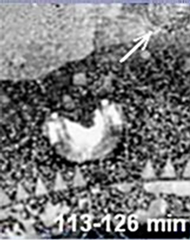
Figure 19. Large object “disk”, 0.34 m in diameter, is visible right at the top of the image (seen is lower part of the round feature).
elongated structure resembling a broom. Again the chosen fragments of sequential images are presented as a temporal sequence of frames. Figure 20 shows a sequence of images of “disk” (arrow a) and its surroundings. At the bottom of each frame time of the passage of the “disk” image by the scanner is provided.
In the first two frames of Figure 20 (time 32 and 72 min) the shape of “disk” and “broom” almost do not change. A short arc at the bottom of the “disc” is seen in the first two frames. In frame (86 min) the arc lengthened by several times, and the “disk” was divided into fragments. In the next frame (93 min), instead of the “disk” the symmetrical bright object (arrow b) appeared of about the same size and of a regular shape. It is formed by numerous angular folds, such as chevrons. The orientation of the “chevrons” lines is other than of the “broom”. From the bottom of the “chevron” many arcs are detached having the form, like a single arc on the 86 minute frame. They are arranged one after another and cover down an entire surface, adjacent to the camera’s lid. “Disk” on the frame 93 minute is not seen. Different from the “broom”, under the “chevron’s” edge a shadow is visible, which indicates that the “chevrons” are prominent above the surface.
26 minutes later, on the last frame of Figure 20 (119 min), the “disk” and “broom” fully recovered, and “chevron” and arcs disappeared without any trace. It is possible that some objects moved beyond the upper limit of the image. “Disk” on the last frame is seen most clearly.
Thus, Figure 20 covers a full cycle of changes in shape of the “disk”. Apparently, the “chevrons” are somehow connected with arcs and the “disk”. However, the author has not a slightest notion what all this performance means. Still more difficult is explaining what means a large, about 0.6 m body, all made of arcs, below the “chevrons”, appearing in the 93 min frame.
5.2. “The Black Rag”
“The black rag” appeared around the cone for measuring mechanical properties of the soil (Figure 21). At the side

Figure 20. Changes in the position and shape of the “disk” (arrow a), and “chevron” (arrow b). The approximate time of imaging of the “disk” by the scanner is indicated in each frame.

Figure 21. The unknown object “the black rag” originated within the first 13 minutes after landing around the conical measuring hammer which had partly penetrated into the soil. The details of the mechanism can be seen through the black object which indicates its semi-transparency. Subsequent images (obtained in the period from 27 to 50 minutes after landing) show a clean surface of the conical hammer, the object “the black rag” disappeared.
of the VENERA-13 camera 2, there was an instrument for measuring mechanical properties of the soil [34].
The length of the farm was 600 mm. Since the overall objectives of the mission included the analysis of minor constituents of the atmosphere and soil, the presence of any organic charring material on the instrument and on the outer parts of the lander was excluded, same as detach of any films from the lander. During laboratory tests these conditions received much attention. After landing, the scanning cameras’ lids (the large white semi-cylindrical detail on the image Figure 20) were thrown off by means of pyro cartridges. At the same time several other instruments were opening up. In the first image of Figure 21 (obtained in the period of 0 - 13 minutes after landing) one can see that a vertically elongated black object of unknown origin, “a black rag”, measuring about 60 - 80 mm in height, emerged, wrapping along its full height the measuring cone (for soil mechanical properties measurements). On the two subsequent images taken in 27 and 36 minutes respectively, the object disappeared without a trace. From a comparison with other entities discussed elsewhere, one possible explanation may be that the appearance of the black object has something to do with destruction of soil crust by the measuring cone and some gaseous media appearing from there, condensing on the surface of still relatively cold measuring cone. When getting hotter the condensed media evaporated from the cone. There is no explanation, why it condensed on the cone only. The object cannot be a defect of the panorama: Figure 21 shows that the details of the mechanism are projected onto the object, and some details of the mechanism are partially visible through the “rag”.
6. Hypothetical Flora
The possible existence of life at conditions similar to the oxygenless CO2—atmosphere of Venus, having moderately high temperatures (735 K), was repeatedly considered in many papers [e.g., 35 - 39 and others]. Their authors conclude that the possibility to meet life on Venus is not excluded [36], for instance, life in its microbial forms flows high in the atmosphere. There is also a possibility that life evolved from the early stages of the history of the planet accommodating to slowly changing conditions.
When the temperature of ingoing radiation is T1 and of the outgoing radiation T2, the thermodynamic efficiency of the process , regardless of the specific biophysical mechanism acting on the surface of Venus, and should be somewhat below that of Earth, as T2 = 290 K for Earth and T2 = 735 K for Venus. In addition, because of the strong absorption of the blue-violet rays in the atmosphere, the maximum solar radiation on Venus is shifted to the green-orange region and according to Wien’s law corresponds to lower effective temperature T1 = 4900 K, when T1 = 5770 K for Earth (In this respect, Mars has the best conditions for life).
The 725 - 755 K temperature range near the planet’s surface is, of course, absolutely incompatible with terrestrial forms of life, but if one thinks about it, it is thermodynamically no worse than the terrestrial conditions. True, the media and the existing chemical agents are unknown, but no one has looked for them. Chemical reactions at high temperatures are very active, and initial materials on Venus differ little from those on Earth. There are many anaerobic mechanisms known in biophysics. Photosynthesis in a number of prokaryotes is based on the reaction where the electrons donor is hydrogen sulfide, H2S, not water. A number of autotrophic prokaryotes living deep under ground, use chemosynthesis instead of photosynthesis, for example, . It seems that there are no physical prohibitions for life at high temperatures [26]. Of course, photosynthesis at high temperatures and in oxygenless environment must, apparently, rely on completely different, unknown biophysical mechanisms, mentioned by B. W. Jones [40].
But what sources of energy, in principle, could be used by fauna in the high temperature oxygenless atmosphere, with sulfur components as main agents for meteorology? The objects discussed in sections above are large enough, they are not microorganisms. It is most natural to assume that, like on Earth, Venusian fauna is heterotrophic, and the source of its energy is hypothetical autotrophic flora. Despite the fact that the direct rays of the Sun, as a rule, do not reach the surface of the planet, there is enough light for photosynthesis. In the case of terrestrial flora scattered light around 0.5 - 7 klx is quite sufficient for photosynthesis. The measured sunlight on Venus is of the same order, within 0.5 - 9 klx [21].
In contrary to data about fauna on Venus, the data available in VENERA landers images is insufficient to judge about its flora. Nevertheless two possible patterns of the planet’s flora have been found. An object in Figure 22 may be a stalk with few leaves on it. The “stalk” stands vertically and casts a shadow. A poor resolution of the image does not permit its improving by processing anymore.
Still more interesting is an object presented in Figure 23, similar in its shape to Earth’ mushrooms. It is placed in foreground, about 15 cm from the lander’s buffer and is elevated for 2 - 3 cm above the ground. It gets visible in all successive VENERA-13 panoramas after their new processing. The “mushroom” is the brightest feature in the area shadowed a bit by the lander’s body. The color image in Figure 23 is made of 3 panoramas. When all 6 images were processed by the correlative stacking method, 3 black and white versions of the image were produced (inset in Figure 23). A radial structure of the object is seen in all of them. The “mushroom” is comparable in size to hesperos. It could be attributing to hypothetical flora of Venus. No movement of the object was detected during 1.5 hours. The “mushroom” is one more terramorphic object in hypothetical Venusian life forms.
7. Acoustic Experiment on VENERA-13, -14
As the planet’s atmosphere is extremely dense the field of acoustic signals may carry important information about the activity of hypothetical Venus’s fauna. In the missions of 1982 there was an acoustic experiment among other investigations. Acoustic detectors (microphone of electromagnetic type with a metal membrane)
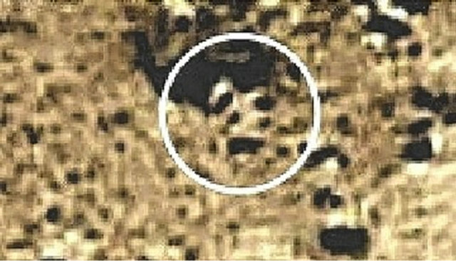
Figure 22. Result of looking for possible flora on Venus. It seems the unknown object may be a stalk with few leaves. Its height is about 12 - 15 cm. There is a shadow below it. VENERA-9.

Figure 23. Fragment of the VENERA-13 panorama with an object reminding a mushroom. The size of it is about 8 cm. At the inset 3 different versions of the joint processing of 6 fragments are presented.
were a part of the instrument GROZA on VENERA-13 and -14 landers [41]. The microphones were situated outside the lander, close to the ground (at a height of about 14 cm). Together with an amplifier the microphone’s spectral characteristic (at the level of 0.5) covered the range from 0.3 to 4 kHz (when at a cold state) and shifted towards low frequencies at operational temperatures. The microphone’s operability was tested and was maintained up to the level of 500˚C. Limited telemetry possibilities afforded transmission of solely the data concerning signal level. Sounds were registered during a descent in the atmosphere, then for 240 s after landing and then during short 8 seconds intervals repeated by turns every 200 and 392 sec. Telemetry sampling frequency was 2.5 Hz and did not change. This was a pioneering experiment and it did not seem possible to forecast correctly alteration of the microphone’s sensitiveity under the conditions of Venus. Therefore, VENERA-13 lander was equipped with high sound channel sensitivity and VENERA-14 with low sensitivity. As it was reported in the work [30], at VENERA-13 the signal of the sound experiment had been at saturation before the 87th min (the beginning of the panorama V-13-1-6 BW scanning) and there had been the data available over the past 992 sec. However, in 2010 when the initial data were checked, it turned out to be that in reality there had been no saturation (as is shown).
The results are shown in Figure 24. In the right part of the picture one can see the results obtained by VENERA-14 in 3200 sec. The results of the sound experiment were first used in measuring the speed of the wind at the landing sites of VENERA-13 and -14. For this purpose, a sister instrument was placed in an aerodynamic tunnel in Lomonosov Moscow State University and then a calibration for speed and incident wind angle was performed. Then that the results were re-scaled over according to the conditions on Venus. In the left part of Figure 24 one can see calibration diagrams (in this way wind speed on Venus of 0.4 m/sec was obtained). However, besides wind noise, other noises were registered in the experiment. Initially, the probe was producing great noise, pyro cartridges were released [42] and a drilling machine with pyrotechnic mechanisms was operating [43]. Noise level reached approximately 93 dB.
More detailed data of the sound experiment are presented in Figure 25 by the fragment of VENERA-13 data (from the 28th to the 33rd min). The main noisy operations of the lander concluded in 20 min. The peak of more than 75 dB observed at the 31st min is most proba-

Figure 24. Results of acoustic experiments onboard the VENERA-13 and -14 probes (1982). At the left—calibration curves for the microphone as the device for wind measuring; at the right—sound channel output signal (VENERA-14). Horizontal axis—the time since landing. After 240 s the data were transmitted only in 8 sec intervals every 200 and 392 sec. The output signal was 70 dB in tranquil regime and reached 93 dB from noise produced by the lander itself.
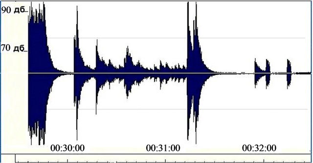
Figure 25. Detailed results of the acoustic experiment onboard the VENERA-13 probe (1982) in 30 - 33 min interval. Landing was at 00:29:36. Exponential decline of output signal trailing edge of a sound channel is explained by the properties of the electronic device output and is not connected with the characteristics of the sound source.
bly connected with the lander. Later measurements (below 66 - 70 dB) relate to the atmosphere of Venus. The origin of the last peaks is unknown. It can be connected with the wind noise. No significant signal variations were detected that could be related to the assumed fauna activity. However, the results cannot be regarded as representative due to such short survey intervals and long “deaf” intervals.
More detailed data (signal variations during 8 sec intervals, as is shown in Figure 25) have not been published. Acoustic measurements can become an important experiment for searching signs of Venus’s fauna. If it really exists sound effects produced by it should be observed.
8. Conclusions
Interesting objects were observed in the last 40 minutes of the lander’s work by the camera V-13-1 of the VENERA-13 lander, in series 6 (the images V-13-1-6 BW and G). The presented analysis of the images of the Venus’ surface is based on a sequence of nine panoramas of the camera V-13-1, which were obtained sequentially during extra long period 2 hours 6 min, and on the VENERA-9 and VENERA-14 panoramas.
Objects found in the investigation varied. All of them are rather large, from 8 - 9 cm up to half meter. Smaller objects were not resolved by scanning cameras. At the distance 3 - 4 m detail of even large objects remain unresolved, again because of the limited resolution of the cameras. In 4 or 5 cases observed objects show signs of movement or motion, in other cases they remain fixed for the whole duration of the observation. There is reason to assume that if the fauna of Venus is real, its movements are very slow, about 1 mm/s, even in extremly dangerous conditions. One group of objects (with a given nickname “hesperus”) having characteristic shapes and sizes (20 - 30 cm) was observed at three different landing sites at Venus, separated by distances of 900 and 4500 km. Apparently they are widely distributed across the planet. Some objects are so much terramorphy that one may think about the yet unknown universal biophysical laws. However, in some cases, the observed objects are so strange that there is no guess about their nature.
Assuming that the hypothetical fauna Venus must be heterotrophic, one can suppose that in its existence, it must be based on autotrophic flora. Hypothetical patterns of flora of Venus also are seen in the pictures of its surface. The most natural source of energy for flora may be photosynthesis, but based on the absolutely unknown mechanism. Measurements show that there is enough light on the surface for photosynthesis (by terrestrial standards).
The paper does not propose any suggestion about the biophysics of the fauna and flora of Venus that could exist in the waterless and oxygenless conditions, at temperatures of 460˚C. Nevertheless specialists in biophysics suppose that such kind of life could be possible [26,40]. Strange however, looking for it until now hardly came to anyone’s mind.
Scanning cameras of the VENERA-9, -10 and VENERA-13, -14 were intended to produce a general notion about the planet’s surface and did not anticipate problems finding possible inhabitants of Venus. The special mission, if it ever takes place, should be significantly more complex. Before such mission takes place neither proves nor could denials for life on Venus be justified.
9. Acknowledgements
The author thanks for a value help and support in the images analysis the leading authors of all the Venus TV-experiments, Dr. A. S. Selivanov and Dr. Yu M. Gektin [27]. The paper wins after important remarks made by Dr. V. D. Shiltsev and Dr. G. I. Merzon. There were many discussions with Dr. Yu M. Gektin. The paper should be concluded with his statement: “We don’t like the idea of life present on Venus. However we are not able to find any other explanation to what we see in panoramas”.
The paper in its different parts has been translated by Dr. K. Bronnikov, Dr. G. Merzon, O. Odintsova and the author.
REFERENCES
- I. Baraffe, G. Chabrier and T. Barman, “The Physical Properties of Extrasolar Planets,” Reports on Progress in Physics, Vol. 73, No. 1, 2010. doi:10.1088/0034-4885/73/1/016901
- H. Klahr and W. Brandner, “Planet Formation: Theory, Observation, and Experiments,” Cambridge University Press, Cambridge, 2006. doi:10.1017/CBO9780511536571
- L. V. Ksanfomality, “On the Nature of the Object HD 209458b: Conclusions Drawn from Comparison of Experimental and Theoretical Data,” Solar System Research, Vol. 38, No. 4, 2004, p. 200.
- A. D. Kuzmin and M. Ya Marov, “Fizika Planety Venera (The Venus Physics),” Nauka, Moscow, 1974.
- L. Colin, “Basic Facts about Venus,” In: D. M. Hunten, L. Colin, T. M. Donahue and V. I. Moroz, Eds., Venus, University of Arizona Press, Tucson, 1983, Chapter 2.
- D. M. Hunten, L. Colin, T. M. Donahue and V. I. Moroz, “Venus,” University of Arizona Press, Tucson, 1983.
- L. V. Ksanfomality, “Planeta Venera (The Planet Venus),” Fizmatlit, Moscow, 1985.
- M. V. Keldysh, “The First Panoramas of the Surface of Venus,” NAUKA, Moscow, 1979.
- V. S. Avduevsky, A. G. Godnev, Yu V. Zakharov, et al., “Estimation of Physical-Mechanic Properties of the Venusian Soil at Landing of the VENERA-13, -14,” Kosmicheskiye Issledovaniya, Vol. 21, No. 3, 1983, pp. 331-350.
- A.S. Selivanov, V. P. Chemodanov, M. K. Naraeva, et al., “TV Experiment on the Venus Surface,” Kosmicheskiye Issledovaniya, Vol. 14, No. 5, 1976, pp. 674-677.
- A. S. Selivanov, A. S. Panfilov, M. K. Naraeva, et al., “Photometric Processing of the Venusian Surface Panoramas,” In: M. V. Keldysh, Ed., Pervye Panoramy Poverkhnosti Venery (First Panoramas of the Venus Surface), Nauka, Moscow, 1979, pp. 68-79.
- A. S. Selivanov, Yu M. Gektin, M. A. Gerasimov, et al., “Continuation of the TV Investigation of Venus Surface by Means of Landers,” Kosmicheskiye Issledovaniya, Vol. 21, No. 2, 1983, pp. 176-182.
- A. S. Selivanov, Yu M. Gektin, M. K. Naraeva, et al., “On Dynamic Phenomena Detected on the Venusian Surface Panoramas Obtained by the VENERA-13, -14 Landers,” Kosmicheskiye Issledovaniya, Vol. 21, No. 2, 1983, pp. 200-204.
- I. M. Bokshtein, M. A. Kronrod, P. A. Chochia and Yu M. Gektin, “Processing of TV Panoramas of the Venus Transmitted by VENERA-13, -14,” Kosmicheskiye Issledovaniya, Vol. 21, No. 2, 1983, pp. 190-200.
- M. Ya Marov, B. V. Byvshev, I. P. Baranov, et al., “Nephelometric Investigation of Venus Clouds by Means of VENERA-13, -14,” Kosmicheskiye Issledovaniya, Vol. 21, No. 2, 1983, pp. 269-278.
- K. P. Florenskiy, A. T. Bazilevskiy, G. A. Burba, et al., “Panorama of Venera-9 and -10 Landing Sites,” In: D. M. Hunten, L. Colin, T. M. Donahue and V. I. Moroz, Eds., Venus, University of Arizona Press, Tucson, 1983, Chapter 8.
- L.V. Ksanfomality, “Planety, Otkrytye Zanovo (Planets Discovered Anew),” Nauka, Moscow, 1978.
- B. E. Moshkin, A. P. Economov, V. I. Moroz, et al., “Spectrophotometric Experiment on VENERA-13, -14 Landers,” Kosmicheskiye Issledovaniya, Vol. 21, No. 2, 1983, pp. 236-245.
- L. V. Ksanfomality, “The Surface of Mercury in the 210-350 W Longitude Range,” Icarus, Vol. 200, No. 2, 2009, pp. 367-373. doi:10.1016/j.icarus.2008.12.007
- L. V. Ksanfomality, “Results of the New Processing of Images Obtained from the Surface of Venus in a TV Experiment Onboard the VENERA-9 Lander (1975),” Solar System Research, Vol. 46, No. 5, 2012, pp. 364-373. doi:10.1134/S0038094612050061
- L. V. Ksanfomality, “Venus as a Natural Laboratory for Search of Life in High Temperature Conditions: Events on the Planet on March 1, 1982,” Solar System Research, Vol. 46, No. 1, 2012, pp. 41-53. doi:10.1134/S0038094612010042
- Yu S. Tyuflin and L. M. Kadnichanskaya, “Analytical Processing of the Venus Surface TV Panoramas for Digital Models of Areas,” In: M. V. Keldysh, Ed., Pervye Panoramy Poverkhnosti Venery (First Panoramas of the Venus Surface), Nauka, Moscow, 1979, pp. 63-68.
- K. P. Florenskiy, A. T. Bazilevskii, A. A. Pronin and G. A. Burba, “Geological-Morphology Analysis of the Venus Panoramas,” In: M. V. Keldysh, Ed., Pervye Panoramy Poverkhnosti Venery (First Panoramas of the Venus Surface), Nauka, Moscow, 1979, pp. 107-127.
- A. T. Basilevsky, “Analysis of Suspicious Objects on TV-Panorama Obtained by VENERA-9,” Solar System Research, Vol. 46, No. 1, 2012, pp. 404-408.
- D. P. Mitchell, “Anomalies in Video Transmission from Venera-13 Are Probably Not Life Forms,” Solar System Research, Vol. 46, No. 5, 2012, pp. 412-314. doi:10.1134/S0038094612050036
- A. S. Spirin, “Comment to the Article L. V. Ksanfomality ‘Venus as a Natural Laboratory for Search of Life in High Temperature Conditions: Events on the Planet on March 1, 1982’,” Solar System Research, Vol. 46, No. 5, 2012, p. 411. doi:10.1134/S0038094612050103
- A. S. Spirin, “Comment to the Article L. V. Ksanfomality ‘Venus as a Natural Laboratory for Search of Life in High Temperature Conditions: Events on the Planet on March 1, 1982’,” Solar System Research, Vol. 46, No. 5, 2012, p. 415.
- G. A. Avanesov, “Is There Life on Venus?” Solar System Research, Vol. 46, No. 5, 2012, pp. 379-380. doi:10.1134/S0038094612050012
- A. S. Spirin, “Comment to the Article L. V. Ksanfomality ‘Venus as a Natural Laboratory for Search of Life in High Temperature Conditions: Events on the Planet on March 1, 1982’,” Solar System Research, Vol. 46, No. 5, 2012, p. 386. doi:10.1134/S0038094612050115
- L. V. Ksanfomality, N. V. Goroshkova and V. K. Khondirev, “Wind Velocity at the Venus Surface Obtained by Means of Acoustic Measurements,” Kosmicheskiye Issledovaniya, Vol. 21, No. 2, 1983, pp. 218-224.
- V. V. Kerzhanovich, N. M. Ancibor, V. D. Kustodiyev, et al., “Vertical Profiles of the Wind in Venus Atmosphere by Means of Doppler Measurements of VENERA-13, -14,” Kosmicheskiye Issledovaniya, Vol. 21, No. 3, 1983, pp. 211-217.
- L. V. Ksanfomality, “Mobility and Other Features of Hypothetical Venusian Fauna,” Doklady Physics, Vol. 57, No. 12, 2012, pp. 497-501. doi:10.1134/S1028335812120014
- L. V. Ksanfomality, “Hesperos: Unusual Objects on the Surface of the Planet Venus According to Data of Missions of 1975-1982,” Doklady Physics, Vol. 57, No. 11, 2012, pp. 455-459. doi:10.1134/S102833581211002X
- A. L. Kemurdzhian, P. N. Brodskii, V. V. Gromov, et al., “Preliminary Results of Determination of Physical-Mechanic Properties of the Venusian Soil by VENERA-13, -14,” Kosmicheskiye Issledovaniya, Vol. 21, No. 3, 1983, pp. 323-330.
- S. L. Miller and J. L. Bada “Submarine Hot Springs and the Origin of Life,” Nature, Vol. 334, 1988, pp. 609-611. doi:10.1038/334609a0
- C. S. Cockell, “Life on Venus,” Planetary and Space Science, Vol. 47, No. 12, 1999, pp. 1487-1501. doi:10.1016/S0032-0633(99)00036-7
- L. V. Ksanfomality, “Extrasolar Planets and Planets of the Solar Systems: Looking for Life beyond the Earth,” Proceedings of the SPIE, Vol. 4939, 2003, pp. 169-173. doi:10.1117/12.486690
- D. Schulze-Makuch, D. H. Grinspoon, O. Abbas, L. N. Irwin and M. A. Bullock, “A Sulfur-Based Survival Strategy for Putative Phototrophic Life in the Venusian Atmosphere,” Astrobiology, Vol. 4, No. 1, 2004, pp. 11- 18. doi:10.1089/153110704773600203
- H. Lammer, J. H. Bredehöft, A. Coustenis, et al., “What Makes a Planet Habitable?” The Astronomy and Astrophysics Review, Vol. 17, No. 2, 2009, pp. 181-249. doi:10.1007/s00159-009-0019-z
- B. W. Jones “Life in the Solar System and Beyond,” Springer, Chichester, 2004.
- L. V. Ksanfomality, F. L. Scarf and W. W. L. Taylor, “The Electrical Activity of the Atmosphere of Venus,” In: D. M. Hunten, L. Colin, T. M. Donahue and V.I. Moroz, Eds., Venus, University of Arizona Press, Tucson, 1983, Chapter 17.
- A. M. Baklunov, V. P. Karyagin, V. M. Kovtunenko, et al., “Automatic Interplanetary Stations VENERA-13, -14,” Kosmicheskiye Issledovaniya, Vol. 21, No. 2, 1983, pp. 151-153.
- I. V. Barmin and A. A. Shevchenko, “Soil Collection Unit of the VENERA-13, -14 Landers,” Kosmicheskiye Issledovaniya, Vol. 21, No. 2, 1983, pp. 171-175.
- M. Ya Marov, “Illumination on the Venus Surface Measured by Automated Interplanetary Station Venera-8,” In: M. V. Keldysh, Ed., Pervye Panoramy Poverkhnosti Venery (First Panoramas of the Venus Surface), Nauka, Moscow, 1979, pp. 80-106.
Appendix: Television Experiments on VENERA-9, -10, -13, -14.
The first images of Venus’ solid surface were transmitted to Earth by TV-cameras of the VENERA-9 and -10 landers, on 22 and 25 October 1975 [10,11]. Each of the landers returned one whole (Figure A1) and one fragmented panorama. (The figures’ numbered without “A” are placed in the main body of the text). The landing site of the VENERA-9 lander was 32˚N, 291˚E and of the VENERA-10 lander was 16˚N, 291˚E, both near the extensive highlands Rhea and Theia Mons.
On March 1 and 5, 1982, experiments in television photography were repeated by the landers VENERA-13 and 14 [12], yielding in 37 panoramas (Figure A2) or their fragments of the Venus surface, with both groups suitable for processing. Their landing sites were 7.5˚S, 303.5˚Е and 13˚S, 310˚Е. Over the past 30 and 37 years, no similar missions have been sent to Venus, primarily because of their extreme engineering complexity. Cameras of VENERA-9 and -10 were less sophisticated than those of VENERA-13 and 14. It should be mentioned that besides VENERA-9, -10, -13, -14 there were VENERA-11 and -12 missions (landed December 21 and 25, 1978); each lander was equipped by two scanning cameras.
Unfortunately, on both VENERA-9 and -10 only one camera opened, the lid of the second one was not released. The second camera worked fine, but the window remained closed. The problem worsened when after landing, at VENERA-11 and -12 all lids of the cameras remained closed, although the cameras continued to work.

Figure A1. Historically first images of Venus’ surface. VENERA-9 and 10, October, 1975. Figure 10 presents the VENERA-9 image after 2012 processing.
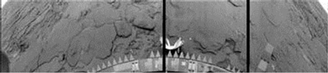
Figure A2. Black and white image of the camera 2 of VENERA-14 after the initial processing. Figure 2 presents the same image after the contemporary processing.
The VENERA-9 and -10 cameras were designed for only black-and-white TV-images [10,11]. The camera design, the images, methods of their processing and interpretation were detailed in a special edition “The first panoramas of Venusian surface” [8]. A special feature of the experiments was the use of powerful lights for the field illumination. There were two 100-Watt halogen lamps with reflectors, as there was no certainty that surface will be in good lighting conditions. The precaution was not justified. If one does not know in advance the exact sites lit artificially, it is hard enough to determine them on the panorama. The prediction for the level of the natural illumination gave a value about 9 klx [44]. Results of the TV experiment on VENERA-9 and -10 amounted to 3 to 6 klux of natural daylight.
The resolution of the VENERA-9 and -10 panoramas was 517 vertical lines at the 180˚-panorama, 115 pixels per line. The angular resolution (unit pixel) was 21 arc minute. The duration of the scan line was 3.5 s; the duration of the sweep of one panorama was 30 minutes. At that time CCD detectors still were at their laboratory stage and the light detector was photomultiplier FEU-114 (developed by the G. S. Vildgrube team). The shape of the spectral sensitivity was characteristic for a multialkali photocathode (Figure A3A).
To protect the camera from the penetrating thermal radiation a scanning mirror was placed at the top of the periscope system (Figure A4). The tilt of the optical axis of the scanner to the vertical was 50˚; the input of the optical systems was located at a height of 82 cm above the landing plane. The actual VENERA-9 panorama covered 174˚, the duration of its real time transmission and recording was 29.3 min. Then the right side of the panorama was repeatedly scanned within 124˚.
The VENERA-9 and -10 landers worked on the Venus surface for 50 min and 44.5 min, respectively, with the granted duration of the TV cameras functioning 30 min. The VENERA-10 panorama coverage was 184˚, and then two fragments were repeated at the beginning and end of the image, 63 and 17˚. The image was coded in a 6-bit (64 levels) system and transmitted through an omni-directional antenna of the lander transmitter to the orbiter (a satellite in the 48-hour orbit) and relayed in

Figure A3. Spectral sensitivity of cameras VENERA-9, -10 (A) and of cameras VENERA-13, -14 (B).

Figure A4. Field of scanning cameras of VENERA-13, -14. Sizes are given in mm. The width of field for cameras of VENERA-9, -10 was 40˚ and position of the optical entrance was 820 mm. The cameras were installed on opposite sides of the lander.
real time to Earth through its narrow-beam antenna.
The noise level in the images received on Earth was low (Figure A1). However because of the limited resolution, the panoramas, in their original form, even after a complicated processing, left much to be desired.
Nevertheless the images (especially the rich in detail image from VENERA-9) permit additional, though very time-consuming processing by more modern tools.
There were many improvements in the VENERA-13 and VENERA-14 scanning cameras. They were fitted with glass filter disc. Spectral intervals (Figure A3B) were 410 - 750 nm (no filter), 390 - 510 (blue, images are almost useless), 490 - 610 (green) and 590 - 720 nm (red filter). The cameras’ optics entrance was located at a height of 90 cm above the surface, on both opposite sides of the lander (Figure A5). The inclination of the camera’s axis (50˚) allowed to discern millimeters-sized features of the surface in close proximity to the lander, and about 10 m at the mathematical horizon (at a distance of 3.3 km on a flat surface).
The inclination of the camera’s axis distorts images; patterns of the corrected image are presented in Figures 2 and 10. New calculation of the VENERA-13 panorama’s geometry has been fulfilled by B. E. Moshkin (non published). It permits converting of panorama to the photo plan, details of which have equal scale. A central fragment of the photo plan is shown in Figure A6.
As distinct from traditional television systems, the images produced by each VENERA cameras were panoramic (a horizontal field of about 180˚), with lines oriented vertically having a resolution of 211 pixels on the active part and 252 pixels per line, including housekeeping, two times more then at VENERA-9 and -10. The angular pixel size was 11 arc min. One line took 780 ms

Figure A5. VENERA-13 lander at laboratory testing. The TV camera window is placed just above the CCCP inscription.
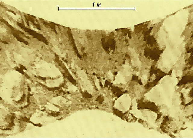
Figure A6. Photoplan of the central part of the VENERA-9 panorama. The photoplan is convenient as it shows all detais at equal scale.
(3.1 ms/pixel). The images consisted of 1000 lines and were transmitted by a radio transmitter’s omni-directional antenna (a spiral at the top of the picture Figure A5) to the satellite located in the elliptical orbit. The satellite relayed the data from the lander to terrestrial receiving stations in real time.
Due to high efficiency of thermal protection the rise of the landers’ temperature was fairly slow, despite high ambient temperature [42]. On March 1, 1982 the camera 1 of the lander VENERA-13 was operating during record long time, 1 hour 40 minutes, as reported officially. If one considers all the data, including those with an increased noise the signals were being received by the orbiter for more than 2 hours (126 minutes; or for 139 min, according to M. Yu Gektin, one of authors of the TV experiment). It would have continued, and still worked, but approximately at 127 minutes, it is not clear who and why, sent a command from Earth, ordered to stop receiving data on orbiter, while the lander continued to send its signals... One can assume that this was a concern for the orbiter’s battery discharge or something else, but was not a priority the lander? The total duration of the camera V-13-2 operation was shorter, 60 min.
Next there are some details about VENERA-13 results. As is shown in Table 1 the total number of collected full images is 10 (the last blue image is not accessible). Normally the loss of radio communications between the lander and orbiter was ultimately caused by orbiter’s dipping beyond the horizon. Nevertheless disturbance in the operation of the dangerously overheated radio system had been observed sporadically long before the connection was completely lost. It is not improbable that short time losses of data occurred also because of a physical effect of an unknown nature in the Venusian atmosphere which had been observed several times during the work of earlier Soviet and American spacecrafts [7, ch. VI]. Scanning of a single panorama made by VENERA-13 and its simultaneous transfer took 13 minutes. The ADC used 9 bit encoding (TIFF format, with bit #10 used for housekeeping). The cameras’ designation as V-13-1 and V-13-2, and the panoramas’ denotation (like 1, 2, 6 and 3, 4, 5, respectively) were used in the data submitted by the authors of the TV experiment to the US research group at the Brown University and published by them. These symbols are saved in the paper. In the first series (V-13-1-1), with very low noise, the transfer of the first black-and-white image was succeeded by transmission of a red, green and blue image, and then again a blackand-white image came. (In the text they are denoted as V-13-1-1 BW1, R, G, B and BW2 respectively). Thus, each pixel of the VENERA-13 images was repeated several times during scanning, as shown in Table 1.
In the second set, with a good signal level, with low noise, partly shortened versions of the red and green panoramas (V-13-1-2, R and G) were transmitted; however, some of their parts still were lost due to the sudden noise (Figure A7). When processed they were replaced by the same parts taken from other images. After completing the second series, the camera and the radio link, of course, did not shut down and continued to work. In the third series (V-13-1-6), black-and-white, red, green and blue images were transmitted (Table 1), all with different types and level of noise. A similar sequence, with minor differences (with a reduced color image sectors length) was transmitted by the second camera, V-13-2. It included series 3, 4, 5. The images obtained in the blue spectral region were almost useless, because the blue rays are almost completely blocked by the Venus’ atmosphere.
Along with the video information, the radio link transmitted the data from the other devices. For this purpose periodically, every 192 and 384 s, 10 - 11 lines of an image were filled with other telemetry information (the narrow vertical bar in the left side of Figure A7). The published colorful panoramas made by camera 1 [12] are based on the data of the first and partly of the second series (V-13-1-1, V-13-1-2). For the synthesis of color images, that was enough. The third series 6, with an increased noise level, was not used in the published images.
Analysis of the nature of noise in the images of the series 6 has not been given by the experiment’s authors. Basing on the analysis of the images and private discussions with the authors of the experiment it can be assumed that there were at least three different types of noise. In series V-13-1-2 (red and green images) interference from other devices and instruments appeared, as if the wrong signals were penetrating somehow through the commutator to the transmitter’s modulator (Figure A7). In the third series (#6), in the red and green panoramas V-13-1-6, there is a noise over the dark patterns, but the alight elements remain clean. This may mean, for example, the shift of the ADC zero level (perhaps to a greater extent for the red, less for the green), because of the lander’s overheating at the end of the mission. In the black-and-white V-13-1-6 panorama the interference also appears, however, of another origin—white dots (Figures 12 and A8). The image was transmitted in negative, so instant signal loss or attenuation (for some unknown reasons) at the orbiter’s receiver input was equivalent to a bright dot. Of course, this is only a possible explanation.
Table 1. VENERA-13 images and timing after landing.


Figure A7. The original image V-13-1-2 G with lost lines (top) and its processed version (below) where the affected areas of the image are replaced by V-13-1-1 G fragments.

Figure A8. Different level of noise in panoramas of the VENERA-13 lander: two first BW images (series 1 and 2) and all last panoramas of series 6.
Figure A8 presents a comparison of noise on two first BW images and three panoramas of the series 6 (BW, R and G).
It should be noted that when relaying through the VENERA-13 orbiter the data were saved in its memory and subsequently transmitted again to the Earth (repeatedly). At that, different designations were used for them, including V-13-1-1 (different from V-13-1-1 mentioned above). One can avoid confusion either by differences in image content (for example, in the changes of dust location on the landing buffer), or more strictly, by the telemetry insertions content. Though the positions of the insert’s headers are identical, their content varies.
An example of images processing has been demonstrated in Section 3. The most important processing procedure was correlation stacking of number of images. Various types of software for correlation stacking have been tested. Strange enough: the simpler the program, the better the result. Different processing software have been used: AIMAP 225 (designed by V. Kakhiani, unpublished), Astro Stack 1 (designed by R. Stekelenburg, 2000), standard WINDOWS programs (PHOTO EDITOR and PAINT) and short self made software. The programs were combined and used in a multilevel (hierarchical) mode: groups of selected initial pictures were exposed to correlation stacking of the first level then the same operation was applied to their results.