Advances in Chemical Engineering and Science
Vol. 2 No. 1 (2012) , Article ID: 16708 , 13 pages DOI:10.4236/aces.2012.21007
Simulation of CO2 and H2S Removal Using Methanol in Hollow Fiber Membrane Gas Absorber (HFMGA)
1Department of Chemical Engineering, University of Sistan and Baluchestan, Zahedan, Iran
2Department of Chemical Engineering, Ferdowsi University of Mashhad, Mashhad, Iran
Email: *h.ateshi@ hamoon.usb.ac.ir, majid_mahdavian@yahoo.com
Received September 1, 2011; revised October 25, 2011; accepted November 10, 2011
Keywords: Computational Mass Transfer (CMT); Membrane Gas Absorber; CO2 and H2S Separation; Physical Absorption; Methanol
ABSTRACT
Application of methanol solvent for physical absorption of CO2 and H2S from CO2/H2S/CH4 mixture in gas-liquid hollow fiber membrane gas absorber (HFMGA) was investigated. A computational mass transfer (CMT) model for simulation of HFMGA in the case of simultaneous separation of CO2 and H2S was developed. The membrane gas absorber model explicitly calculates for the rates of mass transfer through the membrane and components concentration profiles. Due to the lack of experimental data in the literature, the model was validated using available individual components’ water absorption data. The numerical predictions were in good agreement with the experimental data. The effects of operating conditions such as liquid velocity, gas velocity, temperature and pressure were analyzed. It is shown that methanol solvent can successfully be used for CO2 and H2S removal in membrane gas absorber. Also it is found that the concentration distribution of CO2 and H2S in the gas phase along the fiber length obeys plug flow model whereas in the methanol absorbent deeply affected by the interface concentration, absorbent velocity and diffusivity. In addition, it is shown that application of membrane gas absorber using methanol absorbents for H2S removal and at higher flow rate is more efficient. Moreover, at operating pressures above 10 atm even at low absorbent rate, H2S concentration depletion is relatively complete while at 1 atm this value is about 30%. This means that removal efficiency decreases with an increase in temperature and it is more important especially for H2S.
1. Introduction
Some industrial gas streams (such as natural gas processing, petroleum refineries, petrochemicals) frequently contain H2S and CO2 as impurities. All of these gases requires treatment before delivery to the pipeline. It is reported that CO2 is representing about 80% of greenhouse gases and half of the CO2 emissions are produced by industrial plants such as fossil-fuel-fired power plants, iron, steel and cement works [1]. Also carbon dioxide is a common contaminant of natural gas and must be removed to a level of <8% (usually <2%) to minimize corrosion of the pipeline. Hydrogen sulfide removal is also desirable to reduce corrosion. In many cases it is necessary from the health and safety standpoint [2].
The most well known technology for recovery/removal of CO2 and H2S is solvent absorption. This technology was established over 80 years ago in the chemical and oil industrials for the removal of acid gases from natural gas streams. For the removal of CO2 and H2S, traditionally absorption processes like packed and plate columns are utilized [3]. Because these generally require large space and high investment cost, the emphasis of designing most of these operations is towards maximizing the mass transfer rate by creating as much interfacial area as possible [4]. In addition, they also suffer from several limitations including flooding, loading entrainment, foaming, weeping, etc. In recent years, the demand for alternative technologies has increased and many researchers have looked for new technologies to enhance the efficiency of absorption processes. Membrane-based absorption technique has been introduced as an emerging technology for the recovery/removal of gases (like CO2, H2S, SO2, NH3, VOC, etc.) from various industrial process gas streams [5]. In addition to gas/liquid, this technology also has found applications in numerous liquid/liquid applications such as fermentation, pharmaceuticals, wastewater treatment, semiconductor manufacturing, carbonation of beverages, metal ion extraction, protein extraction, osmotic distillation and other operations [6].
Membrane gas absorbers are devices that achieve twophase mass transfer through diffusion without dispersing one phase within another. Such a device employs a porous membrane acts as a non-selective barrier between both phases where the gas and the absorbent solution flow on two sides of a membrane [5]. The membranes are usually microporous and can be both hydrophobic and hydrophilic. Hydrophobic microporous membranes like polypropylene (PP), polytetrafluoroethylene (PTFE) and polyvinylidene fluoride (PVDF) membranes have received increasing attention in recent years for using in membrane gas absorbers because of their good hydrophobicity [7]. These membrane absorber systems, generally in the form of hollow fibers with diameters of 0.5 mm - 1 mm in densely packed membrane modules, provide a high interfacial area (500 m2/m3 - 2000 m2/m3) significantly greater than most traditional absorbers (100 m2/m3 - 800 m2/m3) between two phases to achieve high overall rates of mass transfer. This significantly decreases the size required for the contactor [8]. Moreover, this kinds of contacting devices offers a number of important advantages over conventional dispersed phase contactor for gas sorption, such as large interfacial area between gas and liquid flow (up to two orders of magnitude more surface area per volume than conventional contactors), no flooding and foaming phenomena, independent control of gas and liquid flow rates, high efficiency, the possibility of combining absorption and desorption in one single compact module, energy intensive, and so on (as an example of review, see Gabelman et al. [5]).
Chemical absorbents like amines and amino acid salts are extensively used in the removal of impurities from gas mixtures. Physical absorbents have been of considerable interest in the development of gas treatment solvents, especially when the partial pressure of undesirable impurity is high. Some of the physical solvents used commercially are propylene carbonate (PC), n-formyl morpholine (NFM), dimethyl ethers of polyethylene glycol (DEPG), and n-methyl-pyrrolidone (NMP) (see more example in [9]). Physical solvents can be a possible alternative to chemical solvents in certain areas of applications, although they are less effective than chemical absorbents (i.e. the specific absorption rate into physical absorbents in comparison with chemical solvents is less). But they can be regenerated by just pressure reduction method without large amount of heat supply and thus excessive energy savings can be obtained [9]. An economical analysis must be done to select the best choice of solvent. In addition, they can be used as pre-treatment solvent in the development of hybrid systems. The most well known physical absorbent is water. However, its economics are limited by the relatively low solubility which leads to larger amounts of circulation rate, i.e. the higher investment costs as well as the higher operating costs [10]. However, there are good organic solvents which possess a much higher solvent capacity than water. Among the physical solvents, n-methyl-2-pyrrolidone (NMP), methanol and propylene carbonate (PC) are popular as gas treating solvents. Methanol has a high thermal and chemical stability, low vapor pressure, and is not corrosive. It is able to absorb acid gases, hydrocarbons, mercaptans and water. Moreover, it is produced in big quantity and readily available [10].This properties make it highly effective for processing a wide range of compositions.
The applications of hollow fiber gas-liquid membrane gas absorber for acid gas removal specially carbon dioxide from gas mixtures have been studied by several researchers. In this case, a large number of experimental absorption studies and theoretical modeling analyses have been performed with physical or chemical absorbent liquids such as pure water, aqueous amine solution, aqueous sodium hydroxide solution, aqueous potassium carbonate solution, aqueous blended solvents, etc. [11- 14]. Some authors have explored possible simultaneous removal of H2S and CO2 in hollow fiber membrane gas absorber using MEA [1] and DEA [15]. However, of the authors considering chemical absorption, few have worked with physical solvents as would be the good choice in membrane gas absorber process. There have been few attempts to address possible physical absorption in hollow fiber membrane gas absorbers [16-18] that mostly describes the water performance and theoretical analysis of simultaneous removal of CO2 and H2S using methanol absorbent in HFMGA has not been discussed by researchers.
In the present work, after modification of 2D mathematical model, this new process has been applied for CO2 and H2S capture from carbon dioxide/hydrogen sulfide/ methane mixture (when the partial pressures of CO2 and H2S are 10% of total pressure) using methanol (as an example of physical absorbent) absorbent and its potential possibility for carbon dioxide and hydrogen sulfide removal has been evaluated. It should be mentioned that areas of possible HFMGA process for gas treatment using physical solvent with economic considerations will be reported in another work. This work was performed using CFD tool with respect to solubility behavior. CFD has been largely used as a powerful tool to model membrane separation processes. It is able to simulate the concentration, temperature and velocity fields as well as the transport parameters and operating efficiency.
2. Model Development
In this paper, a steady-state two-dimensional mathematical model has been modified (e.g. [1,12]) to describe the physical absorption of carbon dioxide and hydrogen sulfide in the polymeric hollow fiber membrane gas absorber (using methanol absorbent as the absorption liquid). The model describes the mass transfer in the gas, membrane and liquid phases. Axial and radial diffusion inside the shell, through the membrane, and within the tube side of the membrane gas absorber have been considered in the model equations. It allows studying the effect of membrane wetting on the mass transfer through the membrane and also the effect of operating conditions (gas and liquid flow rates, temperature), solvent affinity (H) and flow pattern (counter current or co current arrangement) on the carbon dioxide and hydrogen sulfide removal efficiencies.
This model assumes that the fibers are distributed evenly through the shell space, which allows the results obtained with a single fiber to be generalized to the entire module. Model results are based on “non-wetted mode” in which the gas mixture filled the membrane pores.
The following assumptions are made to develop the governing mass transfer differential equations: 1) fully developed parabolic velocity profile in the hollow fiber under laminar flow conditions; 2) the mixture gases flow inside the shell are ideal gas; 3) Happel’s free surface model [19] is used to characterize the velocity profile at the shell side; 4) the physical properties of the fluid are constant; 5) the Henry’s law is applicable for gas-liquid interface; 6) no absorption of bulk and inert gases; 7) pitch and placing of the fibers are uniform; 8) no pore blockage.
2.1. Transport Model for the Hollow Fiber Membrane Gas Absorber
In order to describe the mass transfer and develop the equations of mathematical model in the hollow fiber membrane gas absorber, a material balance has been applied for a segment of a hollow fiber, as shown in Figure 1 in the shell, membrane and tube sides. Also, the computational domain used for the numerical simulation is shown in Figure 1. This model is based on the idea that two concentric cylinders are used as the model for fluid flowing out of the fibers and so only portion of fluid surrounding the fiber is considered and may be approximated as circular cross section [19] The fluid flow is described using the fully developed laminar flow model in the tube side, whereas the fluid flow in the shell side is characterized by the Happel’s free surface model.
The position r = 0 is the center of the fiber and r1, r2 and r3 are the inner, outer and Happel’s free model radii of the fiber, respectively (Figure 1). The radius of Happel’s free surface model is calculated to be r3 = 720 μm. Dimensions of the hollow-fiber membrane gas absorber are listed in Table 1. The gas mixture consists of carbon dioxide, hydrogen sulfide and methane is fed to the shell side at z = L, while the liquid (methanol) is passed through the tube side at z = 0. Carbon dioxide and hydrogen sulfide are removed from the mixture by diffusing through the membrane due to a concentration gradient and then absorbing with the solvent.
2.1.1. Equations Describing the Shell Side
Convective-diffusion equation for the component i using Fick’s law of diffusion, when chemical reaction is taking place, can be written as:
 (1)
(1)
where ,
,  ,
,  and
and  denote the local concentration of the component i, the diffusivity of the component i, reaction rate of the component i and axial velocity in shell side, respectively. According to the Happel’s free surface model [19], the velocity profile in the shell side may be obtained. For this purpose, a momentum balance over a thin cylindrical shell is integrated twice to obtaining the following equation for the shell side velocity distribution, which have been applied by several authors (e.g. [20,21]):
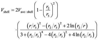 (2)
(2)
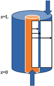
Figure 1. The schematic diagram of a hollow fiber membrane and computational domain.

Table 1. Specifications of the membrane gas absorber.
where  is the velocity component inside the shell,
  is the shell average velocity in the axial direction,
  (m) is the outer fiber radius and
  (m) is Happel’s free surface model radius defined as:
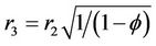 (3)
(3)
Packing density ( ) can be defined as the ratio of total surface area of membrane to the cross-sectional area of the module and
  is calculated as:
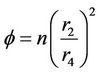 (4)
(4)
where n is the number of fibers and  is the inner radius of the MGA. The partial differential equation of the steady state mass balance for cylindrical coordinates, where no reaction takes place in the shell side is obtained and it is given as follows:
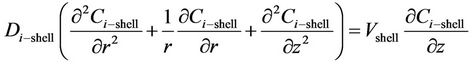 (5)
(5)
The boundary conditions are the following (i = CO2, H2S)
 (6)
(6)
 (7)
(7)
 (8)
(8)
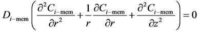
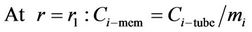
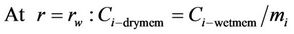
2.1.2. Equations Describing the Membrane Side
Mass transfer takes place through the membrane pores without mixing between phases and the transfer equation inside the pores can be derived without considering convection. The membrane diffusivity of species within the pores should be employed instead of the ordinary diffusivity. This parameter can be defined as . The steady state material balance for the transport of diffusing components (i = CO2, H2S) inside the membrane can be considered for non-wetting condition, where pores filled by the gas phase. For the non-wetting case, no chemical reactions will be considered in the membrane.
 (9)
(9)
 (10)
(10)
 (11)
(11)
In the partial wetted mode, additional equations are required to describe diffusion-reaction inside the wetted parts of the pores. In this case the pores are both gas and liquid-filled (wetted and non-wetted parts) and the transport of the species i generally depends on its diffusion coefficient into the liquid [22].
2.1.2.1. Non-Wetted Part of the Membrane
 (12)
(12)
Boundary conditions are:
 (13)
(13)
 (14)
(14)
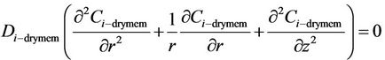
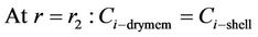
2.1.2.2. Wetted Part of the Membrane
 = 0 (15)
Boundary conditions are:
 (16)
(16)
 (17)
(17)
where  is dimensionless distribution coefficient.
2.1.3. Equations Describing the Tube Side
The partial differential equation of the steady state mass balance for each species during simultaneous mass transfer in a non-reactive absorption system is obtained and can be expressed as:
 (18)
(18)
The left-hand side of the above equation represents the diffusion and reaction terms, whereas the right-hand side is the convection term. Considering laminar flow, Navier-Stokes equations and the equation of continuity can be solved for fluid flow in a cylindrical pipe, therefore velocity distribution in the tube in the z direction can then be obtained as [22]:
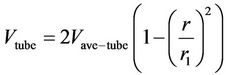 (19)
(19)
where ,
,  and
and  are the average velocity in the lumen, the radial distance and the radius of the lumen, respectively. The following boundary conditions are considered:
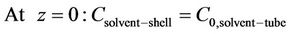 (20)
(20)
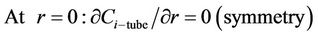 (21)
(21)
 (22)
(22)
2.2. Physical Properties and Numerical Solution
Simulation of membrane gas absorber requires data on physicochemical properties used as input parameters in the model such as solubility and diffusivity of the relevant components in each phase. The distribution coefficient of CO2 was taken from Versteeg et al. [23] and distribution coefficient of H2S was taken from Carroll et al. [24] as a function of temperature in water. Henry’s constant of CO2 and H2S for methanol as a function of temperature was reported by Lunsford et al. [25]. Liquidphase diffusivities of CO2 [23] and H2S [26] in water were estimated by the equations proposed by Versteeg and Cussler respectively and their value in methanol were estimated using the correlation given by Diaz et al. [27]. Gas-phase diffusivities of CO2 and H2S were estimated using the correlation given by Diaz et al. [27] and Cussler et al. [26]. Gas-filled membrane phase diffusivities were corrected for membrane porosity and tortuosity. The values for other data were obtained from [28,29].
In order to solve the coupled partial differential equations for the tube, membrane and shell sides with the appropriate boundary conditions and physical and chemical properties for CO2 and H2S, FEMLAB software has been used.
3. Results and Discussion
3.1. Model Validation
The model of simultaneous absorption of CO2 and H2S using methanol in hollow fiber membrane gas absorber was validated using available individual components’ absorption data of Al-Marzouqi et al. [20] and Faiz et al. [30] for physical absorption of CO2 and H2S in water, respectively, since we didn’t find any reported experimenttal data for the type of the present work in the literature.
Comparison of the experimental data and the simulated results are shown in Figures 2 and 3. It should be noted that the type of hollow fiber MGA modules and the operating conditions applied for obtaining the mentioned experimental data differ significantly with each other and we applied the exact conditions for each case. Results of both validations for physical absorption of CO2 and H2S are shown in Figures 2 and 3, respectively. Figure 2 shows the calculation of the model with the experimental results of percent CO2 removal as a function of water flow rate at the gas flow rate of 200 ml/min and Figure 3 shows the percent H2S removal and the outlet H2S concentration as a function of inlet concentration of H2S in the gas phase at gas velocity of 5.1 m/s and liquid velocity of 0.092 m/s. Clearly the model predictions are in good agreement with the two set of CO2 and H2S absorption data and it shows that the numerical model accurately predicts the experimental data for both gases.
3.2. Concentration Distribution of CO2 and H2S
A steady state component concentration distribution is

Figure 2. Comparison between experimental [20] and simulated CO2 removal efficiency.

Figure 3. Comparison between model data [30] and simulated H2S gas outlet concentration and removal efficiency.
established inside the shell, membrane, and within the tube side of the hollow fiber membrane gas absorber that affects mass transfer coefficient, removal efficiency and mass transport. Numerically calculated carbon dioxide and hydrogen sulfide concentration distribution in each of the three phases are depicted in Figures 4 and 5, respectively. In order to compare the difference between concentration profiles of CO2 and H2S effectively, equal input concentration in gas phase is applied. The solubility of CO2 and H2S in methanol is linearly proportional to their partial pressure in the gas mixture and, hence, it can be modeled according to Henry’s law. As expected, it can be seen that the concentration near the membrane-liquid wall signifycantly affected by the interface concentration, whereas the CO2 and H2S concentrations on the shell side slightly decrease in the radial direction. The concentration profile is discontinuous at the gas filled membrane-liquid interface based on the equilibrium relationship.
Due to the dimensions of the hollow fiber, the computational domain is the area of membrane length multiplied by Happel’s free surface model width. It is important to note that since the fiber is 900 times longer than its radial dimension (in this case, 0.3 mm in radius and 27 cm in length), a scaling factor of 90 has been applied in the z direction in order to reduce computational cost.
It is worth mentioning that the sensitivity grid-dependence analysis of the method of solution to the mesh size was performed in order to ensure that the numerical solution is not affected by the specification of the mesh size.

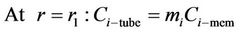
Figure 4. CO2 concentration distribution in computational do main for VL = 0.1 m/s, VG = 3 m/s and T = 298 K.
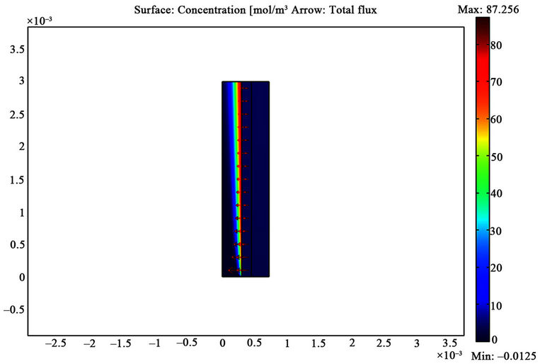
Figure 5. H2S concentration distribution in computational domain for VL = 0.1 m/s, VG = 3 m/s and T = 298 K.
The importance of a fine mesh adjacent to the membrane wall is obvious from the components concentration distribution shown in Figures 4 and 5.
Figures 6 and 7 show the numerically calculated dimensionless radial concentration profile of CO2 and H2S as a function of dimensionless length at different cross sections along fiber length, i.e. z/L = 0.1, 0.5, 0.9 (Figure 6) and at two different absorbent velocities (Figure 7). With respect to these figures, there is a concentration drop close to the absorbent-membrane interface at the membrane wall in the methanol absorbent phase for both gases. Concentration depletion for CO2 and H2S in liquid phase has the same trend but there is a sharper reduction in H2S concentration in comparison with CO2 concentration which is attributed to higher solubility of H2S in the methanol absorbent.
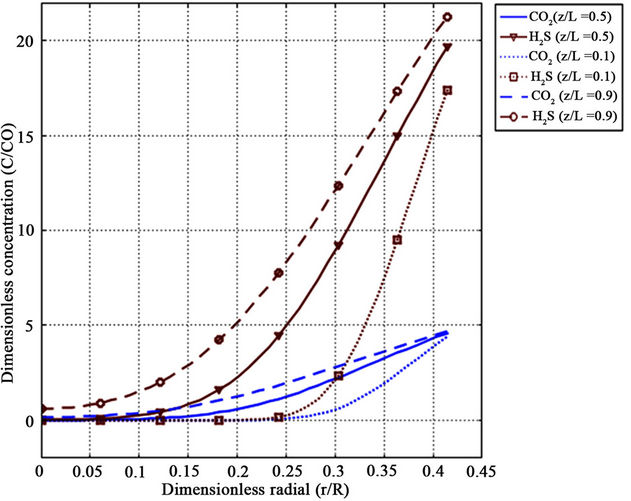
Figure 6. CO2 and H2S radial tube side concentration profiles along fiber length for z/L = 0.1, 0.5, 0.9, VL = 0.1 m/s, VG = 3 m/s and T = 298 K.
Figure 7. Effect of absorbent velocity on CO2 and H2S radial tube side concentration profiles for VG = 3 m/s, z/L = 0.5 and T = 298 K.
The results indicate that penetration depth increases with distance from methanol absorbent entrance (z/L = 0) and, therefore, components diffuse into liquid phase from membrane interface. Note that since liquid phase is very thin, it acts as film layer. With respect to the components diffusivities, liquid velocity and dimension of fiber, it is seen that the contact time is not enough that diffusion entirely affects the liquid phase and absorbed species do not distribute rapidly in radial direction before absorbent leaves the fiber (dimensionless Gz number conception). However, at higher inlet liquid velocity, the depletion of component concentration is faster. The reason is that the axial convective flow decreases with radial diffusion.
Figure 8 shows the axial CO2 and H2S concentration

Figure 8. CO2 and H2S concentration profile in the axial direction in both shell and tube sides for VL = 0.1 m/s, VG = 3 m/s,  =
=  = 4 mol/m3 and T = 298 K.
profiles in absorbent and gas phase. For absorbent phase, tube center line (r = 0) and for gas phase Happel’s radius (r = r3) is selected. It can be seen that in the case of methanol absorbent, the CO2 concentration depletion in the gas and amount of absorbed are low in comparison with the H2S. It obviously indicates the higher capacity of methanol in absorption of H2S. Based on the bulk concentration of CO2 and H2S, removal efficiencies are about 12.9% and 29.3% throughout the fiber, respecttively. Moreover, in 50% and 40% of the fiber length, the concentrations are still zero for CO2 and H2S, respectively.
3.3. Effect of Absorbent and Gas Velocity on CO2 and H2S Removal Efficiencies
Figures 9 and 10 indicate the effect of absorbent and gas velocity on the removal efficiencies of CO2 and H2S using methanol absorbent in comparison with water absorbent. Wide range of velocities was selected for both absorbent and gas in order to provide a chance to gain a real insight into this effect. Considering these figures, CO2 and H2S removal efficiencies at given conditions increase with the increase in absorbent velocity. This effect is due to the increasing in driving force with entering fresh absorbent. Therefore, CO2 and H2S concentrations in gas phase reduce and removal efficiencies improved because of higher absorption rate. This effect is reported by several authors [1,30,31] for water absorbent in the case of physical absorbent in hollow fiber membrane gas absorber devices.
The results show that with increasing the liquid velocity, the overall mass transfer coefficient increases. The reason is that in the case of physical absorption in membrane gas absorber, the controlling resistance for the mass transfer usually is liquid phase. The CO2 and H2S removal ability of methanol is illustrated in Figure 9 where the results are plotted for methanol in comparison with water absorbent. for example at the absorbent velocity of 3 m/s, the removal efficiencies using methanol absorbent are 34.7% and 84.3% and removal efficiencies using water absorbent are 13.8% and 21.6% for CO2 and H2S, respectively.

Figure 9. Effect of absorbent velocity on CO2 and H2S removal efficiencies for methanol and water absorbent at VG = 2 m/s,  =
=  = 4 mol/m3 and T = 298 K.

Figure 10. Effect of gas velocity on the CO2 and H2S removal efficiencies for methanol and water absorbent at VL = 1 m/s,  =
=  = 4 mol/m3 and T = 298 K.
It is important to note that in the case of methanol (or water), the CO2 removal efficiency reaches a relatively constant value whereas, H2S removal efficiency increases by increasing the liquid velocity which leads to higher relative absorption rates in comparison with CO2. This is due to the fact that for higher absorbent velocities due to the lower contact time, the absorbent liquid cannot reach saturation and maybe leaves the module unsaturated. In spite of reducing contact time at higher velocities, methanol absorbent (or water) leaves the module saturated with respect to its low CO2 potential absorption whereas the H2S potential absorption is high enough resulting in an unsaturated absorbent at the module exit. Relative absorption rate of CO2 using methanol absorbent is in the range of 1.5 to 2.7 and relative absorption rate of H2S using methanol absorbent is in the range of 2.9 to 3.75 in comparison with the case of water absorbent in this operating. Therefore, application of membrane gas absorber using methanol absorbent for H2S removal and at higher flow rate is more efficient. In addition, methanol in comparison with other commercially available physical solvents has a lower viscosity, which increases mass transfer rates and decreases membrane area requirements and pressure drop over the fiber length. Note that in simultaneous absorption of CO2 and H2S using methanol in MGA when selective absorption of CO2 and H2S is desired, selectivity remains relatively constant with increasing the methanol absorbent flow rate.
Figure 10 shows the effect of gas velocity on the CO2 and H2S removal efficiencies for methanol absorbent at a given conditions in comparison with water absorbent. It can be seen that CO2 and H2S removal efficiencies decrease considerably with the increase in gas velocity. This effect is due to the fact that by increasing the gas velocity (or flow rate) the amount of input impurity (CO2 and H2S) increases at constant absorption ability and on the other hand, gas-liquid contact time decreases. As a result of these two negative effects, CO2 removal efficiency decreases in the membrane gas absorber.
Note that reduction in removal efficiencies are not the same for equal velocity step size in both gas and absorbent due to the different gas-liquid contact time. For example, contact time decreases 67% when velocity changes from 1 m/s to 3 m/s while it decreases 40% when velocity changes from 3 m/s to 5 m/s.
3.4. The Effect of Temperature and Pressure on CO2 and H2S Removal Efficiency
Figure 11 shows gas phase CO2 and H2S concentration profiles in the axial direction at three different temperatures, i.e. 288 K, 298 K and 308 K. It can be seen that the outlet CO2 and H2S concentrations increase and the trend of concentration variations for CO2 and H2S are the same but for H2S is more important: the higher the temperature, the higher the average component concentration in the gas phase and outlet stream (lower removal efficiency). The reason is a result of two opposite effects that as the temperature increases, the solubility of CO2 and H2S decrease and liquid-phase diffusion coefficients increase. In addition, temperature effects on CO2 and H2S concentration distribution in the radial direction are more important near the membrane-liquid interface in the liquid phase.
Generally, physical solvents are used for undesirable component removal from high-pressure gas streams. Figure 12 shows the effect of pressure on CO2 and H2S removal efficiencies for methanol absorbent. In the case of application of membrane gas absorber at high pressures, methanol as a physical solvent is more efficient
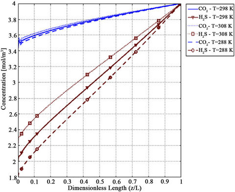
Figure 11. Effect of temperature on CO2 and H2S shell side concentration profile for VL = 1 m/s, VG = 3 m/s,  =
=  = 4 mol/m3 and T = 298 K.
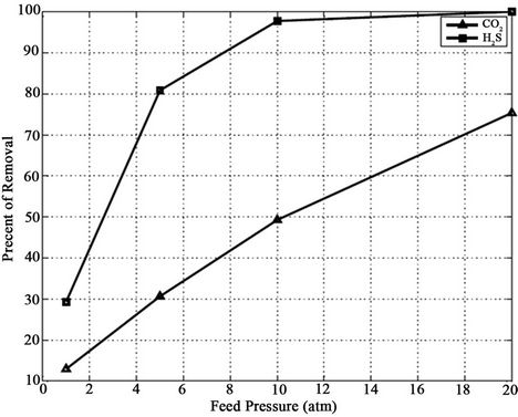
Figure 12. Effect of pressure on CO2 and H2S removal efficiencies for Methanol absorbent at VL = 0.1 m/s, VG = 3 m/s and T = 298 K.
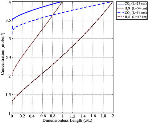
Figure 13. Effect of fiber length on CO2 and H2S concentration depletion in the gas phase along fiber length for methanol absorbent at VL = 1 m/s, VG = 3 m/s and T = 298 K.
and it might be an alternative to chemical solvents. At the module exit, complete H2S concentration depletion is relatively above 10 atm while at 1 atm this value is about 30%. High partial pressure of CO2 and H2S or application of physical solvent with high absorption power leads to lower amounts of circulation. For example, the circulation rate need to absorption of CO2 at a feed pressure of 10 atm in methanol is only about one-fourth of that circulation rate under 1 atm operating pressure.
Note that because the model results are based on “nonwetted mode” in which the gas mixture filled the membrane pores and assuming complete non-wetting conditions is valid at low pressure operations, it is expected that model overestimates CO2 removal efficiency at high pressure. This can be attributed to mass transfer resistance caused by partial wetting of pores in hollow fiber membrane [5].
The membrane length needed to achieve the desired removal efficiency is a significant parameter. By increasing the membrane length, the membrane area for mass transfer increased and thus, higher removal efficiency is achieved. As shown in Figure 13, we examined this effect for two membrane length, i.e. 27 cm and 54 cm. As a result of doubling the length, CO2 removal efficiency increased by 60% and H2S removal efficiency by 40% for VL = 1 m/s, VG = 3 m/s,  =
=  = 4 mol/m3 and T = 298 K.
4. Conclusions
The physical absorption of CO2 and H2S from CO2/H2S/ CH4 mixture (when the partial pressure of components is 10% of total pressure) was simulated. The effect of liquid velocity, gas velocity, temperature and pressure on removal efficiency was explored and the concentration distributions inside the shell, through the membrane, and within the tube side were studied. The results indicate that methanol has the potential as a low-cost, green physical solvent for CO2 capture in HFMGA. Relative absorption rate of CO2 using methanol absorbent is in the range 1.5 to 2.7 and relative absorption rate of H2S using methanol absorbent is in the range 2.9 to 3.75 in comparison with the case of water absorbent for given operating conditions (VG = 2 m/s,  =
=  = 4 mol/m3, T = 298 K). However, in simultaneously absorption of CO2 and H2S using methanol in MGA selectivity remains relatively constant with increasing the methanol absorbent flow rate. With increasing the temperature, the removal efficiencies slightly decreased. At high pressures, methanol as a physical solvent is more efficient and it might be an alternative to chemical solvents. Moreover, CO2 removal efficiency about 60% and H2S removal efficiency about 40% increased as a result of doubling the membrane length.
5. Commemoration
The authors are particularly grateful to Prof. Mohammad Khoshnoodi from University of Sistan and Baluchestan, the project manager who passed away unexpectedly, for his suggestions and knowledge shared.
REFERENCES
- R. Faiz and M. Al-Marzouqi, “Mathematical Modeling for the Simultaneous Absorption of CO2 and H2S Using MEA in Hollow Fiber Membrane Contactors,” Journal of Membrane Science, Vol. 342, No. 1-2, 2009, pp. 269-278. doi:10.1016/j.memsci.2009.06.050
- R. N. Maddox, “Gas Conditioning and Processing,” Campbell Petroleum Series, 3rd Edition, Vol. 4, 1982.
- L. Sumin, et al., “The Enhancement of CO2 Chemical Absorption by K2CO3 Aqueous Solution in the Presence of Activated Carbon Particles,” Chinese Journal of Chemical Engineering, Vol. 15, No. 6, 2007, pp. 842-846. doi:10.1016/S1004-9541(08)60012-9
- A. Mandowara and P. K. Bhattacharya, “Membrane Contactor as Degasser Operated under Vacuum for Ammonia Removal from Water: A Numerical Simulation of Mass Transfer under Laminar Flow Conditions,” Computers and Chemical Engineering, Vol. 33, No. 6, 2009. pp. 1123-1131. doi:10.1016/j.compchemeng.2008.12.005
- A. Gabelman and S. T. Hwang, “Hollow Fiber Membrane Contactors,” Journal of Membrane Science, Vol. 159, No. 1-2, 1999, pp. 61-106. doi:10.1016/S0376-7388(99)00040-X
- V. Y. Dindore, D. W. F. Brilman and G. F. Versteeg, “Modelling of Cross-Flow Membrane Contactors: Mass Transfer with Chemical Reactions,” Journal of Membrane Science, Vol. 225, No. 1-2, 2005, pp. 275-289. doi:10.1016/j.memsci.2005.01.042
- H. Jeon, et al., “Absorption of Sulfur Dioxide by Porous Hydrophobic Membrane Contactor,” Desalination, Vol. 234, No. 1-3, 2008, pp. 252-260. doi:10.1016/j.desal.2007.09.092
- K. A. Hoff, et al., “Modeling and Experimental Study of Carbon Dioxide Absorption in Aqueous Alkanolamine Solutions Using a Membrane Contactor,” Industrial & Engineering Chemistry Research, Vol. 43, No. 16, 2004, pp. 4908-4921. doi:10.1021/ie034325a
- A. Kohl and R. Nielsen, “Gas Purification,” 5th Edition, Gulf Publishing Company, Houston, 1997.
- G. Hochgesand, “Rectisol and Purisol,” European and Japanese Chemical Industrials Symposium, 1970, Vol. 62, No. 7, pp. 37-43.
- J. A. Delgado, et al., “Simulation of CO2 Absorption into Aqueous DEA Using a Hollow Fiber Membrane Contactor: Evaluation of Contactor Performance,” Chemical Engineering Journal, Vol. 62, 2009, pp. 396-405. doi:10.1016/j.cej.2009.04.064
- R. Wang, D. F. Li and D. T. Liang, “Modeling of CO2 Capture by Three Typical Amine Solutions in Hollow Fiber Membrane Contactors,” Chemical Engineering and Processing, Vol. 43, No. 7, 2004, pp. 849-856. doi:10.1016/S0255-2701(03)00105-3
- W. Rongwong, R. Jiraratananon and S. Atchariyawut, “Experimental Study on Membrane Wetting In Gas-Liquid Membrane Contacting Process for CO2 Absorption by Single and Mixed Absorbents,” Separation and Purification Technology, Vol. 69, 2009, pp. 118-125. doi:10.1016/j.seppur.2009.07.009
- D. Wang, W. K. Teo and K. Li, “Removal of H2S to Ultra-Low Concentrations Using an Asymmetric Hollow Fibre Membrane Module,” Separation and Purification Technology, Vol. 27, No. 1, 2002, pp. 33-40. doi:10.1016/S1383-5866(01)00186-1
- P. Keshavarz, J. Fathhikalajahi and S. Ayatollahi, “Mathematical Modeling of the Simultaneous Absorption of Carbon Dioxide and Hydrogen Sulfide in a Hollow Fiber Membrane Contactor,” Separation and Purification Technology, Vol. 63, No. 1, 2008, pp. 145-155. doi:10.1016/j.seppur.2008.04.008
- S. Wang, K. Hawboldt and M. A. Abdi, “Novel DualMembrane Gas-Liquid Contactors: Modelling and Concept Analysis,” Industrial & Engineering Chemistry Research, Vol. 45, No. 23, 2006, pp. 7882-7891. doi:10.1021/ie051368d
- A. Mansourizadeh, A. F. Ismail and T. Matsuura, “Effect of Operating Conditions on the Physical and Chemical CO2 Absorption through the PVDF Hollow Fiber Membrane Contactor,” Journal of Membrane Science, Vol. 353, No. 1-2, 2010, pp. 192-200. doi:10.1016/j.memsci.2010.02.054
- R. Faiz and M. Al-Marzouqi, “CO2 Removal from Natural Gas at High Pressure Using Membrane Contactors: Model Validation and Membrane Parametric Studies,” Journal of Membrane Science, Vol. 365, No. 1-2, 2010, pp. 232-241. doi:10.1016/j.memsci.2010.09.004
- J. Happel, “Viscous Flowrelative to Arrays of Cylinders,” AIChE Journal, Vol. 5, No. 2, 1959, pp. 174-177. doi:10.1002/aic.690050211
- M. Al-Marzouqi, et al., “Modeling of CO2 Absorption in Membrane Contactors,” Separation and Purification Technology, Vol. 59, No. 1, 2008, pp. 286-293.
- M. Mavroudi, S. P. Kaldis and G. P. Sakellaropoulos, “Reduction of CO2 Emissions by a Membrane Contacting Process,” Fuel, Vol. 82, No. 15-17, 2003, pp. 2153-2159. doi:10.1016/S0016-2361(03)00154-6
- P. Keshavarz, J. Fathhikalajahi and S. Ayatollahi, “Analysis of CO2 Separation and Simulation of a Partially Wet-Ted Hollow Fiber Membrane Contactor,” Journal of Hazardous Materials, Vol. 152, No. 3, 2008, pp. 1237- 1247. doi:10.1016/j.jhazmat.2007.07.115
- G. F. Versteeg and W. P. M. Van Swaaij, “On the Kinetics between CO2 and Alkanolamines both in Aqueous and Non-Aqueous Solutions I. Primary Andsecondary Amines,” Chemical Engineering Science, Vol. 43, No. 3, 1988, pp. 573-585. doi:10.1016/0009-2509(88)87017-9
- J. J. Carroll and A. E. Mather, “The Solubility of HydroGen Sulphide in Water from 0˚C to 90˚C and Pressure to 1 MPa,” Geochimica et Cosmochimica Acta, Vol. 53, No. 6, 1989, pp. 1163-1170. doi:10.1016/0016-7037(89)90053-7
- K. Lunsford and G. Mcintyre, “Decreasing Contactor Temperature Could Increase Performance,” GPA Annual Convention, Bryan Research and Engineering, Inc., Texas, 1999, pp. 121-127.
- E. L. Cussler, “Diffusion Mass Transfer in Fluid Systems,” Cambridge University, Cambridge, 1984.
- M. V. Diaz and A. Coca J., “Correlation for the Estimation of Gas-Liquid Diffusivity,” Chemical Engineering Communications, Vol. 52, No. 4-6, 1987, pp. 271-281. doi:10.1080/00986448708911872
- R. H. Perry, “Perry’s Chemical Engineers’ Handbook,” 7th Edition, McGraw-Hill, New York, 1997.
- B. E. Poling, J. M. Prausnitz and J. P. O’Connell, “The Properties of Gases and Liquids,” 5th Edition, McGrawHill, New York, 2004.
- R. Faiz and M. Al-Marzouqi, “H2S Absorption via CarBonate Solution in Membrane Contactors: Effect of Species,” Journal of Membrane Science, Vol. 350, No. 1-2, 2010, pp. 200-210. doi:10.1016/j.memsci.2009.12.028
- V. Y. Dindore, D. W. F. Brilman and G. F. Versteeg, “Hollow Fiber Membrane Contactor as a Gas-Liquid Model Contactor,” Chemical Engineering Science, Vol. 60, No. 2, 2005, pp. 467-479. doi:10.1016/j.ces.2004.07.129
Nomenclature
NOTES
*Corresponding author.