Journal of Signal and Information Processing
Vol. 4 No. 3 (2013) , Article ID: 35864 , 11 pages DOI:10.4236/jsip.2013.43037
Track-to-Track Association Technique in Radar Network in the Presence of Systematic Errors
![]()
Research Institute of Information Fusion, Naval Aeronautical Engineering Institute, Yantai, China.
Email: *yangjian2575@163.com
Copyright © 2013 Jian Yang et al. This is an open access article distributed under the Creative Commons Attribution License, which permits unrestricted use, distribution, and reproduction in any medium, provided the original work is properly cited.
Received May 12th, 2013; revised June 12th, 2013; accepted July 12th, 2013
Keywords: Systematic Errors; Phase Correlation; Track-to-Track Association; Sensor Registration; Radar Network
ABSTRACT
The presence of systematic measuring errors complicates track-to-track association, spatially separates the tracks that correspond to the same true target, and seriously decline the performances of traditional track-to-track association algorithms. Consequently, the influence of radar systematic errors on tracks from different radars, which is described as some rotation and translation, has been analyzed theoretically in this paper. In addition, a novel approach named alignment-correlation method is developed to estimate and reduce this effect, align and correlate tracks accurately without prior registration using phase correlation technique and statistic binary track correlation algorithm. Monte-Carlo simulation results illustrate that the proposed algorithm has good performance in solving the track-to-track association problem with systematic errors in radar network and could provide effective and reliable associated tracks for the next step of registration.
1. Introduction
Radar network data processing technology is an effective method to counterwork the so-called “four threats”, i.e. stealth, jamming, low altitude invasion and anti-radiation missile in the modern war [1], which can achieve an optimization performance of target detection, tracking and information fusion by properly locating multiple radars and sharing, synthesizing, mastering and managing of the radar network measuring information.
Specifically, the main function of the radar network data processing system is to perform radar registration, track-to-track association and track fusion [2]. And the registration and track-to-track association are the crucial sectors in a radar network data processing system [3,4]. The technique of registration, with the purpose of exactly estimating the sensor systematic errors and aligning the target tracks that correspond to the same true target, is the necessary precondition of the next accurate track-to-track association. And the track-to-track association technique, i.e. track correlation, whose purpose is to accurately associate the target tracks provided by the networked radars, is a basis for the next track fusion processing [5]. However, the precondition of exact registration is that the tracks must have been accurately associated. Thus, an intractable contradiction between track-to-track association and registration appears, that is accurate track-totrack association and needs exact registration, namely the estimate of the systematic errors, and the exact registration process depends on accurate association (i.e. correlation) of target tracks.
Many algorithms have been proposed to solve the track-to-track association problem, such as Singer’s algorithm [6,7], Bar-Shalom’s algorithm [8,9], Sequential Algorithm [10,11], assignment algorithm [12], likelihood ratio test algorithm [13], multiple hypothesis test algorithm [14], and so on. The current track-to-track association algorithms have good performance in the ideal simulation environments, but when using in practical application it is often encountered that the probability of track correct correlation seriously falls and the probability of track false correlation and missing correlation greatly rise. It is mainly because that the existence of measuring and locating systematic errors in radar network are often neglected in the current track-to-track association algorithms. However, the accurate track-to-track association is the precondition of the registration, and inevitably, the registration based on the false associated targets can not estimate the systematic errors correctly and at last the estimated result will lead to the invalidation of all targets’ track-to-track association and fusion. In addition, the registration algorithms [15-20] often neglect this problem and suppose that the correct associated tracks of targets have been acquired (i.e. the tracks used for registration corresponding to the same target), but in practice, the target tracks are not likely to be accurately associated because of the systematic errors. Then large errors would be produced in the estimation of systematic errors using the unreliable associated tracks.
So it is necessary to research new techniques to solve the ambivalent problem. The first way is to present new registration technique which does not need the accurately associated tracks [21,22]. The second is to introduce new track-to-track association technique which does not need exact registration of radar systematic errors. And the latter one which is called track alignment-correlation technique here is the contribution of this paper (while the current track-to-track association algorithms are called traditional algorithms in this paper), which can be subdivided into two stages, namely track alignment and track correlation. Different from the traditional track-to-track association techniques, the track alignment-correlation technique only provides accurately associated track data for registration.
This paper is organized as follows. The influence on the target tracks caused by the systematic errors in radar network is analyzed in Section 2, which mainly describes the influence as some rotation and mass motion of tracks between radars. In Section 3, a track alignment-correlation algorithm based on 1D and 2D phase correlation technique is presented. In the stage of track alignment, the proposed algorithm describes the tracks reported by the network radars respectively as a whole data in a track data space, and estimates the rotation and the translation between the whole tracks data from the network radars using Radon transform and Fourier transform [23,24], then aligns and compensates the reported tracks data of targets in the common Cartesian coordinate system. After that, a statistical binary track correlation algorithm is used to correlate the aligned tracks in the stage of track correlation. Section 4 presents the simulation results to demonstrate that the proposed algorithm can align and correlate the tracks accurately without estimation and compensation the radar systematic errors. Conclusions are given in Section 5.
2. Influence Analysis of the Radar Systematic Errors on Target Tracks
Consider the situation that there are two 2D radars (radar A and radar B) in a radar network as illustrated in Figure 1. Radar A is set as the fusion center, which is located at the origin of the common Cartesian coordinate system.
The coordinates of radar B is . Let
. Let
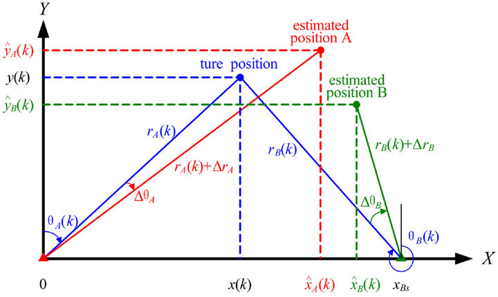
Figure 1. The geometry of radar and target.
 denote the true position of target at time k in Cartesian coordinate system, while
  and
and  correspond to the estimated positions of the same target provided by radar A and radar B respectively. The true polar coordinates of the target are denoted by
  and
and , while the range and azimuth systematic errors of these two radars are
  and
and .
.
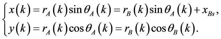
Suppose that the filtering random error can be ignored, and then the position state estimate of each radar can be expressed as
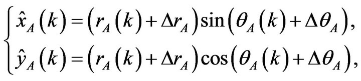 (1)
(1)
and
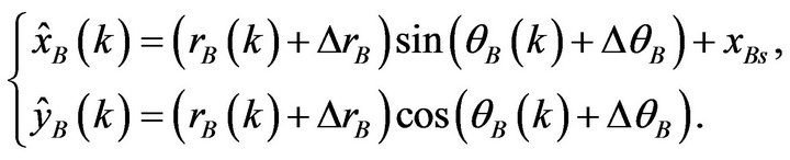 (2)
(2)
The above can be rewritten in a compact form as
 (3)
(3)
and
 (4)
(4)
As shown in Figure 1, the relationship between
 and
and  can be derived as
 (5)
(5)
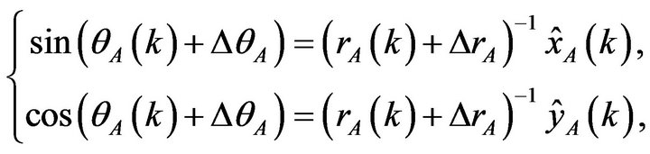
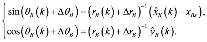
Then using some expansion and substitution, (2) can be rewritten as
 (6)
(6)
Substituting (3) and (4) into (6), it can be expressed as
 (7)
(7)
Then
 (8)
(8)
Note that, generally,  and
and that is
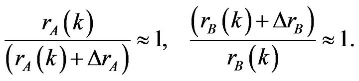 (9)
(9)
Define
 (11)
(11)
and
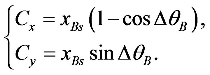 (12)
(12)
Generally, it can be assumed that the azimuth systematic errors ![]() and
and ![]() can be seen as constants approximatively during the short duration of radar observation. Therefore,
can be seen as constants approximatively during the short duration of radar observation. Therefore,  and
and  in Equations
(11) and (12) are almost constants.
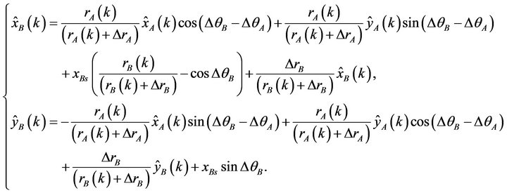
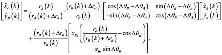
Substituting (11) and (12) into (10), it becomes
 (13)
(13)
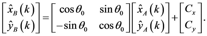
Then from (11)-(13), it is not difficult to get the conclusion that the influence of the radar systematic errors is to induce some translation and rotation between the tracks corresponding to the same target. Ideally, the target tracks provided by radar B would coincide with the track provided by radar A after rotating  and translating
 .
.
Thus, the next work is to estimate the rotation of 
and the translation of , then the target tracks provided by different radars could be aligned and compensated in the common Cartesian coordinate system. After that, the corresponding track correlation algorithm can be adopted to associate the tracks.
3. The Track Alignment-Correlation Technique Based on Phase Correlation
3.1. Description of the Track Data Space
The coordinates of the target tracks provided by two radars are transformed into the common Cartesian coordinate system. Then a reliable rectangle area is selected for track alignment from common surveillance area. Suppose that the center coordinates of the selected rectangle area is  and the width and height of the area are a and b respectively. Then the four endpoints of the selected rectangle area for track alignment are described by
 ,
, ,
,
 and
and  respectively.
Then, the track alignment area is divided into 
grids. In this way,  matrices
  and
and  named track data space matrix for radar A and radar B can be constructed, in which the track plot according to the grid where the track plot falls can be labeled. Define
 as the grid index, then the matrices
  and
and  of track data space can be defined respectively as (see Equation (14))
where C is a constant.
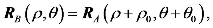
Thus, equation (13) can be transformed as
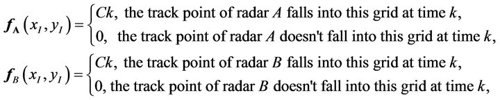 (14)
(14)
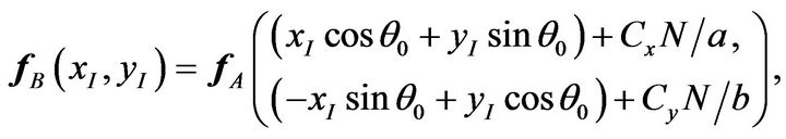 (15)
(15)
which means that the data space  can be derived from
  by rotating
  and translating
 respectively in direction of
  and
and .
.
3.2. Track Alignment
3.2.1. Radon Transform
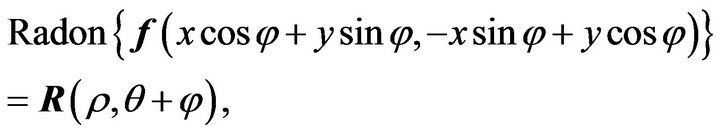
As well known, the Radon transform of 2D data space
 is the curvilinear integral of the data space along a group of lines in the plane where the function exists [23], and the exact definition is
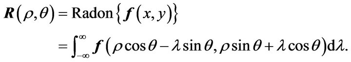 (16)
(16)
Furthermore, the Radon transform has characteristics about translation and rotation as follows:
1) Characteristic about Translation The translation in the data space can be expressed as that  has different translocations in the
  direction corresponding to different
  in the Radon transform domain, namely
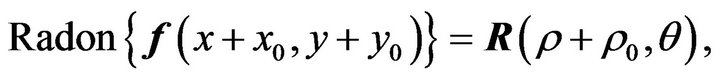 (17)
(17)
where .
.
2) Characteristic about Rotation The rotation in the data space can be described as that  has some translocations in the
  direction, namely
 (18)
(18)
where ![]() is the rotation angle.
is the rotation angle.
3.2.2. Estimation of the Rotation Angle
According to the characteristics of Radon transform, suppose the Radon transform of track data space
 and
and  are
are  and
and
 respectively. Due to the rotation of
  and translation of
  between
  and
and , and by applying the Radon transform respectively to both sides of Equation (15), the relationship between
  and
and  can be described as
 (19)
(19)
where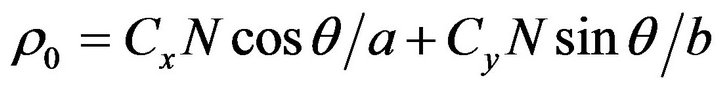 .
.
Using different value of , 1D Fourier transform is applied to both sides of equation (19) in the
  direction, and the equation in frequency domain can be obtained as
 (20)
(20)
where  and
and  represent the 1D Fourier transform of
  and
and  respectively. By getting the magnitude of both sides of equation (20), the amplitude spectrum relationship can be obtained as
 (21)
(21)
Suppose that the magnitude of  and
and
 are denoted as
  and
and 
respectively, then the above equation is rewritten as
 (22)
(22)
Thus, it is not difficult to find that the rotation between the track data spaces  and
and  is totally transformed into the translation of amplitude spectrum in the
  direction.
For each![]() , applying 1D Fourier transform to both sides of equation (22) in the
, applying 1D Fourier transform to both sides of equation (22) in the  direction, and we get
 (23)
(23)
where  and
and  denote the 1D Fourier transform of
  and
and  in the
direction.
Equation (23) illustrates that  and
and
 have the same magnitude in frequency domain whatever
 ![]() takes, but have a phase difference, which equals to the phase of cross power spectrum between
takes, but have a phase difference, which equals to the phase of cross power spectrum between  and
and  in the
  directionand can be expressed as
 (24)
(24)
where  is the complex conjugate of
 .
.
Thus, for all![]() , by applying inverse Fourier transform to Equation (24) in the
, by applying inverse Fourier transform to Equation (24) in the ![]() direction, a series of unit impulse functions are formed in the
direction, a series of unit impulse functions are formed in the ![]() direction. The location of the peak point of the impulse is
direction. The location of the peak point of the impulse is .
.
Obviously,  is the rotation angle between two data space, namely the relative rotation angle between the tracks provided by the two radars.
Specifically, the translation of  in the
  direction, i.e. the rotation of
  in the track data space, can be extracted by the following formula
 (25)
(25)
where  means the operator of 1D inverse Fourier transform in the
 ![]() direction.
direction.
After obtaining the rotation of , the data space
  can be obtained by rotating the data space
  through
 ,
,
 (26)
(26)
Thus, after the transformation, there is only the translation of  between
  and
and ,
,
 (27)
(27)
3.2.3. Estimation of the Translation
Similarly, applying Fourier transform to Equation (27), then
 (28)
(28)
where  denotes the corresponding Fourier transform of
 .
.
The above equation illustrates that the data space
 and
and  have the same magnitude in the frequency domain, but also have a phase difference, which equals to the phase of cross power spectrum between the two data space, expressed as
 (29)
(29)
where  is the complex conjugate of
 .
.
Similarly, by applying inverse Fourier transform to Equation (29), a unit impulse function is formed, whose peak point locates at , which is the relative translation between the two data space.
The translation of  between data spaces can be obtained by searching for the coordinates of the peak point. Specifically,
  can be extracted by the following formula
 (30)
(30)
where  is the 2D inverse Fourier transform operator.
Since N, a and b are known variants, it is not difficult to obtain the translation of  from
from
 . Then according to
  and
and
 , compensate the target measurements gotten from radar A, and the tracks reported by different radars can be well aligned together in the common coordinates.
3.3. Track Correlation
3.3.1. Binary Rules
There is a double threshold detection [25] signal processing method in the automatic radar detection theory. The so-called double threshold in signal processing detection can be mainly divided into two steps.
The first step is to compare R observed impulse samples with a fixed threshold (viz. the threshold 1) one by one, and count the total number of the samples which exceeds the threshold 1 using a counter.
Then, the second step is to compare the final counting value of counter with another fixed threshold (viz. the threshold 2, usually a integer L, and ). When the final counting value exceeds or equals to L, the signal is regarded as existence.
Based on the main idea of the double threshold detection method, an algorithm named statistic binary track correlation is proposed in [26].
The sets of track number initialized by radar A and B are defined as
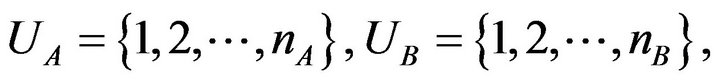 (31)
(31)
where  and
and  are the number of the tracks reported by each radar respectively.
Let  and
and ,
,  denote the state of target i estimated by radar A and target j estimated by radar B respectively, namely corresponding to the ith and jth tracks reported by radar A and B. And the state estimation can be expressed respectively as
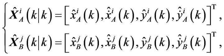 (32)
(32)
where  and
and  mean the position in the x and y direction of target i estimated from radar A and target j estimated from radar B respectively.
 and
and  mean the velocity in the x and y direction of target i estimated from radar A and target j estimated from radar B respectively. The suprescript “T” denotes matrix transpose.
The track correlation process can be described as a hypothesis-testing problem as Equation (33).
Using the test variable of Singer’s algorithm [6,7], the test statistics of the binary track correlation algorithm should be calculated point by point as Equation (34).
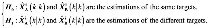 (33)
(33)
 (34)
(34)
 (35)
(35)
where  and
and  are the error covariance of the state estimation of the track i from radar A and the track j from radar B respectively, and
  denotes the correlation mass that track i from radar A correlated with track j from radar B till time k.
The first threshold can be set as
 (36)
(36)
where ![]() is the significance level, and can be set as
is the significance level, and can be set as . Then the test of H0 vs. H1 is as follow
 (37)
(37)
However, H0 may not be accepted if
 for that there may be more than one track will be correlated with track i. This problem, namely multivalency processing problem, is discussed in Section 3.3.3.
3.3.2. Track Mass Designing
Two kinds of track mass are designed here. One is the track correlation mass and another is the track separation mass. As said above, the track correlation mass
 denotes the times of track i from radar A correlated with track j from radar B till time k. And the separation mass of track i and j is defined as
 (38)
(38)
From equation (38) it can be seen that if
 (39)
(39)
the correlation test would not be performed between track i and j at time k. Since  (track i and j are uncorrelated) must be in existence if
at time . Similarly, the correlation between track i
and j will be confirmed if
 (40)
(40)
The correlation test between track i and j would be cease at time k if only one track (j) can satisfy (40), then track i and j would be regarded as the correlated track and performed no correlation test any more. However, if there are more than one track j can satisfy Equation (40), the correlation test should be performed till  to give a precise correlation mass for the multivalency processing latter. On the other hand, the track i with no other track correlated till
  will be performed test in the next cycle.
3.3.3. Multivalency Processing Method
There are two cases in which multivalency processing method is applied, one of them is  and the other is
 .
.
In case one, there are more than one track j satisfy the condition of , thus, in this case, track j*
which maximize the track correlation mass  will be correlated with track i.
 (41)
(41)
where  is the set of track j correlated with track i on the condition of
 .
.
When there are more than one track can maximize the track correlation mass , the track
  will be accepted if
 (42)
(42)
In case two, the correlation test will be ceased if (39) is satisfied. Otherwise, a temporary system track will be set. Corresponding to a given track i, the track j* will be accepted when .
.
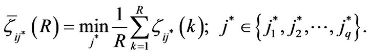
If there are more than one track j* accepted by the multivalency processing method, the track j* which will satisfy the condition  can be correlated with track i.
However, if there are more than one track can correlated with track i, the track jp will be accepted when
 (43)
(43)
where  is the position differences between track i and j at time q, and
  is the set of track which can satisfy
 .
.
Once track j is correlated with track i, the correlation test would not be performed to track i or j at time k.
4. Simulation and Analysis
After the text edit has been completed, the paper is ready for the template. Duplicate the template file by using the Save As command, and use the naming convention prescribed by your journal for the name of your paper. In this newly created file, highlight all of the contents and import your prepared text file. You are now ready to style your paper.
Monte-Carlo simulations are carried out to demonstrate the validation of the proposed alignment-correlation algorithm in the existence of systematic error in this paper.
Consider a surveillance network with 2 radars, whose coordinates are (0, 0) and (150 km, 0) respectively. The standard variances of the measurement noise are 60 m and 0.4˚ for range and azimuth measurements. The detection range of two radars are 140 km. Suppose that the targets do linear motion with speed dynamic noises in a 2D space whose initial speed and heading are uniformly distributed among 100 ~ 150 m/s and 0 ~ 2p rad respectively. The initial positions of targets are generated according to the uniform distribution in a rectangle area, whose endpoints are set at (65 km, 65 km), (65 km, 85 km), (85 km, 85 km) and (85 km, 65 km) respectively. The rectangle area, whose endpoints are set at (55 km, 55 km), (55 km, 95 km), (95 km, 95 km) and (95 km, 55 km) is selected as the alignment-correlation area.
The runs of Monte-Carlo simulation is 100 and the simulation time of each run is 100 s. The simulation is done in the following four environments:
Environment 1: the targets number appearing in the common surveillance area is set as 15 and the systematic errors of the two radars are 0.5 km and 0.5 km in the range direction, 0.5˚ and −0.5˚ in the azimuth direction respectively.
Environment 2: the targets number appearing in the common surveillance area is set as 30 and the systematic errors of the two radars are 0.5 km and 0.5 km in the range direction, 0.5˚ and −0.5˚ in the azimuth direction respectively.
Environment 3: the targets number appearing in the common surveillance area is set as 15 and the systematic errors of the two radars are 1 km and 1 km in the range direction, 1˚ and −1˚ in the azimuth direction respectively.
Environment 4: the targets number appearing in the common surveillance area is set as 30 and the systematic errors of the two radars are 1 km and 1 km in the range direction, 1˚ and −1˚ in the azimuth direction respectively.
The performance of the traditional track-to-track association technique is often evaluated by three kinds of probabilities, namely the correct correlation probability , the false correlation probability
  and the miss correlation probability
 . While, different from the purpose of the traditional track-to-track association technique, the purpose of the proposed alignment-correlation technique in this paper is to provide reliable couples of tracks for registration but not track fusion, so do not emphasis on associating all tracks. Thus, a good performance of the alignment-correlation technique requires the false correlation probability as low as possible, and the correct correlation probability as high as possible among the associated couples of tracks. As to the miss correlation probability, alignment-correlation technique only requires that it should satisfy that most of the target tracks are associated effectively.
Based on the above analysis, in order to describe the requirement better, the above probabilities should be redefined. Suppose that the number of the correct, false and miss associated tracks in the result are ,
,  and
and  respectively, then the correct correlation probability
 , the false correlation probability
  and the miss correlation probability
  are redefined as
 ,
,  and
and
 respectively.
  and
and 
can reflect the capability of effective correlation, and
 .
.
The simulation results are showed in the following figures and table. The tracks before alignment in four environments are shown in Figures 2, 4, 6 and 8, and the tracks after alignment in four environments are displayed in Figures 3, 5, 7 and 9. According to the new definitions, the performance of correct, false and miss correlation probability using traditional track-to-track association algorithm in [10] and the track alignment-correlation algorithm in each environment are given in Table 1 through 100 Monte-Carlo simulations (The L/R logic selects 6/8).
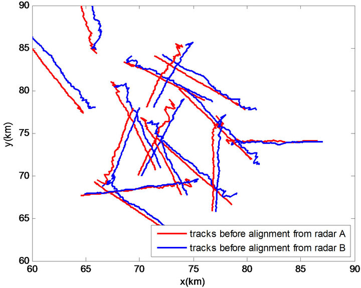
Figure 2. Tracks before alignment in Environment 1.
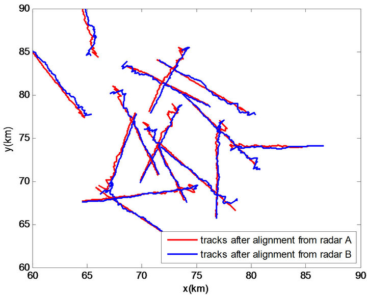
Figure 3. Tracks after alignment in Environment 1.
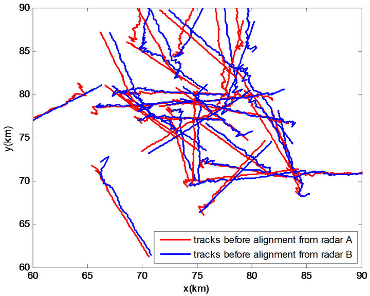
Figure 4. Tracks before alignment in Environment 2.
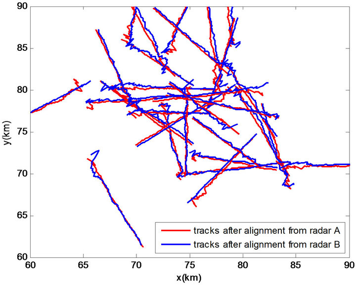
Figure 5. Tracks after alignment in Environment 2.
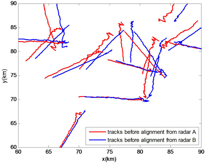
Figure 6. Tracks before alignment in Environment 3.
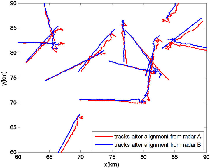
Figure 7. Tracks after alignment in Environment 3.
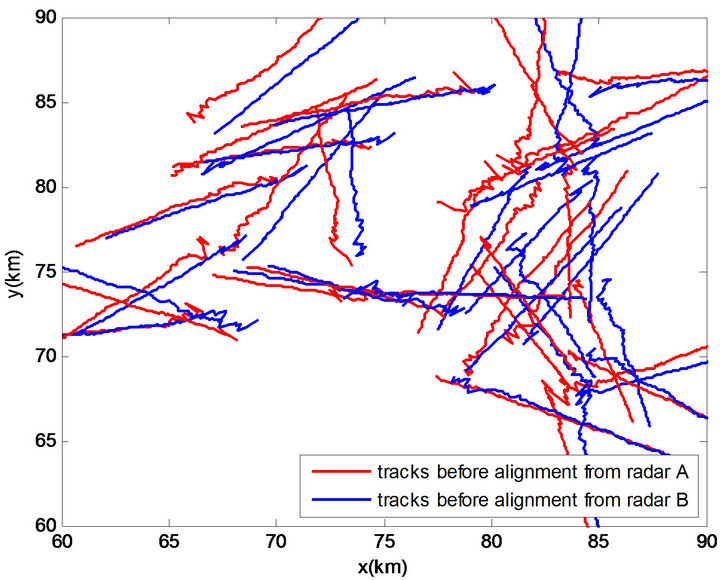
Figure 8. Tracks before alignment in Environment 4.
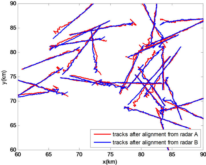
Figure 9. Tracks after alignment in Environment 4.
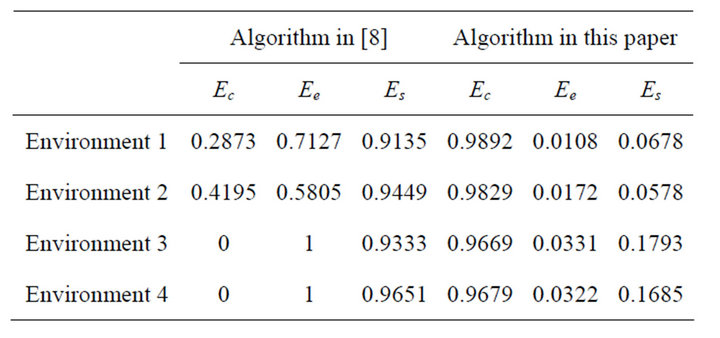
Table 1. Probability of track-to-track association.
From Figures 2, 4, 6 and 8, it can be seen that, without estimating and compensating the existing systematic error, the tracks reported by two radars are seriously deviated. When employing only traditional track-to-track association technique which is mainly based on the statistic distance between track plots without considering the systematic errors, it is natural that the deviated tracks can not be associated effectively and exactly. The results can be seen from Table 1 that more than 90% of the target tracks haven’t been associated without regard to right or wrong, and in the associated tracks, most of them are false associated tracks in the relative little errors environment (viz. Environment 1 and 2), and even all of associated tracks are false associated in the larger errors environment (viz. Environment 3 and 4). So absolutely, it can not provide reliable couples of tracks for the registration using the traditional algorithm.
From Figures 3, 5, 7 and 9, it can be seen that the target tracks have been exactly aligned together by using the proposed algorithm. It can be seen in Table 1 that the proposed algorithm has good performance on the correlation-alignment of tracks, specifically, the correct correlation probabilities of the tracks are all above 96%, and the false correlation probabilities are all low in four simulation environments. The results mean that the proposed correlation-alignment algorithm is reliable and effective when dealing with the track-to-track association problem with the existence of systematic errors in radar network.
In the meantime, by comparing the simulation results in Environment 1, 3 with Environment 2, 4, it shows that, although the targets in the Environment 2, 4 are denser than the targets in the Environment 1, 3, the difference of target density has little influence on the simulation performance of proposed algorithm. It also reveals that the proposed algorithm has a good adaptive capability to the target density.
Similarly, the differences of the correlation performance between Environment 1, 2 and Environment 3, 4 illustrate that larger systematic errors bring in poorer performance of the proposed algorithm. It mainly because that the larger the systematic errors is, the larger the deviation of the tracks will be and the less the usable track data from the same target in the alignment-correlation area will be. This can be solved by properly augmenting the alignment-correlation area. Nevertheless, the correct correlation probabilities in Environment 3, 4 only drop less than 3% compared to the correct correlation probabilities in Environment 1, 2, and it means that the proposed algorithm has robustness to the systematic error.
Finally, it can be seen from Table 1 that the miss correlation probabilities in Environment 3, 4 increase by a certain extent compared to the miss correlation probabilities in Environment 1, 2. It reflects that the miss correlation probability can be influenced by systematic errors, but even so the miss correlation probabilities in Table 1 reveal that the alignment-correlation algorithm can still associate most of tracks even in worse situations, and the corresponding correct and false correlation probabilities show the validity of correlation performance.
5. Conclusions
This paper has researched on the track-to-track association problem with measuring systematic errors in radar network, the main contributions of this paper are:
• The influence of the radar systematic errors on target tracks has been analyzed theoretically;
• To solve the association problem, a track alignmentcorrelation algorithm has been proposed, which includes two stages of track alignment and track correlation.
In the end, Monte-Carlo simulation results show that the proposed algorithm has reliable and effective track association performance with the existence of systematic errors in radar network, moreover, it has a good adaptive capability to the target density and robustness to the systematic errors.
Overall, the proposed algorithm can provide adequate reliable associated tracks for the next step of registration. With systematic errors in the radar network, the proposed algorithm has a good capability in solving the contradiction between track traditional track-to-track association technique and registration technique.
6. Acknowledgements
This work was supported in part by National Natural Science Foundation of China (NSFC-60801049, NSFC- 61032001).
REFERENCES
- Y. He, J. Xiu, J. Zhang and X. Guan, “Radar Data Processing with Applications,” 2nd Edition, Publishing House of Electronics Industry, Beijing, 2009.
- S. S. Blackman, “Multiple-Target Tracking with Radar Applications,” Artech House, Norwood, 1986.
- B. F. La Scala and A. Farina, “Choosing a Track Association Method,” Information Fusion, Vol. 3 No. 2, 2002, pp. 119-133. doi:10.1016/S1566-2535(02)00050-7
- D. E. Maurer, “Information Handover for Track-to-Track Correlation,” Information Fusion, Vol. 4, No. 4, 2003, pp. 281-295. doi:10.1016/j.inffus.2003.03.001
- Y. He, G. Wang, D. Lu and Y. Peng, “Multisensor Information Fusion with Applications,” 2nd Edition, Publishing House of Electronics Industry, Beijing, 2007.
- R. A. Singer and A. J. Kanyuck, “Computer Control of Multiple Site Track Correlation,” Automatica, Vol. 7, No. 4, 1971, pp. 455-463. doi:10.1016/0005-1098(71)90096-3
- W. R. Ditzler, “A Demonstration of Multisensor Tracking,” Proceedings of the 1987 Tri-Service Data Fusion Symposium, JHU/APL, Laurel, 1987, pp. 303-311.
- Y. Bar-Shalom and H. Chen, “Multisensor Track-toTrack Association for Tracks with Dependent Errors,” Proceedings of the 43rd IEEE Conference on Decision and Control, Nassau, 14-17 December 2004, pp. 2674- 2679. doi:10.1109/CDC.2004.1428864
- L. M. Kaplan, Y. Bar-Shalom and W. D. Blair, “Assignment Costs for Multiple Sensor Track-to-Track Association,” IEEE Transactions on Aerospace and Electronic Systems, Vol. 44, No. 2, 2008, pp. 655-677. doi:10.1109/TAES.2008.4560213
- Y. He and J. Zhang, “New Track Correlation Algorithms in a Multisensor Data Fusion System,” IEEE Transactions on Aerospace and Electronic Systems, Vol. 42, No. 4, 2006, pp. 1359-1371. doi:10.1109/TAES.2006.314577
- Y. Bar-Shalom, “On the Sequential Track Correlation Algorithm in a Multisensor Data Fusion System,” IEEE Transactions on Aerospace and Electronic Systems, Vol. 44, No. 1, 2008, pp. 396-396. doi:10.1109/TAES.2008.4517016
- C. B. Chang and L. C. Youens, “Measurement Correlation for Multiple Sensor Tracking in a Dense Target Environment,” 20th IEEE Conference on Decision and Control Including the Symposium on Adaptive Processes, Vol. 20, 1981, pp. 830-831. doi:10.1109/CDC.1981.269332
- M. Kosoka, “A Track Correlation Algorithm for MultiSensor Intergration,” Journal of Guidance Control and Dynamics, Vol. 10, No. 2, 1987, pp. 166-171. doi:10.2514/3.20198
- R. J. Kenefic, “Local and Remote Track File Registration Using Minimum Description Length,” IEEE Transactions on Aerospace and Electronic Systems, Vol. 29, No. 3, 1993, pp. 651-655. doi:10.1109/7.220917
- Y. Zhou, L. Henry and B. Martin, “Sensor Alignment with Earth-Centered Earth-Fixed (ECEF) Coordinate System,” IEEE Transactions on Aerospace and Electronic Systems, Vol. 35, No. 2, 1993, pp. 410-417. doi:10.1109/7.766925
- X. Lin, T. Kirubarajan and Y. Bar-Shalom, “Multisensor-Multitarget Bias Estimation for Asynchronous Sensors,” Proceedings of SPIE Conference on Signal Processing, Sensor Fusion, and Target Recognition XIII, Vol. 5429, 2004, pp. 105-116. doi:10.1117/12.542272
- X. Lin, Y. Bar-Shalom and T. Kirubarajan, “Multisensor-Multitarget Bias Estimation for General Asynchronous Sensors,” IEEE Transactions on Aerospace and Electronic Systems, Vol. 41, No. 3, 2005, pp. 899-921. doi:10.1109/TAES.2005.1541438
- W. Li and H. Leung, “Simultaneous Registration and Fusion of Multiple Dissimilar Sensors for Cooperative Driving,” IEEE Transactions on Intelligent Transportation Systems, Vol. 5, No. 2, 2004, pp. 84-98. doi:10.1109/TITS.2004.828169
- Y. Dong, “Study on Sensor Registration for Radar Networking,” Ph.D. Thesis, Naval Aeronautical and Astronautical University, Yantai, 2007.
- K. A. Kramer and S. C. Stubberud, “Target Registration Correction Using the Neural Extended Kalman Filter,” IEEE Transactions on Instrumentation and Measurement, Vol. 59, No. 7, 2010, pp. 1964-1971. doi:10.1109/TIM.2009.2030870
- X. Lin, T. Kirubarajan and Y. Bar-Shalom, “Multisensor Bias Estimation Using Local Tracks without a Priori Association,” Proceedings of SPIE Conference on Signal and Data Processing of Small Targets, Vol. 5204, 2003, pp. 334-345. doi:10.1117/12.503715
- S. Musick and K. Kastella, “Track and Bias Estimation without Data Association,” Proceedings of SPIE in Signal Processing, Sensor Fusion, and Target Recognition IX, Vol. 4052, 2000, pp. 258-269. doi:10.1117/12.395091
- S. R. Deans, “The Radon Transform and Some of Its Applications,” John Wiley & Sons Ltd., New York, 1983.
- Q. Chen and M. Defrise, “Symmetric Phase-Only Matched Filtering of Fourier-Mellin Transforms for Image Registration and Recognition,” IEEE Transactions on Pattern Analysis and Machine Intelligence, Vol. 16, No. 12, 1994, pp. 1156-1168. doi:10.1109/34.387491
- N. Levanon, “Radar Principle,” John Wiley & Sons Ltd., New York, 1988.
- Y. He, Y. Peng, D. Lu and Z. Gao, “Binary Track Correlation Algorithms in a Distributed Multisensor Data Fusion System,” Journal of Electronics, Vol. 19, No. 6, 1997, pp. 721-728.
NOTES
*Corresponding author.