Journal of Power and Energy Engineering
Vol.04 No.04(2016), Article ID:66202,11 pages
10.4236/jpee.2016.44007
Improvement of Power System Performance Using Fuzzy Logic Based Interline Power Flow Controller [IPFC]
S. N. Dhurvey, V. K. Chandrakar
Department of Electrical Engg, G.H. Raisoni College of Engineering, Nagpur, India

Copyright © 2016 by authors and Scientific Research Publishing Inc.
This work is licensed under the Creative Commons Attribution International License (CC BY).
http://creativecommons.org/licenses/by/4.0/


Received 27 February 2016; accepted 26 April 2016; published 29 April 2016
ABSTRACT
In this paper, the nonlinear dynamic model of a multi machine power system incorporated with Interline Power Flow Controller [IPFC] has been developed for improvement in damping of power system oscillations and transient stability. The IPFC performance is tested with PI controllers in comparison with fuzzy logic based controller under healthy and abnormal operating conditions. The IPFC fuzzy controller is design to coordinate two control inputs: change in voltage and change in capacitor voltage to improve the transient stability of the multimachine system. The Interline Power Flow Controller [IPFC] with fuzzy logic controller is designed with simple fuzzy rules to coordinate the additional damping signal. The proposed controller for IPFC is able to achieve improved designed performance of the power system. Digital simulations are carried out in MATLAB environment.
Keywords:
FACTS, IPFC, Fuzzy Logic, Damping of Oscillations

1. Introduction
In a modern integrated power system, stability is of increasing importance for secure operation of large and complex systems. The high current semiconductor device based FACTS devices with proper control strategy can improve the transient stability of multimachine system. Many researchers present work on various nonlinear VSC based FACTS devices for stability improvement of the power system under various system conditions. Among these, the Unified Power Flow Controller (UPFC) is the most versatile FACTS device for improvement of transient stability and damping of oscillations [1] - [3] . Amongst the other developed VSC based nonlinear FACTS devices, Interline Power Flow Controller (IPFC) is most versatile FACTS device, it consists of number of SSSC and is connected in each line which is connected via common dc bus, solving the problem of compensating transmission lines. IPFC device performs independently controllable reactive series compensation of each individual line and also to transfer real power between the compensated lines. This capability of IPFC makes it possible to: equalize both real and reactive power flow between the lines; reduce the burden of overloaded lines by real power transfer; compensate against resistive line voltage drops and the corresponding reactive power demand and increase the effectiveness of the overall compensating system [4] - [9] .
Gomathi et al. [5] presents the state estimation of power system embedded with Interline Power Flow Controller. Jianhong Chen et al. [6] derive basic characteristics of the IPFC and two basic control systems for the IPFC to follow the reference receiving end active and reactive power inputs. Vasquez-Arnez et al. [7] present the IPFC main features and limitations while controlling the power flow. Segundo et al. [9] have examined the efficacy of VSC-based FACTS controllers for better damping performance. It is established that PI controller’s performance deteriorates under system varying conditions with nonlinear FACTS devices. Therefore, fuzzy logic based controller has advantage over the conventional controllers.
Fuzzy Logic is a form of many-valued logic. Fuzzy logic controller is robust and easily modified. It can use multiple input and output sources. Fuzzy logic has the advantage that the solution to the problem can be cast in terms that human operators can understand, which is useful for the design of the controller. Also, it does not require precise numerical values of the control inputs and the system parameters. Furthermore, it allows the knowledge from experiences to be incorporated into the control scheme by means of logical reasoning. Hence, fuzzy logic control is an ideal and suitable approach for controlling IPFC. The coordination of control signals through a conventional technique is very difficult, where as fuzzy logic control allows the knowledge from experiences to be incorporated into the control scheme by means of logical reasoning. In multi machine system, the behavior of conventional IPFC controllers is required to coordinate parameters for better performance. Chandrakar et al. [10] - [12] have analyzed the effect of coordinated fuzzy logic based UPFC, STATCOM, SSSC for improvement of transient stability of single machine infinite bus system and multi-machine test system under normal and abnormal condition. The fuzzy application is proved to be more effective control strategy over PI based controllers in nonlinear FACTS devices. Fuzzy controller with POD as additional damping controller further improves the dynamic performance of the system.
Dhurvey et al. [13] have examined the relative effectiveness of IPFC control signals on linearized power system model of single machine infinite bus system (SMIB) system for analyzing performance comparison of IPFC in coordination with Power Oscillation Damping Controller [POD] and Power System Stabilizer [PSS]. Menniti et al. [14] have discussed the structure of proposed IPFC fuzzy controller obtained on a test power system using ATP EMTP as programming environment. However, they have not applied strategy on multimachine system for analysis and POD damping signals for improved damping performance. Dash et al. [15] present a combination of both TS-fuzzy scheme and RBFN is adopted for nonlinear control of TCSC and IPFC by combining intelligent techniques. However, they have not presented independent fuzzy logic control and not included any supplementary damping signal. They have presented fuzzy interference with more complicated strategy. However, this paper delineates the simple design strategy for fuzzy logic control in comparison with PI based controller. Naresh Babu et al. [16] present the Newton-Raphson (NR) power flow solution method to study the effects of IPFC parameters for steady state analysis. N. Yadaiah et al. [17] present the survey of various techniques for linearisation of multi-machine power system dynamics and designing of controllers for the transient stability problem. Mansour-Khalilian et al. [18] designed a fuzzy logic controller to use the DSSC for enhancing transient stability in a two-machine, two-area power system. Mohan P. Thakre et al. [19] propose a powerful subsynchronous component based (SSC) controller to mitigate the subsynchronous resonance (SSR) with statics synchronous series compensator (SSSC).
In view of the available work presented by the authors, which is not covered the fuzzy logic based IPFC device with nonlinear modeling approach. Since fuzzy logic is proved the effective controller for nonlinear multi- machine system. Therefore, the main aim of this paper is to design fuzzy logic based IPFC controller with measurable components like change in voltage at IPFC location and change in capacitor voltage as input signal. The designed objective is to achieve improvement in first peak stability and damping of power system oscillations. The IPFC controller is tested under steady state condition as well as disturbed condition of the power system. The comparative performance of PI based controller and fuzzy logic based IPFC for improved power system performance is demonstrated. The results are validated in MATLAB environment.
2. System Model
Interline Power Flow Controller (IPFC) is VSC based FACTS controller, consists of two voltage-sourced converters (VSCs) inserted in series with lines. The active power can be transferred between the two VSCs through DC link as shown in Figure 1. Each VSC provides real power control for the selected line of the transmission system (master or slave line) and is capable of exchanging reactive power with its own transmission system. IPFC controls power flow among transmission lines and performs secondary duty as damping of oscillations. A non-linear dynamic model of the IPFC is derived by neglecting the resistances of all the components of the system (generator, transformer, transmission lines and series converter transformers) and the transients of the transmission lines and transformers [2]
The power system and its detailed circuit model are shown in Figure 1. The nonlinear equations of multimachine system is described as follows [16]
 (1)
(1)
 (2)
(2)
 (3)
(3)
 (4)
(4)
 (5)
(5)
 (6)
(6)
For 
 (7)
(7)
 (8)
(8)
 (9)
(9)

Figure 1. Multi-machine power system with IPFC.
 (10)
(10)
Details of mathematical model for IPFC [16] which will be referred to as power injection model is described in this section. Usually, in the steady state analysis of power systems, the VSC may be represented as a synchronous voltage source injecting an almost sinusoidal voltage with controllable magnitude and angle, Vx, Vy and Vz are the complex bus voltages at the buses x, y and z respectively, defined as  (m = x, y and z).
  is the complex controllable series injected voltage source, defined as
  (n = y, z) and
  (n = y, z ) is the series coupling transformer impedance. The model is represented as replacing the voltage source (
 ) as current source (
 ) in parallel with the line. The resistance of the transmission lines and the series coupling transformers are neglected for the sake of simplicity. Hence, the current source can be written as
 (11)
(11)
The complex power injected at nth bus (n = y, z) is-
 (12)
(12)
 (13)
(13)
After simplification, the active power and reactive power injections at nth bus are
 (14)
(14)
 (15)
(15)
With respect to the ac system, as IPFC neither absorbs nor injects active power, the active power exchange between the converters via the dc link is zero which is represented as
 (16)
(16)
Here the superscript * denotes the conjugate of a complex number. Neglecting resistances of series transformers, equations (10) can be written as
 (17)
(17)
3. Proportional Integral (PI) Based IPFC
In this section, PI Based IPFC [20] is suggested for damping of power oscillations. In Figure 2, input of PI controller is change in voltage (Vref − Vm) and the PI constants Kp and Ki are chosen by trial and error method. Also, additional damping signal POD can be applied for improvement in damping of PI controller. The block diagram is for control of the modulation index of the voltage source convertors.
In Figure 3, modulation of Vdc controls the phase angle of VSC [10] [15] . Constants Kp and Ki of the DC voltage regulators are chosen by trial and error method. Their values are given in Appendix.
4. Fuzzy Logic Based IPFC
PI controller performance deteriorates under varying system condition. Hence Fuzzy logic based IPFC controller

Figure 2. Block diagram of PI for modulation index.

Figure 3. Block diagram of PI for phase angle.
is proposed [10] . The underlying idea of fuzzy logic control (FLC) is to build a model of a human expert who is capable of controlling the plant without thinking in terms of a mathematical model. Figure 4 shows Fuzzy Logic Controller (FLC) [12] in which  (change in voltage) controls the modulation index and
  (change in capacitor voltage) controls the phase angle. The coordination of control signals are the inputs to the fuzzy logic controller. The control expert specifies the control actions in the form of linguistic rules. The fuzzy logic approach more accurately represents the operational constraints of power systems and fuzzified constraints are softer than conventional constraints. Fuzzy logic based IPFC controller consists of three major parts: a) Fuzzification; b) Inference; c) Defuzzification.
4.1. Fuzzification
Fuzzification is a process whereby the input variables are mapped onto fuzzy linguistic variables. Each fuzzified variable has certain membership function. The first input ( ) is fuzzified using three fuzzy sets: Poor(P), Good(G), Medium(M), Excellent(E). The shape of membership function are chosen by trial and error approach so that best performance of the fuzzy controller can be achieved. However, the shape of the membership function can vary the small deviations in output of fuzzy logic controller [10] - [12] . The second input (
 ) is fuzzified using three fuzzy sets: Ok(O), Rancid(R), Tasty(T), Delicious(D). The Output membership function is fuzzified using three fuzzy sets: Cheap(C), Average(A), Generous(G) as shown in Figures 5-7 respectively. Interference system for fuzzy is as shown in Table 1.
 and
and  are the parameters of the membership function of the fuzzy logic controller as control input signal, the fuzzy controlled output signal (u) for IPFC control are as shown in Table 2. Robust performance of fuzzy logic controller can be achievable for wider range of input and output signals. The range chosen for input signal
  is 0 to 10. Similarly for signal 2
  and the coordinated output signal range is 0 to 30. Large variation in the system parameters can take place in the disturbance conditions and therefore large ranges are chosen for input output mapping [10] . However, for other smaller ranges of input and output fuzzy performance will not deviate.
4.2. Inference
The mechanism of the inference process is the search of input/output relationship to match the input conditions. Therefore, an integral part of the inference process is the rule-base (a list of rules that relate the input values to the output values). Control decisions are made on the basis of fuzzified linguistic variables. The rules [13] can be specified to include various operating conditions. In fuzzy logic control, in order to minimize the complexity of the controller, it is always desirable that number of rules in a working controller to be as small as possible. Simple controller structure enables shorter controller execution time and small sampling interval. Therefore more stress has been given on effective input variable and minimum rule. The min-max inference is applied to determine the degree of membership for the output variable. The main objective of the designed fuzzy inference system is for the improvement in damping of power system oscillations.
4.3. Defuzzification
The fuzzy inference system coordinates the linguistic input variables for IPFC control. The defuzzification process uses the applicable rules to derive a crisp or numerical output value from the output linguistic values. The fuzzy Controller uses the centroid method. The general function of the fuzzy Logic controller can be expressed as
 (18)
(18)

Figure 4. Block diagram of fuzzy coordination.

Figure 5. For input variable “ΔV”.
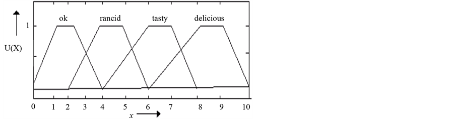
Figure 6. For input variable “ΔVdc”.

Figure 7. Fuzzy coordinated output for firing of VSC.

Table 1. Interference system for fuzzy.
Table 2. Parameters of membership function for fuzzy logic based IPFC.
 (19)
(19)
where, f denotes the mapping defined by the rule base and α, β is the appropriate scaling, which depends on the scale of the X-axis and Y-axis of input and output variables. The fuzzy output is given by equation
 (20)
(20)
5. Simulation Results
For the simulation, three phase fault is considered at bus n2 for the fault duration of 0.05 sec. The simulation results are demonstrated in Figures 8-10.
The proposed PI and Fuzzy controllers performances are tested in multimachine system. Figure 8 depicts the comparative analysis of speed ω1 without IPFC, PI based IPFC, fuzzy based IPFC during abnormal condition. Result indicates that PI based IPFC damps the oscillations and Fuzzy based IPFC reduces first swing from 1.004 rad/sec to 1.0022 rad/sec with settling time 1 sec. Result indicates that fuzzy based IPFC significantly improves the transient stability. System is more amenable with fuzzy logic based IPFC than PI controller as indicated by the response for the speed ω1.
Figure 9 demonstrates the response of generator 2 speed (ω2) under 3 different conditions like without IPFC, with PI, with fuzzy, which depicts that with Fuzzy coordinated controller, response is better than PI controller. Fuzzy based IPFC reduces peak of speed deviation from 1.0022 rad/sec to 1.0015 rad/sec and settles within 1.5 sec. Hence Fuzzy logic based IPFC significantly improves transient stability of the multimachine power system.
The MATLAB result presents the inter area oscillations (dω1 − dω2) during three phase fault of 0.05 sec. duration near bus 2 as shown in Figure 10 for comparative analysis of three cases without IPFC, PI based IPFC, fuzzy based IPFC during abnormal condition which indicates that variation in speed difference of generator-1 and generator-2(dω1 − dω2) with Fuzzy coordinated controller reduces the first swing from  rad/sec to
  rad/sec and oscillations are effectively settled in 1 sec. No. of oscillations with fuzzy based IPFC are significantly reduced.
Figure 11 and Figure 12 indicates the D.C. voltage (Vdc) response. Under normal system conditions Vdc is stable and constant whereas during disturbance, Vdc variation is observed. Vdc helps to supply real power during disturbance condition to VSC2. In fuzzy based IPFC, Vdc variation is little larger than PI based IPFC.
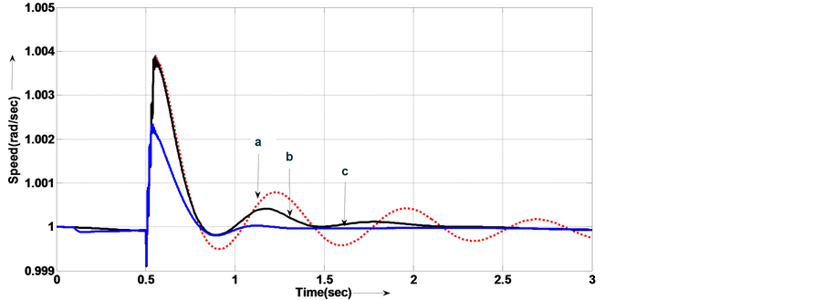
Figure 8. Speed deviation response for speed ω1. Without IPFC b. with PI based IPFC c. with Fuzzy based IPFC.
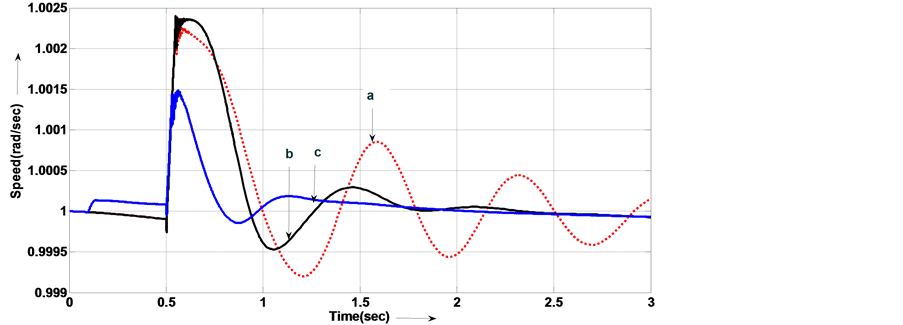
Figure 9. Speed deviation response for speed ω2. Without IPFC b. with PI based IPFC c. with Fuzzy based IPFC.
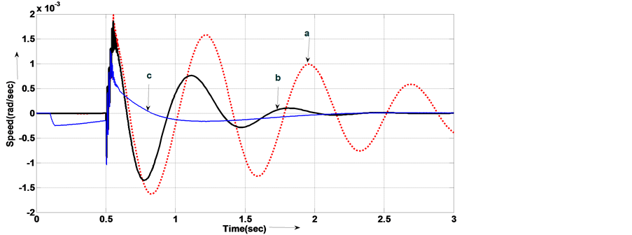
Figure 10. Speed deviation response for speed (dω1 − dω2) Without IPFC b. with PI based IPFC c. with Fuzzy based IPFC.
6. Conclusion
A fuzzy logic based controller for Interline Power Flow Controller (IPFC) has been proposed for multi-machine system to improve power system performance. The fuzzy rules have been designed with two inputs change in

Figure 11. Variation of Vdc with PI based IPFC.

Figure 12. Variation of Vdc with fuzzy based IPFC.
voltage  and change in capacitor voltage
  to minimize transients swing, improvement in damping of oscillations. The controllers comparative performance i.e., PI based IPFC and fuzzy logic based IPFC in terms of transient stability improvement and damping of oscillations is demonstrated. The proposed fuzzy logic controller performance with effective rule base is comparatively better than PI based controller. The fuzzy logic controller demonstrates the robust performance and is easy to coordinate with damping schemes.
Acknowledgements
Authors are thankful to Dept. of Electrical Engg., G. H. Raisoni College of Engineering, Nagpur for their constant support.
Cite this paper
S. N. Dhurvey,V. K. Chandrakar, (2016) Improvement of Power System Performance Using Fuzzy Logic Based Interline Power Flow Controller [IPFC]. Journal of Power and Energy Engineering,04,67-77. doi: 10.4236/jpee.2016.44007
References
- 1. Kundur, P. (1994) Power System Stability and Control. Mc Graw-Hill, New York, 12.
- 2. Hingorami, N.G. and Gyugyi, L. (2001) Understanding FACTS: Concepts and Technology of Flexible AC Transmission System. IEEE Power Engineering Society, Delh.
- 3. Song, Y.H. and Johns, A.T. (1999) Flexible AC Transmission Systems. IEE Power and Energy Series, 30.
- 4. Parimi, A.M., Elamvazuthi, I. and Saad, N. (2008) Damping of Inter Area Oscillations Using Interline Power Flow Controller Based Damping Controllers. IEEE 2nd International Power and Energy Conference, 67-72.
- 5. Gomathi, V., Ramachandran, V. and Kumar, C.V. (2010) Simulation and State Estimation of Power System with Interline Power Flow Controller. 45th International Universities Power Engineering Conference (UPEC), 1-6.
- 6. Chen, J.H., Lie, T.T. and Vilathgamuwa, D.M. (2002) Basic Control of Interline Power Flow Controller. IEEE Power Engineering Society Winter Meeting, 521-525.
- 7. Vasquez-Arnez, R.L. (2008) The Interline Power Flow Controller: Further Aspects Related to Its Operation and Main Limitations, T&D. IEEE/PES Transmission and Distribution Conference and Exposition, 1-6.
http://dx.doi.org/10.1109/tdc.2008.4517091 - 8. Aminifar, F., Fotuhi-Firuzabad, M., Nasiri, R. and Khodaei, A. (2008) Effect of Interline Power Flow Controller (IPFC) on Interconnected Power Systems Adequacy. 2nd IEEE International Conference on Power and Energy (PECon 08), Johor Baharu, 1-3 December 2008, 1358-1363.
- 9. Segundo, F.R. and Messina, A.R. (2009) Modeling and Simulation of Interline Power Flow Controllers: Application to Enhance System Damping. North American Power Symposium (NAPS), 1-6.
http://dx.doi.org/10.1109/NAPS.2009.5484063 - 10. Chandrakar, V.K. and Kothari, A.G. (2006) Improvement of Transient Stability Using Fuzzy Logic Based Unified Power Flow Controller [UPFC]. International Journal Power and Energy Systems, 5, 1-8.
- 11. Chandrakar, V.K. and Kothari, A.G. (2006) Fuzzy-Based Static Synchronous Compensator (STATCOM) for Improving Transient Stability Performance. International Journal Energy Technology and Policy, 5, 692-707.
http://dx.doi.org/10.1504/IJETP.2007.015623 - 12. Chandrakar, V.K. and Kothari, A.G. (2007) Comparison of RBFN and Fuzzy Based STATCOM Controllers for Transient Stability Improvement. IEEE Aegean Conference on Electric Machines Powers and Electromotion, Bodrum,.
http://dx.doi.org/10.1109/acemp.2007.4510556 - 13. Dhurvey, S.N. and Chandrakar, V.K. (2008) Performance Comparison of UPFC in Coordination with Optimized POD and PSS on Damping of Power System Oscillations. International Journal of WSEAS Transaction on Power System, 3, 287-299.
- 14. Dhurvey, S.N. and Chandrakar, V.K. (2011) Performance Evaluation of IPFC by Using Fuzzy Logic Based Controller. IEEE 4th International Conference on Emerging Trends in Engineering & Technology, ICETET 2011, Mauritius, 168-173.
- 15. Menniti, D., Pinnarelli, A. and Sorrentino, N. (2002) A Fuzzy Logic Controller for Interline Power Flow Controller Model Implemented by ATP-EMTP. International Conference on Power System Technology, 3, 1898-1903.
- 16. Mishra, S., Dash, P.K., Hota, P.K. and Tripathy, M. (2002) Genetically Optimized Neuro-Fuzzy IPFC for Damping Modal Oscillations of Power System. IEEE Transactions on Power Systems, 17, 1140-1147.
http://dx.doi.org/10.1109/TPWRS.2002.804958 - 17. Naresh Babu, A.V. and Sivanagaraju, S. (2011) Mathematical Modelling, Analysis and Effects of Interline Power Flow Controller (IPFC) Parameters in Power Flow Studies.
- 18. Yadaiah, N. and Venkata Ramana, N. (2007) Linearisation of Multi-Machine Power System: Modeling and Control—A Survey. International Journal of Electrical power and Energy Systems, 29, 297-311.
http://dx.doi.org/10.1016/j.ijepes.2006.06.011 - 19. Mansour-Khalilian, Maghsoud-Mokhtari, Daryoosh-Nazarpour and Behrouz-Tousi (2010) Transient Stability Enhancement by DSSC with Fuzzy Supplementary Controller. Journal of Electrical Engineering & Technology, 5, 415-422.
http://dx.doi.org/10.5370/JEET.2010.5.3.415 - 20. Thakre, M.P., Kale, V.S., Dhenuvakonda, K.R., Umre, B.S. and Junghare, A.S. (2015) Study and Mitigation of Subsynchronous Oscillations with SSC Based SSSC. Journal of Power and Energy Engineering, 3, 33-43.
http://dx.doi.org/10.4236/jpee.2015.39003
Appendix
A.1. Synchronous Machine-I-2100MVA(M1)-Stator resistance-2.8544e−3, Inertia constant H(s) = 3.7, Line to line voltage (Vrms) = 13,800 V, frequency fn(HZ) = 60
Synchronous Machine-II-1400 MVA(M2)-Stator resistance-2.8544e−3, Inertia constant H(s) = 3.7, Line to line voltage (Vrms) = 13,800 V, frequency fn(HZ) = 60
A.2. Transmission line parameter-No. of phase-3
Length of transmission line-L1 = 280-km, Resistance per unit length (Ohms/km)-R1 = 0.01273*2, R0 = 0.3864, Inductance per unit length (H/km)-L1 = 0.9337e−3, L0 = 4.1264e−3
Capacitance per unit length (F/km)-C1 = 12.74e−9, C0 = 7.751e−9
L2 & L3 = 150 km-Resistance per unit length (Ohms/km)-R1 = 0.01273*2, R0 = 0.3864,
Inductance per unit length (H/km)-L1 = 0.9337e−3, L0 = 4.1264e−3,
Capacitance per unit length (F/km)-C1 = 12.74e−9, C0 = 7.751e−9
L3 = 50 km-Resistance per unit length (Ohms/km)-R1 = 0.01273*2, R0 = 0.3864,
Inductance per unit length (H/km)-L1 = 0.9337e−3, L0 = 4.1264e−3
Capacitance per unit length (F/km)-C1 = 12.74e−9, C0 = 7.751e−9
A.3. Rating of the loads
Three-phase parallel RLC load (star)-250 MW, Nominal phase-to-phase voltage = 500 e3V, Active power = 250 e6W, Three-phase parallel RLC load (star)-100 MW, Nominal phase-to-phase voltage = 500 e3V, Active power = 103 e6W
Three-phase Dynamic load-Nominal L-L voltage = 500 e3V, Active power = 2.2e+009 W, Reactive power = 1e+008 var
A.4. Rating of IPFC
1000 MVA, DC link nominal voltage = 40 KV, equivalent capacitance = 375 µF, equivalent impedance = 0.16 pu
A.5. Parameters of PI controller
AC regulator-[Kp Ki] = [0.00375 0.1875], DC regulator-[Kp Ki] = [0.1e−3 20e−3]