Optics and Photonics Journal
Vol.05 No.04(2015), Article ID:56049,11 pages
10.4236/opj.2015.54015
Study and Design of Hybrid Triplet Lens
Nuha F. Al. Al-Hariby, Abed M. Kassim, Issam H. Al-Ahdali*
Physics Department, Faculty of Applied Sciences, Umm Al-Qura University, Makkah, Saudi Arabia
Email: *issamhamid1950@yahoo.com
Copyright © 2015 by authors and Scientific Research Publishing Inc.
This work is licensed under the Creative Commons Attribution International License (CC BY).
http://creativecommons.org/licenses/by/4.0/


Received 2 January 2015; accepted 27 April 2015; published 30 April 2015
ABSTRACT
This study presents a new method for designing algorithm for a triplet lens with one or two elements that are made of a gradient index medium (GRIN). This method is based upon considering a well-known designed triplet lens (Cooke triplet lens) as a target lens for designing of the Hybrid Triplet Lens (HTL). Our design was based upon keeping the total optical path length for the axial ray fixed for each case of design. The results showed that several designs for the HTL have the same total powers of the target lens. These designs depend on the variation of the GRIN element parameter values and the order of the GRIN element position in the system. These HTL designs have been evaluated by considering several optical merit functions, i.e., the root mean square (RMS) spot radius, wave front error and the spherical aberration. To achieve the optimal design, these functions are compared for the target lens and the HTL designs through a wide range of field angles.
Keywords:
Design Algorithm, Cooke Triplet Lens, Hybrid Triplet Lens, Gradient Index Medium

1. Introduction
All optical glasses are characterized by a physical quantity which is known as refractive-index. This refractive index of such a medium depends on the electrical and magnetic properties of the medium [1] . When the refractive index is independent of the coordinates in the medium, this medium is called homogeneous medium. Otherwise, a medium, in which the refractive index varies from point to point within the medium, is called inhomogeneous medium. The term “gradient index” or “graded index” is often used to describe such medium, i.e., GRIN medium. GRIN glasses may be divided into two general categories: radial and axial [2] . Both types of GRIN’s are limited in the maximum change of the refractive index. Optical glasses containing very large axial property gradients had been commercially available since 1996. These glasses are formed by a layer diffusion process [3] . The properties, specification and tolerances of GRIN glass are reported. Many effective lens design examples using gradient-index (GRIN) materials had been reported so far [4] . However, the GRIN materials that were used in those designs are very difficult to produce. These materials possess an index of refraction and varies spatially [1] [5] . By providing additional design variables, GRIN lenses can improve the optical system performance and reduce the number of the optical surfaces in such system while maintaining its power fixed [5] . GRIN lenses were used to eliminate spherical aberration and the methods of manufacturing these lenses had been reported. In order to realize these benefits, however, manufacturing tolerances for gradient-index lenses are required [6] . GRIN lenses represent an interesting alternative to the use of aspheric surface (surface of a variable curvature) in lens design, since the lens performance depends on a continuous change of the refractive index within the lens material [7] . The Cooke triplets a photographic lens design designed and patented in 1893 by Dennis Taylor [8] [9] . It was the first lens system that allows elimination of most of the optical aberration. This lens is composed of three elements (three single lenses). Despite the fact that the Cooke design was patented in 1893, it seems that the use of achromatic triplet designs in astronomy appeared as early as 1765. The 1911 Encyclopedia Britannica wrote [8] , the triplet object-glass, consisting of a combination of two convex lenses of crown glass with a concave flint lens between them, was introduced in 1765 by Peter, son of John Dollond, and many excellent telescopes of this kind were made by him. Nowadays, the design and performance of a Cooke triplet have a wide range application as a component in the electro-optical instruments [9] . To optimize such a lens (improving its image quality), the optical designers have to vary a lot of parameters, i.e., the six curvatures of the elements surfaces and the two inner spacing between elements. This technique of lens optimization requires a lot of computational work [10] . In the last decades, a new technique [11] for designing single lenses, which are made of gradient index material (GRIN) has been developed by optical designer. This technique showed its power as a good tool for reducing the geometrical aberrations of lenses. Thus, the optical performance of the GRIN optical systems has been improved to a great extent. The goal of this research is to design a triplet lens with one or two GRIN elements which is called Hybrid Triplet Lens (HTL). Then, to optimize such design, two factors are considered: the position of the GRIN element in the HTL and the GRIN parameter of this element. The optical path length and the total powers of the target and HTL designs are kept constant. This study represents the design procedure that describes the technique used to design the HTL and the results analysis related to the HTL designs. A theoretical discussion for a ray aberration is described for the case of on- and off-axis rays incident upon the optical system. Since the optimization techniques of such an optical system are based upon reducing the ray aberrations, therefore a description of such aberrations is classified and given graphically in this study. And also, a brief discussion for techniques used in optical design to evaluate images formed by such an optical system is presented. Specifically, the optical designers are using many merit functions [9] to optimize such a system, i.e., RMS spot radius, wave front error and spherical aberrations transverse spherical aberrations (TSA) and longitudinal spherical aberrations (LSA). The design procedure of this study is introduced, and a new method for designing a hybrid triplet lens is presented. The mathematical procedures for such design are described. The optical path length of the axial ray and the total powers for the target lens and proposed HTL are kept constant, the parameters of the HTL are specified. Many designs for HTL have been obtained, through the control of the GRIN element position in the HTL and the variation of GRIN parameters, i.e., considering the positive and negative values. Then, the layout parameters of these new designs are tabulated; namely: front, mid, back and front-back GRIN element (with positive and negative GRIN parameters). Also, in this article, the image quality, formed by each new design of the HTL, has been compared graphically with that of the target lens for a wide range of field angles (0˚ - 20˚). In this study, for a comparison reason, the previous well-known optical merit functions have been evaluated for this range of field angles. These comparisons predict the optimal design of the HTL, i.e., the best location of GRIN element and its GRIN parameter for this range of field angles. In this work, a computational program is written to evaluate the ray trace technique [12] [13] in a GRIN lens. The results obtained by this program were in very good agreement with that of the software ZEMAX program [14] which is used in this study for computing the previous optical merit functions.
1.1. Cooke Triplet Design
The Cooke triplet cementing three lenses, is a photographic lens designed in 1893 by Dennis Taylor [9] . This lens comprises a negative flint glass element in the Centre with a crown glass element on each side (see Figure 1), thus maintaining a large amount of symmetry. In this design, the sum of all the curvatures times indices of refraction can be zero [9] , so that the field of focus is flat. In other words, the negative lens can be as strong as the outer two combined, when one measures in diopters.

Figure 1. Scheme of a Cooke triplet lens.
The two positive elements must be made of a crown type glass which has a lower dispersion or higher Abbe number, and the negative element must be made of a flint type glass which has a higher dispersion or lower Abbe number [15] . The sizes of the airspaces in a Cooke triplet are a strong function of the dispersion difference between the crown and flint glasses. The difference in index of refraction between the crown and flint glasses enters into the optical solution. The positive elements should be made of a higher-index crown glass, and the negative element should be made of lower-index flint glass. Experience has shown that higher-index crown glasses gives better image quality, Petzval sum condition [9] reduces higher-order aberration. Given the crown glass selection, the basic optical design requires a matching flint having a certain dispersion difference and a low index. The optimized triplet lens, in which aberrations may be corrected, consists of two positive crown elements on either side of, and spaced away from, a negative flint element.
1.2. Grin Concepts and Applications
In spite of knowing the concepts of GRIN long time ago, its implementation in the optical systems started within the last three decades. And, the stages of the GRIN using in lens design and the technique for its manufacturing have been discussed in reference [1] . A computerized method for tracing ray through GRIN media has been developed by Sharma, et al. (1982) [12] . This method is based upon the numerical solution of ray equation. Thus, the evaluation of such an optical system with GRIN medium is eased. In the literature [4] [16] [17] , several GRIN optical system have been designed and manufactured.
2. Gradient Index Types
Since in GRIN glasses, the refractive index,  , varies with the position within the glass. Then, the GRIN glasses may be divided in two general categories [1] : one is an axial GRIN medium, which the refractive index is a function only of distance
  from a fixed plane, i.e.; the gradient is along the optical axis of the lens (see Figure 2). the other is radial GRIN medium, refractive index is a function of the radial distance from the optical axis
  (see Figure 2). The distribution equations for both of them, can be expressed as:
 (1)
(1)
for an axial gradient index where ,
,  ,
,  ,
,  are constants which are known as GRIN parameters. And for radial GRIN Medium with cylindrical symmetry, can be expressed as:
 (2)
(2)
where ,
,  ,
,  ,
,  are constants which are known as GRIN parameters.
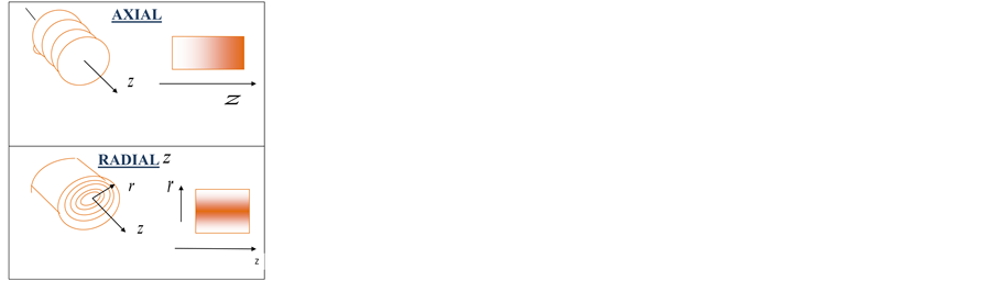
Figure 2. Comparison of axial and radial refractive index gradient.
In lens design, the axial gradient-index lens has two important advantages. First, the curved lens surfaces still, focusing performance is far deviations. Second, axial gradient-index material can theoretically be fabricated in any size or thickness.
Ray Trace in Grin Medium
The path of the rays in a GRIN medium is obtained by solving the ray equation (Equation (3)). Since this equation is not in a convenient form for direct numerical integration, Sharma [12] has described a numerical method for solving this equation. It is a standard Runge-Kutta [18] method to three dimensions. Given the initial ray data, Runge-Kutta techniques prescribe sampling the field at a specified number of places in the neighborhood of the initial position. This information is then used to find approximate ray data a distance  away. Using the notations given [19] the mathematical procedures which give the ray trace equation in GRIN medium are summarized as follows:
The vectorial form of the ray equations is:
 (3)
(3)
which can be written as
 (4)
(4)
where  is the position of the ray,
  is an infinitesimal arc length, along the trajectory, divided by the index. Then, let
  represents the optical direction cosines, i.e.,
 (5)
(5)
Also, the right hand side of Equation (4) can be represented as:
 (6)
(6)
Using these notation, Equation (4) can be rewritten as:
 (7)
(7)
Since this is a second-order differential equation, the initial position and direction are required in order to specify a solution. The Runge-Kutta prescription for the position and direction of the ray often  steps in terms of the position and direction often
  steps can be written as:
 (8)
(8)
 (9)
(9)
where ,
,  and
and  are given by:
 (10)
(10)
In this study, Equations (8)-(10) are used to design a FORTRAN program which evaluate the ray trace through an axial GRIN medium for various field angles. In reference 17, an algebraic solution for the ray equation in a linear axial GRIN medium,  , is presented in detail. Also, a general ray trace in GRIN medium is given for off-axis incidence.
3. Results and Analysis
In this work, various designs of hybrid triplet lenses (HTL), based upon a well-designed triplet lens (target lens), will be presented. In these designs, one or two elements of GRIN lens replaces the original elements in the target lens. The optical path length of the target triplet lens, measured from the vertex of the first element surface to the vertex of the last element surface, is kept constant for all the presented HTL designs. These HTL designs are evaluated by using different merit functions, i.e., (RMS) of the spot diagram, wave front error, TSA and LSA.
4. Design Procedures
In this study, a well-known triplet lens (designed in Ref. [9] ) is used as a target lens. The parameters of this lens are given in Table 1.
The procedures for designing a hybrid triplet lens, where one element is replaced by GRIN element, are summarized as follow; considering the definition of the optical path length [19] (OPL) of the axial ray through the triplet lens,  , one has:
 (11)
(11)
where  and
and  are the thickness and the refractive index to the right of ith the optical surface (see Figure 1). For the proposed hybrid triplet lens with a GRIN element, the OPL of this ray through this element is computed as:
 (12)
(12)
where  is the GRIN elementthickness.
Using linear axial GRIN and by direct integration, Equation (12) gives:

Table 1. Target lens layout parameters.
 (13)
(13)
In our study, we equate the OPL of the axial ray through the target triplet lens with the OPL of this ray through the proposed hybrid triplet design. Applying this condition, the thickness  of the GRIN element used in the proposed design is computed, while the values of
  are considered to be equal to the refractive indices of the original elements. For comparision reason, the values of GRIN parameter,
  , is specified as
  ,
,  and
and  for all proposed HTL designs.
4.1. Hybrid Triplet Lens Design
Following the previous procedures, the layout parameters for various hybrid triplet lenses designs are given in Table 2. The colored raws in all tables show the parameters of the GRIN element and its locationin the HTL design.
All parameters of a mid GRIN element of triplet lens are calculated (see in Table 2). The designs (a) and (b) in Table 2 are related to positive and negative GRIN parameters respectively.
4.2. Results Analysis
The optical performance of hybrid triplet lens (HTL) is evaluated by considering the following merit functions:
4.2.1. The RMS Spot Radius
Figure 3 shows comparison between the corresponding values of the RMS spot radius as function of field angles for the following lenses. Target lens (red line), the HTL with positive mid GRIN element, i.e., (designs 6-a), and the HTL with negative mid GRIN element, i.e. (designs 6-b). Referring to this figure, as the values of GRIN parameters increase positively, the corresponding values of RMS spot radius increase for all field angles. Whereas, through the field angle ranges (0˚ - 12˚), the values of RMS spot radius increase as the values of GRIN parameters increase negatively. Through the field angle range (0˚ - 6˚), the values of RMS spot radius for positive and negative GRIN elements are almost close to each other and really equal to its corresponding values of the target lens. This indicates that the use of GRIN element has a slight effect on the optical performance of the target lens. Also, through the field angle range (12˚ - 15˚), the values of RMS spot radius for the GRIN design 4b  are greater than its corresponding values of the GRIN design 5b
 . But, through the field angles range (15˚ - 20˚), the values of RMS spot radius for the GRIN design 6b
  are greater than its corresponding values of the GRIN design 5b
 . Through the field angle range (10˚ - 20˚), the values of RMS spot radius for the GRIN designs (4b-6b) are less than its corresponding values for the target lens, i.e., the GRIN design 5b is more optimized compared with the design 6-b.This indicates that the design of the HTL with negative mid GRIN element will improve the optical performance for this high range of field angles (wide field angle).
4.2.2. The RMS Wave Front Error
Figure 4, compares the corresponding values of the RMS wave front error as function of field angles (0˚ - 20˚) for the following lenses. Target lens, the HTL with positive mid GRIN element, i.e., (designs 6-a), and the HTL with negative mid GRIN element, i.e., (designs 6-b). Referring to this figure, as the values of GRIN parameters increase positively, the values of RMS wave front error increase. Whereas, through the field angle range (0˚ - 15˚), the values of RMS wave front error increase as the values of GRIN parameters increase negatively. Also, through the field angle range (15˚ - 19˚), the values of RMS wave front error for the GRIN design 4b  are greater than its corresponding values of the GRIN design 5b
 . But, through the field angle range (19˚ - 20˚), the values of RMS wave front error for the GRIN design 6b
  are greater than its corresponding values of the GRIN design 5b
 . Through the field angle range (0˚ - 3˚), the values of RMS wave front error for positive and negative GRIN elements are almost equal to its corresponding values of the target lens. Also, through the field angle range (3˚ - 8˚), the values of RMS wave front error for the GRIN design 4a
  are less than its corresponding values for the target lens, through the field angle range (10˚ - 20˚). The values of RMS wave front error for the GRIN designs (4b-6b) are less than its corresponding values for the target lens, through the field angle range (10˚ - 15˚). This gives that GRIN design 4b is more op- timized compared to the design 5-b. Whereas through the field angle range (15˚ - 20˚), the GRIN design 5b is
Table 2. Layout parameters for the mid GRIN triplet lens design for zero field angle.
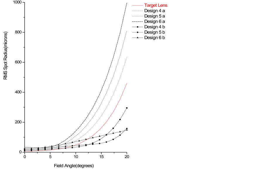
Figure 3. Comparison between the corresponding values of RMS Spot Radius for the target lens and the mid GRIN triplet design as function of field angles.
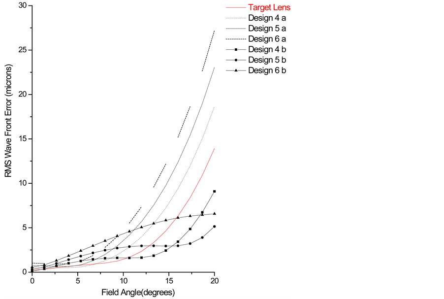
Figure 4. Comparison between the corresponding values of RMS Wave Front Error for the target lens and the mid GRIN triplet design as function of field angles.
more optimized compared to the design 6-b. As a result of this study, it is recommended to use mid negative HTL design as an optimized technique in optical design for a triplet lens.
4.2.3. Transverse Spherical Aberration (TSA)
Figure 5 compares the corresponding values of the transverse spherical aberration (TSA) as a function of the aperture radius at zero field angle for the following lenses. Target lens and the HTL with positive mid GRIN element, i.e., (designs 6-a), and the HTL with negative mid GRIN element, i.e., (designs 6-b). According to this figure, it is noticed that the corresponding values of  increase as the absolute values of GRIN parameters,
  , increase through the whole range of aperture radius. But, for a small aperture radius (paraxial rays), the corresponding values of
 , for these lenses, are almost equal. Also, at the middle of aperture radius, the values of TSA for the design 5b
  are less than its corresponding values for the target lens. Whereas, for a large aperture radius (non-paraxial rays), these corresponding values of
  are deviated. But, the values of TSA for the design 4b
  are less than its corresponding values for the target lens. Also, the design 5b
  is more optimized compared with the design 4-b
 . This implies that this design (5-b) of the HTL will improve the optical performance of the target lens.
Figure 6 compares the corresponding values of the transverse spherical aberration (TSA) as a function of the aperture radius at field angle 200 for the following lenses. Target lens, the HTL with positive mid GRIN element, i.e., (designs 6-a), and the HTL with negative mid GRIN element, i.e., (designs 6-b). Referring to this figure, it is noticed that the corresponding values of  increase as the absolute values of GRIN parameters,
  , increase through the whole range of aperture radius. But, for a small aperture radius (paraxial rays), the corresponding values of
 , for these lenses, are almost equal. But, at the middle aperture radius, the values of TSA for the GRIN design 5-b are less than its corresponding values for the target lens. Whereas, for a large aperture radius (non-paraxial rays), these corresponding values of
  are deviated. But, the values of TSA for the design 6-b are less than its corresponding values for the target lens. Also, the design 5-b is more optimized compared with the design 6-b. This implies that this design (5-b) of the HTL will improve the optical performance of the target lens.
4.2.4. Longitudinal Spherical Aberration (LSA)
Figure 7 shows values of the longitudinal spherical aberration (LSA) as a function of the upper half of the aperture
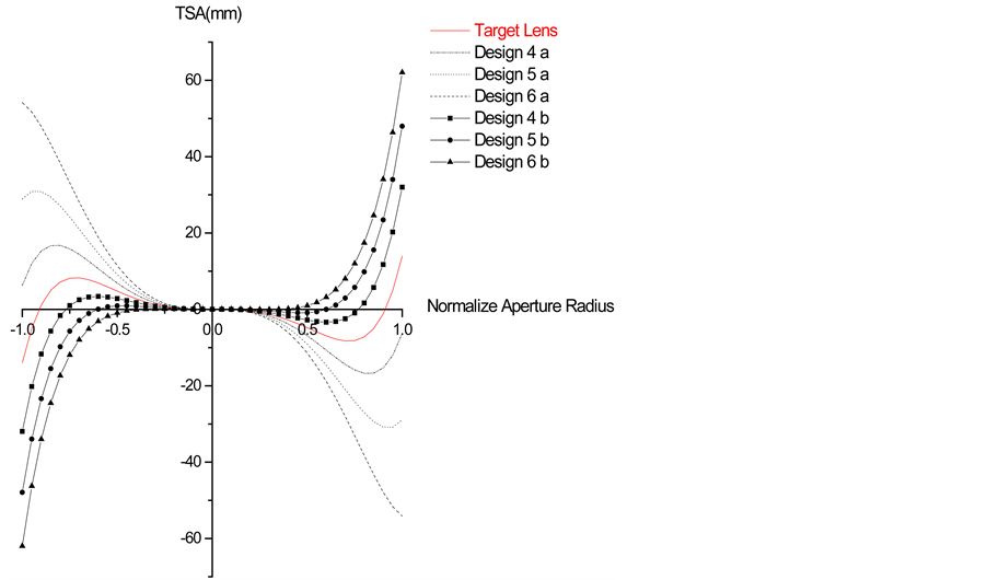
Figure 5. Comparison between the corresponding values o TSA for the target lens and the mid GRIN triplet design as function of aperture radius at zero field angle.
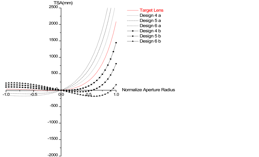
Figure 6. Comparison between the corresponding values of TSA for the target lens and the mid GRIN triplet as function of aperture radius at field angle = 20˚.
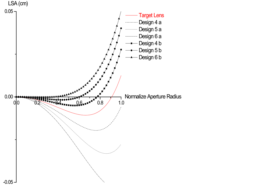
Figure 7. Comparison between the corresponding values of LSA for the target lens and the mid GRIN triplet design as function of upper half of the aperture radius for zero field angle.
radius, for zero field angles, for the following lenses. Target lens, the HTL with positive mid GRIN element, i.e., (designs 6-a), and the HTL with negative mid GRIN element, i.e., (designs 6-b). Referring to this figure, it is noticed that the corresponding values of  increase as the absolute values of GRIN parameters,
  , increase through the whole range of aperture radius upper half. But, for a small aperture radius (paraxial rays), the corresponding values of LSA, for these lenses, are almost equal. But, at the middle aperture radius, the values of LSA for the designs (6-b) are less than its corresponding values for the target lens. Whereas, for a large aperture radius (non-paraxial rays), these corresponding values of LSA are deviated. As a result of this study, the LSA is reduced by using a mid GRIN triplet lens with a negative GRIN parameter for small values of aperture radius. But, the HTL is free of LSA
  at a normalized aperture radius with a value which is less than that of the target lens. Also, this value of the normalized aperture radius decreases as the value of GRIN parameter,
  , increases negatively.
5. Conclusion
The result of this study reveals that it is technically possible to design a hybrid triplet lens (HTL) for a wide field angles. Also, it proves that the image quality of this design is effected to a large extent by the location of the GRIN in this lens. The optimal design of the HTL is achieved when the GRIN element is placed at the mid of the triplet lens, since this design will maintain the symmetry of the optical system. The other proposed designs of the HTL have a bad image quality compared to that of the target lens. Also, this study proves that the image quality of the proposed designs of the HTL is good for the large values of field angles, when the GRIN has a negative value. The design of HTL proves that it is more effective than other conventional optimal techniques for the triplet lens designs in case of wide range field angles. Therefore, for optical designer, it is recommended that the optimal design of the HTL is accomplished by using a GRIN element in the mid-location of the system and with negative GRIN parameter.
References
- Marchand, E.W. (1987) Gradient Index Optics. Academic Press, New York.
- Gordon, J.M. (2000) Spherical Gradient Index Lenses as Perfect Imaging and Maximum Power Transfer Devices. Applied Optics, 39, 3825-3831.
- Wade, R.K., Hunter, B.V., Walters, B. and Fournier, P. (1998) Properties, Specifications, and Tolerances of Radium Glasses. Light Path technologies, Inc., 6820, Academy Parkway e., NE, Albuquerque.
- Jpn, J. (1998) Design of Imaging Lens Systems That Use Low Dispersive Radial Gradient-Index Rod. Japanese Journal of Applied Physics, 37, 3633-3637.
- Crawford, M.K. (2000) Tolerance Analysis of Axial Gradient-Index Lenses. Ph.D. Thesis, The University of Rochester, Rochester, NY. Source DAI-B 61/02, p 914, 188 pages. 34.
- Moore, D.T. (1974) Gradient Index Optics: Aspects of Design, Testing, Tolerancing, and Fabrication. Ph.D. Thesis, Rochester Univ., NY.
- Wang, Y.-Z. and Wang, X. (1997) Improvements on the Ray Tracing Procedure for High-Order Aspheric Surfaces. Optical Engineering, 36, 2259-2260. http://dx.doi.org/10.1117/1.601450
- Kingslake, R. (1989) A History of the Photographic Lens. Academic Press, New York.
- Kingslake, R. (1983) Lens Design Fundamentals. Academic Press, New York.
- U.S Government Printing Office (1962) Military Standardization Hand Book: Optical Design, MIL-HDBK-141.5. U.S Government Printing Office, Washington DC.
- Foreman Jr., J.W. (1974) Computation of RMS Spot Radii by Ray Tracing. Applied Optics, 13, 2585-2588. http://dx.doi.org/10.1364/AO.13.002585
- Sharma, A., Kumar, D.V. and Ghatak, A.K. (1982) Tracing Rays through Gradient-Index Media: A New Method. Applied Optics, 21, 984-987.
- Stone, B.D. and Forbes, G.W. (1990) Optimal Interpolants for Runge-Kutta Ray Tracing in Inhomogeneous Media. Optical Society of America, Washington DC.
- ZEMAX (2001) Optical Design Program―Version 10.0. Focus Software, Incorporated, Arizon.
- Born, M. and Wolf, E. (1980) Principle of Optics. 6th Edition, Pergaman Press, Oxford.
- Fisher, D.J., Harkrider, C.J. and Moore, D.T. (2000) Design and Manufacture of Gradient-Index Axion. Applied Optics, 39, 2687-2693.
- Krishna, K.S.R. and Sharma, A. (1996) Low-Power Gradient-Index Microscope Objective: Design. Applied Optics, 35, No.28,. http://dx.doi.org/10.1364/AO.35.005636
- Al-Hajaji, H.A.A. (2003) The Characteristics of Rays Paths in a GRIN Medium. Thesis, Um-Al-qura University, Mecca.
- Mayer-Arendt, J.R. (1972) Introduction to Classical and Modern Optics. Prentice-Hall, INC., Englewood Cliffs.
NOTES

*Corresponding author.