Geomaterials
Vol. 2 No. 4 (2012) , Article ID: 24039 , 4 pages DOI:10.4236/gm.2012.24016
Instability Analysis of Damaged Pile Due to Static or Dynamic Overload
1Civil Engineering Department, University of Agriculture, Makurdi, Nigeria
2Electrical Engineering, University of Agriculture, Makurdi, Nigeria
Email: *peterjiki@yahoo.com
Received June 15, 2012; revised August 16, 2012; accepted August 26, 2012
Keywords: Damaged Piles; Earthquake Overload; Instability Analysis; Layered Soil Support
ABSTRACT
Instability of a damaged pile due to a statically or dynamically applied overload is studied in this work using the finite element method. A damage parameter from such a pile is calculated using fracture mechanics concepts. The parameter is used to modify the beam element at the cracked or damaged location. Soil samples were obtained from the site of the pile and were subjected to laboratory tri-axial tests to obtain shear strength parameters c and . Other soil parameters such as Young’s modulus E and Poisson’s ratio
  were also obtained from the tri-axial tests. These were used to calculate shear strength
  and sub-grade modulus k for the soil. The parameters
 , E,
, E,  and k were later used together with the damage parameter
  in the finite element simulation of the strength of the damaged pile using Eigen value analyses. The layered soil modulus is approximated by taking the mean value and is denoted by
 . The discrete element matrices are assembled into a system Eigen-value equation, the solution of which provides the stability or instability loads for the damaged pile. The results obtained for a pile without damage, that is, when
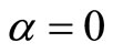 , are in good agreement with those published in the literature. It has also been found that higher soil resistance is needed to support the damaged pile. It is concluded that the proposed model is a good candidate for use in the analysis and repair of damaged piles due to earthquake overload by soil stabilization methods.
1. Introduction
Recently, earthquakes and Tsunamis have caused severe damages to some infrastructures around the world such as the quake in Haiti and the Tsunami in Japan. Some of these infrastructures suffer damage but do not collapse, particularly if the infrastructure is a pile being supported by the surrounding layered soil. Some of these infrastructures on pile supports that suffer damage include nuclear power stations (such as those in Japan), bridge piers and offshore platforms (see Smith [1]).
In recent years, Burgess [2,3] has drawn attention to the possibility of instability occurring during installation of slender piles. He assumes the ground shear resistance always act tangentially to the pile, rather than in a fixed (vertical) direction. This means that the instability can be of the “wandering” or “flutter” variety rather than classical buckling and requires a dynamic analysis to isolate the loads at which loss of stability occurs. A description of the mechanics of non-conservative instability and some closed form solutions for simple columns are to be found in Leipholz [4]. The addition of constant lateral (Winkler) stiffness was studied by Smith and Herrmann [5]. Deriving discrete beam element matrices, Smith [6] has studied the onset of instability of undamaged piles in uniform ground assuming both conservative and nonconservative cases. The purpose of the present article is to study the behaviour of damaged piles under conservative loads and supported by layered soils.
2. Calculation of Local Stiffness Due to Damage
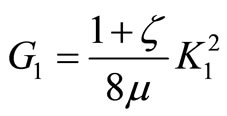
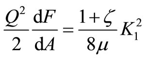
A strip or a rectangular plate representing the damaged portion of the pile has a width b and thickness h with a transverse crack c. It is well known that the compliance derivative of such a strip is related to the strain energy release rate G1 as in Jiki [7]:
 (1)
(1)
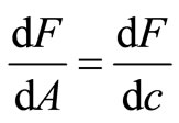
where Q is the driving force, F is the local flexibility due to crack, A is the area of the crack surface. The energy release rate G1 is also related to the stress intensity of the cracked strip as:
 (2)
(2)
in which μ is the shear modulus for the material of the strip;  for plane strain and
  is Poisson’s ratio. From Equations (1) and (2), we have:
 (3)
(3)
For the present work, we work with the unit width of crack. Then the area of the crack A is given as in Jiki [7]:
 (4)
(4)
Then:
 (5)
(5)
Substituting Equation (5) into Equation (3), we have:
 (6)
(6)
From Equation (6) the compliance derivative becomes:
 (7)
(7)
The condition for  implies no crack flexibility. We integrate Equation (7) to get the compliance F as in Jiki [7]:
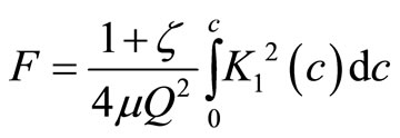 (8)
(8)
For mode 1 due to bending moment M, we have ( Jiki [7], Anifantis and Dimarogonas [8]):
 (9)
(9)
where
 (10)
(10)
Let
 (11)
(11)
Using Equations (9)-(11) into Equation (8) and integrating, we have:
 (12)
(12)
in which
 (13)
(13)
The relationship between stiffness and flexibility is:
 (14)
(14)
Then the non-dimensional stiffness parameter is:
 (15)
(15)
Then the damaged stiffness coefficient for the pile is written as in Jiki [7].
 (16)
(16)
3. Discretization of the Differential Equations
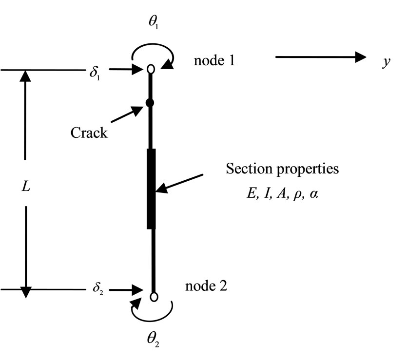
Previous work has typically involved discretization of the complete pile (or column) in terms of Fourier coefficients, for example. A more modern approach, through which existing finite element programs can be utilised, is to discretize locally over a small, typical element, e.g. Figure 1.
For flexural modes the usual discretization involves the transverse displacements  and rotations
  of the end nodes:
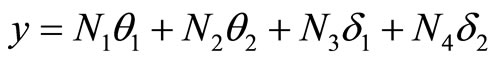 (17)
(17)
In this equation the well-known shape functions  are given by
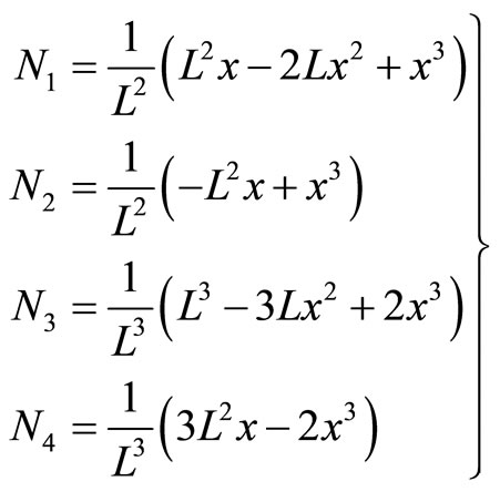 (18)
(18)
Consider, for example, one of the examples analysed by Burgess [3]. This involves linearly varying soil stiffness
 (a)
(a)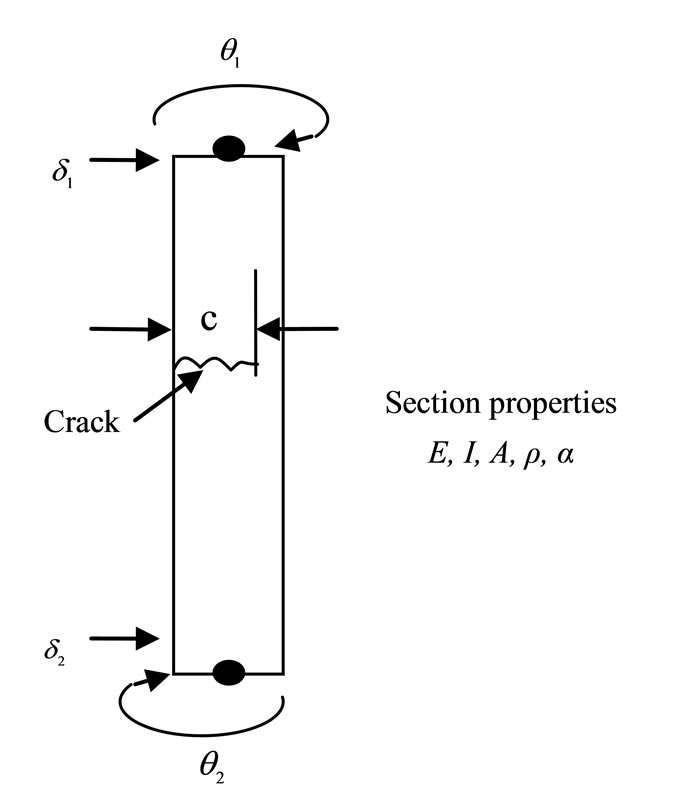 (b)
(b)
Figure 1. (a) Typical discrete flexural line element; (b) Enlarged details of cracked element
k and side shear  with depth. The rates of change of k and
  are mk and
  respectively, and for equal element lengths L the conditions in the i-th element are as shown in Smith [6]. While both Burgess [3] and Smith [6] model undamaged piles on uniform ground under conservative and non-conservative forces, our present model considers the behaviour of damaged piles on layered soil and subjected to conservative forces only. It has been found in the literature that damage to structural components in form of cracks can alter the static strengths of these components as reported in Jiki [7], Capuani and Willis [9] and can also alter the vibration characteristics of these components such as mass and natural frequencies as reported in Anifantis and Dimarogonas [8].
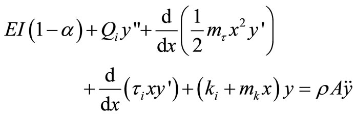
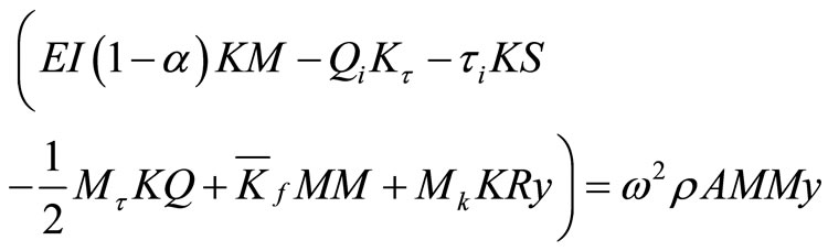
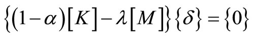
Indeed our model modifies the conservative equation by Timoshenko and Gere [10] with our proposed parameter as:
 (19)
(19)
In Equation (19) the primes represent spatial, and the dots temporal differentiation. From the third and fourth terms in Equation (19) it can be observed that the selfadjointness is a feature usually found in conservative systems.
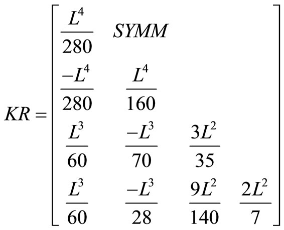
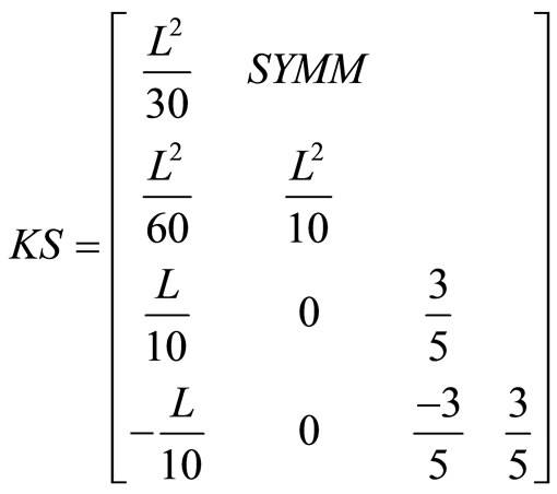
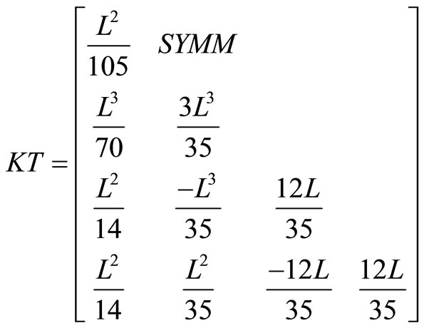
Discretization in terms of the four undetermined nodal parameters of the element is completed by applying the Galerkin’s process in the usual way. The resulting information is tabulated, term by term, as Table 1. For completeness the relevant matrices are listed in Appendix 1, although some are well known, KM and MM being the “stiffness” and “mass” matrices, for example see Smith [6]. While our model has considered the behaviour of a damaged pile on a layered soil, it also has increased difficulty in obtaining samples from different layers of the layered soil for the calculation of shear strength , sub-grade modulus k, Young’s modulus E, Poisson’s ratio
  as well as bearing capacity parameters such as
 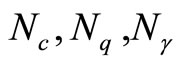 for the soil. These parameters are often obtained from tests or are predicted using the finite element analysis in conjunction with existing equations in the literature as in Jiki et al. [11].
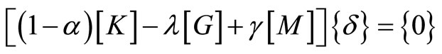
Assuming harmonic motion, the conservative Equation (19) discretizes into element eigenvalue equation
 (20)
(20)
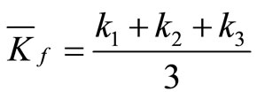
in which  is the average subgrade modulus which is given for the three soil layers shown in Figure 2 as
 (21)
(21)
Element assembly to make up the complete pile follows in the usual way.
Equation (20) represents an unsymmetrical eigenvalue problem which can predict two types of instability, depending on the combinations of the physical parameters ,
,  , etc. Either one of the
  values can become negative (classical buckling instability) or two real
  values can converge and in the limit become equal. Thereafter a further perturbation leads to complex conjugate values of
  (Fiutter instability). In the conservative case (symmetrical eigenvalue problem) only classical buckling can occur. Herein we assume the boundary terms that result from integration by parts in the Galerkin process to be small and are disregarded. Therefore the usual conservative boundary conditions apply to the present work as in Bolotin [12].
After assembly, the eigenvalue equation becomes
 (22)
(22)
For buckling we have:
 (23)
(23)
For vibration we have:
 (24)
(24)
4. Results and Discussion
Using the above matrices and the calculated damage parameter α, many examples have been solved with twelve beam elements or more per pile. This has resulted in all cases in instability predictions that are in good agreement with published work by Smith [6] when we set our crack or damage parameter to zero. For example, Figures 3-5 show instability predictions for piles in a layered soil subjected to conservative loads only. In our work here, we have approximated the layered soil by taking the mean sub-grade modulus to represent soil strength (Winkler model) needed to support the damaged pile. Therefore in Figures 3-5, when the crack parameter is zero, our model approaches that by Smith [6]. As the crack parameter increases from 0.1 to 0.3, the stability of the pile reduces and higher soil modulus is needed to keep the pile in a vertical and stable position.
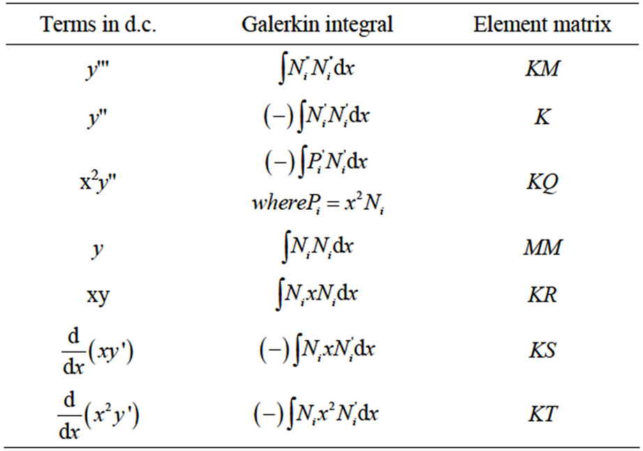
Table 1. From Smith [6] Discrete element matrix definitions.
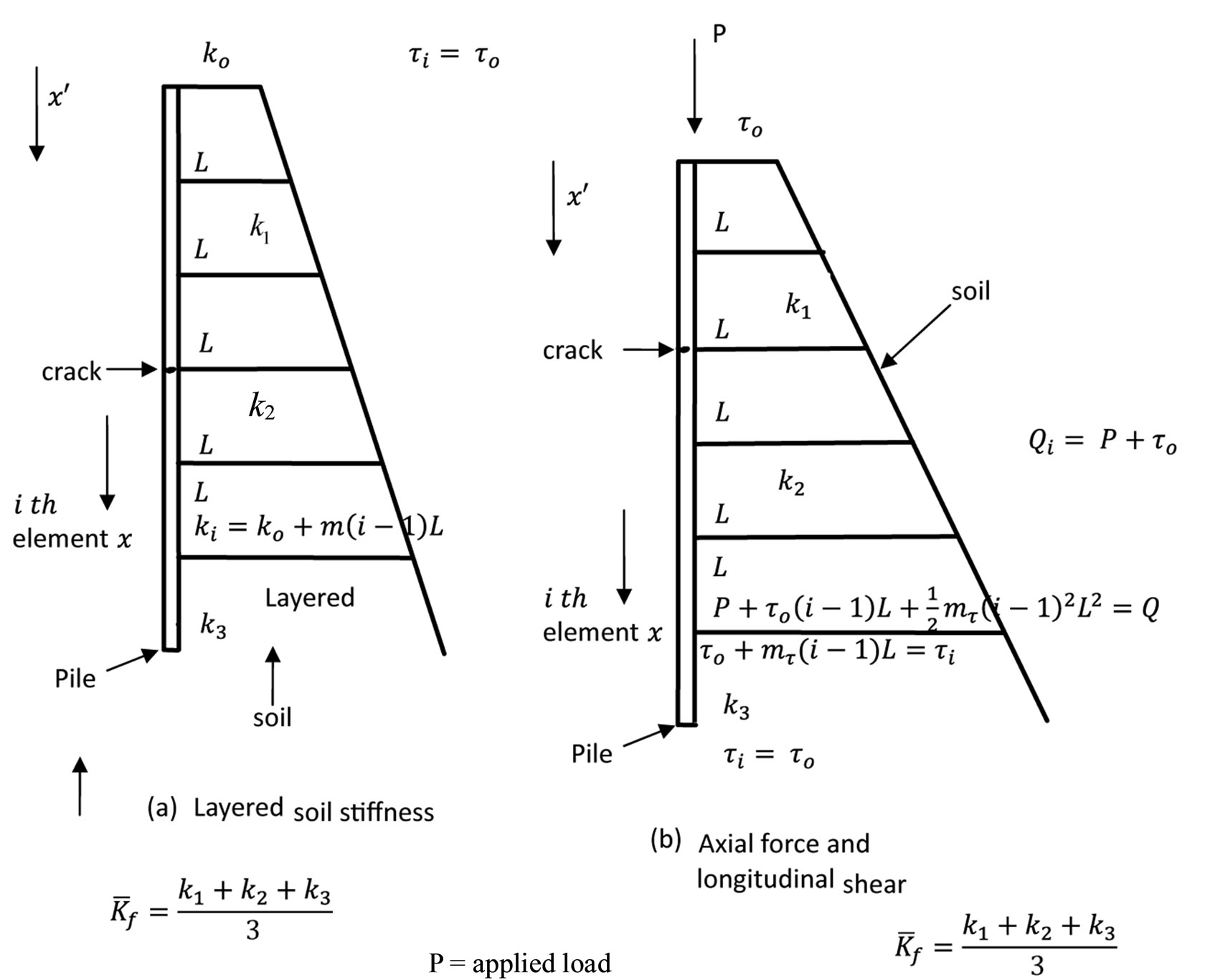
Figure 2. Distribu tion of soil resistances.
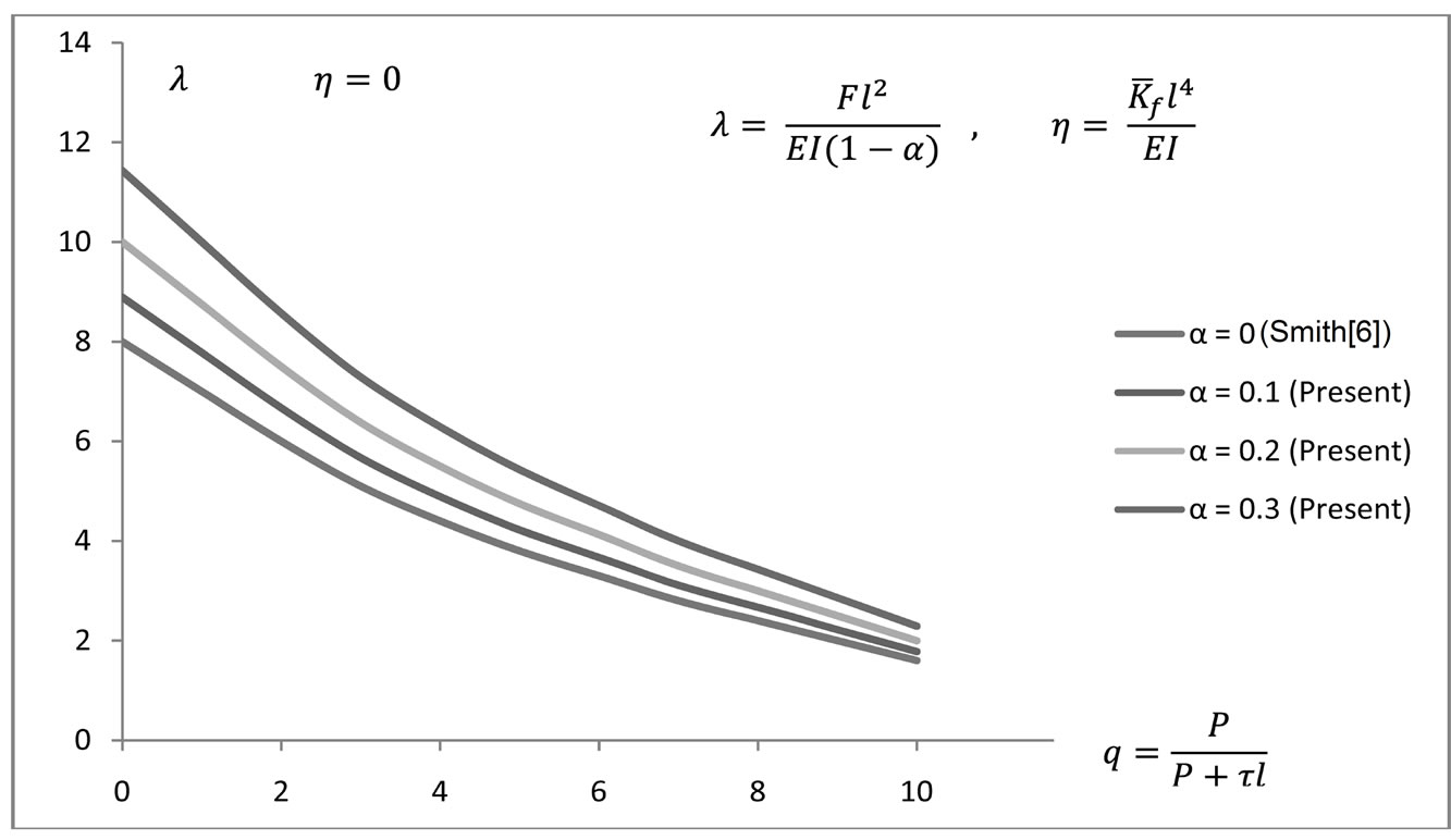
Figure 3. Effect of damage on pile buckling with zero soil modulus.

Figure 4. Effect of damage on pile buckling with 100% normalised soil modulus.
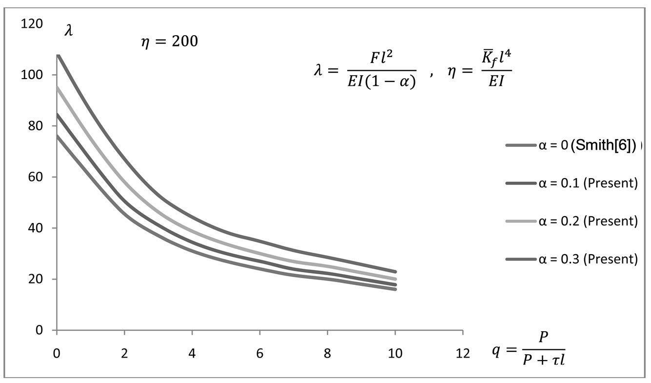
Figure 5. Effect of damage on pile buckling with 200% normalised soil modulus.
5. Conclusions
From the findings of the present study, we conclude as follows:
1) Pile damage due to an earthquake can be evaluated using a damage parameter which is calculated using fracture mechanics concepts.
2) The results of the present study show that when a pile is damaged, more soil resistance is needed to support the damaged pile. This finding is very helpful in a situation where the damaged pile cannot be replaced. In this case the soil or the ground is strengthened or mobilised to support the damaged pile.
3) Existing geotechnical methods of ground or soil improvements can be used to mobilise support for the damaged pile.
In layered soils, all or some of the weaker soil layers can be strengthened by the use of soil stabilization methods that currently exist.
REFERENCES
- I. M. Smith, “Transient Phenomena of Offshore Foundations,” In: O. C. Zienkiewicz, R. W. Lewis and K. G. Stagg, Eds., Numerical Methods in Offshore Engineering, John Wiley and Sons, London, 1978.
- I. W. Burgess, “The Stability of Slender Piles during Driving,” Geotechnique, Vol. 26, 1976, pp. 281-292. doi:10.1680/geot.1976.26.2.281
- I. W. Burgess, “Analytical Studies of Pile Wandering during Installation,” International Journal for Numerical and Analytical Methods in Geomechanics, Vol. 3, No. 1, 1979, pp. 49-62. doi:10.1002/nag.1610030106
- H. Leipholz, “Stability Theory,” Academic Press, New York, 1970.
- T. E. Smith and G. Herrmann, “Stability of a Beam on an Elastic Foundation Subjected to a Follower Force,” Journal of Applied Mechanics, Vol. 39, No. 2, 1972, pp. 628-629. doi:10.1115/1.3422743
- I. M. Smith, “Discrete Element Analysis of Pile Instability,” International Journal for Numerical and Analytical Methods in Geomechanics, Vol. 3, No. 1, 1979, pp. 205-211. doi:10.1002/nag.1610030208
- P. N. Jiki, “Buckling Analysis of Pre-Cracked BeamColumns by Liapunov’s Second Method,” European Journal of Mechanics A/Solids, Vol. 26, No. 3, 2007, pp. 503-518. doi:10.1016/j.euromechsol.2006.07.007
- N. Anifantis and A. D. Dimarogonas, “Stability Analysis of a Column with a Single Crack Subjected to Follower and Vertical Loads,” International Journal of Solids and Structures, Vol. 19, No. 4, 1983, pp. 281-291. doi:10.1016/0020-7683(83)90027-6
- D. Capuani and J. R. Willis, “Wave Propagation in Elastic Media with Cracks. Part 1. Transient Nonlinear Response of a Single Crack,” European Journal of Mechanics A/Solids, Vol. 16, 1997, pp. 377-408.
- S. P. Timoshenko and J. M. Gere, “Theory of Elastic Stability,” McGraw-Hill, New York, 1961.
- P. N. Jiki, J. U. Agber and N. N. Osadebe, “Finite Element Evaluation of Bearing Capacity Parameters for Soils in the University of Agriculture, Makurdi, Nigeria,” Indian Journal of Innovations and Development, Vol. 1, No. 3, 2012, pp. 121-126.
- V. V.Bolotin, “Nonconservative Problems of the Theory of Elasticity,” Pergamon Press, Oxford, 1963.
Appendix 1. Relevant Matrices from Smith [6].


NOTES
*Corresponding author.