Journal of Cosmetics, Dermatological Sciences and Applications
Vol.4 No.3(2014), Article ID:46388,6 pages DOI:10.4236/jcdsa.2014.43024
Nano-Patterning of Diffraction Gratings on Human Hair for Cosmetic Purposes
Khawar Abbas1, Drew F. Goettler1, Bruce C. Lamartine2, Zayd C. Leseman1
1Mechanical Engineering Department, University of New Mexico, Albuquerque, USA
2Los Alamos National Laboratory, Los Alamos, USA
Email: zleseman@unm.edu
Copyright © 2014 by authors and Scientific Research Publishing Inc.
This work is licensed under the Creative Commons Attribution International License (CC BY).
http://creativecommons.org/licenses/by/4.0/


Received 28 March 2014; revised 26 April 2014; accepted 2 May 2014
ABSTRACT
A method is presented for nano-patterning a diffraction grating on human hair with a focused ion beam. Strands of brown hair are patterned with hyperbolas and Archimedean spirals whose pitches range from 540 nm to 1040 nm. Exposure of the hair strands to white light at various incident angles demonstrates that light of varying wavelengths is diffracted by the diffraction gratings. The diffraction causes the brown strands of hair to reflect light from the entire range of visible light.
Keywords:Diffraction, Hair, Nanopatterning, Focused Ion Beam Milling

1. Introduction
The practice of hair dying for cosmetic purposes has been around for several hundred years. Temporary hair dyes are applied on hair to change its appearance hiding graying hair or to stay in line with the latest fashion trends. Greeks and Romans used naturally occurring henna as a temporary hair dye while Arab authors described application of the paste formed by the mixture of PbO and slaked lime (Ca(OH)2) in water on hair [1] . Presently there are numerous commercially available products that are used in highlighting hair strands for cosmetic purposes to brighten and/or create unnatural hair colors for Halloween, football games, etc.
Adverse effects of these synthetic hair dyes often range from skin discoloration and allergic irritations [2] to toxicity and cancer [3] [4] . In this paper we present a technique wherein nano-scale diffraction gratings are patterned on hair and could be used as an alternative to common hair dyeing treatments. Diffraction gratings do occur in nature for color generation [5] [6] and similar techniques are used in optics for color separation. We mimic and adapt nature’s color generation/separation technique to human hair as an alternative to chemical dyes. A Focused Ion Beam (FIB) was used to mill nano-scale diffraction gratings on individual strands of brown human hair in order to artificially add color to the hair strands through interference of light. Optical and SEM images were collected to qualitatively and quantitatively examine the effects of nano-patterning of the hair with the FIB (nanoFIBrication). Nano-scale Archimedean spirals and hyperbola patterns are the patterns chosen for this work. Though the technique of writing individual patterns on individual hair strands is not practical for commercial applications, nano-pattern transfer by large area direct embossing of the hair strands, or by a similar embossing of a polymer deposited on the hair, is feasible [7] . Large area nano-pattern embossing is easily accomplished and may ultimately become an alternative for hair and fiber coloration because of attractive complex patterns. Furthermore the present use and disposal of chemical dyes would be avoided.
2. Focused Ion Beam Milling
Incident light normal to a diffraction grating will produce a diffraction profile that is governed by the grating equation [8] .
 (1)
(1)
where a is the pitch of the diffraction grating, n is the nth bright fringe, θn is the angle corresponding to the nth slit, and λ is the wavelength of light incident on the grating. In order for the diffraction grating to work, the pitch of the grating must be on the order of the incident light. The wavelengths in the visible spectrum range between approximately 400 - 700 nm and is the range to be considered for coloring hair. Furthermore, light returned from a diffraction grating is usually directional.
Fabricating nanometer-sized patterns on a rough, curved surface of human hair in-situ is not a straightforward task. Most chip manufacturers easily create nanometer-sized patterns today, but the surface the pattern is created on is ideal—flat and smooth. Thus standard photolithographic techniques are not practical. For this work a Focused Ion Beam (FIB) is employed to fabricate nano-scale patterns onto individual hair strands. A FIB is a tool that allows for control of a beam of ions with nanometer precision—nanofabrication [9] . The FIB used in this work utilizes Ga+ ions. These are confined to a Gaussian current density distribution [10] [11] with a full-widthhalf-maximum (FWHM) beam diameter as small as 7 nm [12] . When the Ga+ ions reach the sample, atoms/ molecules from the sample’s surface are ejected, or sputtered away. By controlling the location of the ion beam, one can control the removal of material from the sample’s surface. In this work a Quanta Dual Beam 3D FEG™ scanning electron microscope by FEI was used to mill diffraction patterns on human hair. The Dual Beam system has the Ga+ ion source mounted 52˚ from vertical for milling and a scanning electron microscope (SEM) mounted vertically for imaging. Imaging with the SEM rather than FIB after milling ensures that no additional material is removed.
Human hair is not electrically conductive, so charge build-up must be overcome. If charge build-up occurs additional incoming ions will be deflected, thus creating two issues: First, milling requires many ions reach the same spot on the surface. If the incoming ions are deflected, then no milling will occur and no pattern can be generated. Second, charge build-up will distort any image taken with the SEM or FIB. Using a lower accelerating voltage, a reduced current, or a minimal beam dwell time on the SEM will minimize image distortions, but this also degrade image quality. In order to mitigate this issue, a thin layer of carbon was sputtered on to the hair. Depositing a thin (~10 nm) carbon layer to help dissipate charge on non-conducting samples is a common technique for SEM and TEM preparation [13] , and this same approach solved both issues.
Patterns were generated by a stream file [14] -[17] , which controls the location of the Gaussian Beam of ions. Each line in a stream file has three components; dwell time, x-position, and y-position. Dwell time determines the length of time the FIB is at a particular x-y coordinate and is also roughly proportional to the depth of the pattern at a constant acceleration potential of 30 kV in this work. The beam’s diameter is dictated by its current, which varies depending on the requirements of the pattern. Both x and y coordinates correspond to pixels on the screen and the coordinates do not correspond to an absolute dimension.
A given pattern’s x-y dimensions, as defined by the stream file, are scaled to the horizontal field width (HFW) specified in the system. For the system used in this work there are 4096 pixels in the horizontal-direction (x-direction). If the HFW = 100 μm, then the spacing between each pixel is 24.4 nm. Similarly, changing the HFW to 150 μm creates 36.6 nm spacing etc. So if the spacing between two mill points is only 10 pixels, the actual spacing could either be 244 nm or 366 nm. All of the stream files used for generating ion beam patterns were calculated and stored using MathCAD routines. All scalar inputs could be declared prior to runtime thus parameterizing any pattern for varying HFWs. In addition all patterns were milled with equal arc-length step segments [18] so that the variation in groove’s depth with beam position was minimized.
Two different diffraction patterns were used for this work: an Archimedean spiral and a hyperbola. The Archimedean spiral, Figure 1, was created with a 30 kV, 1 nA ion beam (44 nm beam diameter at FWHM), and a 3 μs dwell time per pixel. By cycling through the pattern 1000 times, a mill depth greater than 800 nm was achieved. Two different spiral pitches of 730 nm, and 540 nm were milled using two separate HFWs.
The second pattern, a hyperbola, is shown in Figure 2. It was milled at 30 kV, 300 pA current (31 nm beam diameter at FWHM), and a 1 μs dwell time per pixel. Cycling through the pattern 3000 times resulted in a mill depth of approximately 800 nm. Two different HFWs created hyperbolas with pitches of 1040 nm, and 840 nm.
3. Optical Observations
An optical microscope was used to image and observe the diffraction changes on the hair specimen. The illumination light (perpendicular incidence) of the microscope was not utilized for these micrographs. Instead an external light source was utilizewd at an oblique angle. The light source used was a halogen bulb without filters. By changing the angle of this incident illumination from the side the changes in the diffracted wavelengths were observed.

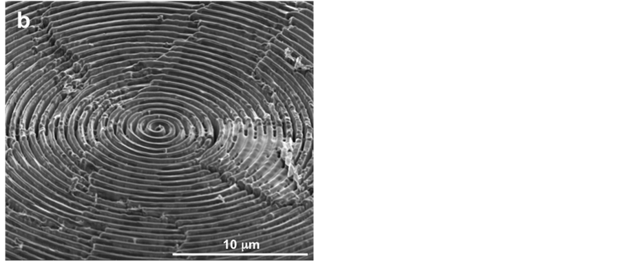
Figure 1. Archimedean spiral pattern milled on a strand of brown hair. (a) Overview of entire spiral pattern viewed at an angle of 52˚; (b) Center portion of spiral pattern viewed at an angle of 52˚. The pitch is 730 nm.
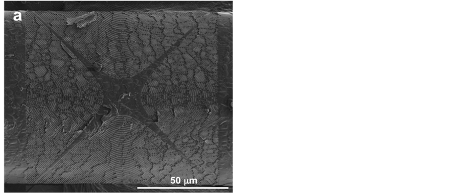
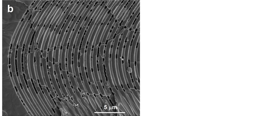
Figure 2. Hyperbola pattern milled on strand of brown hair. (a) Overview of entire hyperbola pattern; (b) Center portion of hyperbola pattern. The pitch is 1040 nm.
Figures 3(a)-3(d) show the same two hair strands which have been patterned with the Archimedean spirals (top strand) and hyperbola (bottom strand) diffraction gratings. Three Archimedean spirals are patterned on the top strand. From left to right their pitches are 730 nm, 730 nm, and 540 nm. Two hyperbola patterns are patterned on the bottom hair strand. The left hyperbola has a 1040 pitch and the right hand hyperbola has an 840
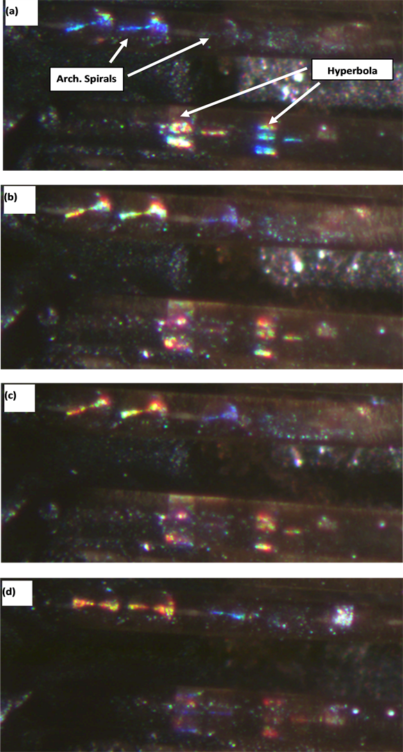
Figure 3. Light diffraction from nanoFIBricated patterns at various azimuth angles of incident light. (a) 10˚; (b) 20˚; (c) 30˚; (d) 40˚. The pitches on the spirals (left to right) located on the second strand of hair from the top are 730 nm, 730 nm, and 540 nm. The pitches on the hyperbola patterns (left to right) located on the third strand of hair from the top are 1040 nm and 840 nm.
nm pitch. Each successive subfigure in Figure 3 is the same with the exception that the azimuth angle for the incident light has been rotated in increments of 10˚. Specifically, Figure 3(a) is for an azimuth of 10˚, Figure 3(b) is for an azimuth of 20˚, etc.
The diffracted wavelengths are the function of the pattern type, pitch of the pattern and angle of the incident light. Figure 3 shows the transition of the diffracted light on the machined patterns from deep blue hue (Figure 3(a)) on Archimedean spiral patterns at the top left corners of the images at 10˚ azimuth angle of the incident light to green yellow (Figure 3(b) azimuth 20˚) to yellow-orange (Figure 3(c) azimuth 30˚) to finally orangered (Figure 3(d) azimuth 40˚).
Similarly changes in the diffracted light are also visible on the hyperbola patterns. For example, the hyperbola patterns in Figure 3(d) show colors spanning the entire visible spectrum from violet to red. It may also be noted that pitch of the pattern also has an effect on the diffracted patterns. This effect is more pronounced on the hyperbola pattern than on the spiral pattern especially at low azimuthal angles.
4. Summary and Conclusion
This work successfully demonstrated the use of nano-scale patterning on human hair for cosmetic purposes. By use of this technique complex patterns could be easily created on human hair to artificially color the hair. Archimedean spirals and hyperbola diffraction patterns with pitches varying from 540 nm - 1040 nm were patterned in this work. Observations of the hair fibers with an optical microscope demonstrated that the diffractions gratings returned light from brown hair that spanned the full color spectrum.
Acknowledgements
The authors will like to acknowledge the support of Center of Micro-Engineered Materials at the University of New Mexico for this work.
References
- Walter, P., Welcomme, E., Hallégot, P., Zaluzec, N.J., Deeb, C., Castaing, J., Veyssière, P., Bréniaux, R., Lévêque, J.-L. and Tsoucaris, G. (2006) Early Use of Pbs Nanotechnology for an Ancient Hair Dyeing Formula. Nano Letters, 6, 2215-2219. http://dx.doi.org/10.1021/nl061493u
- Swift, J.A. and Brown, A.C. (1972) The Critical Determination of Fine Changes in the Surface Architecture of Human Hair Due to Cosmetic Treatment. Journal of the Society of Cosmetic Chemists, 23, 695-670.
- Nohyneka, G.J., Fautzb, R., Benech-Kiefferc, F. and Toutaina, H. (2004) Review: Toxicity and Human Health Risk of Hair Dyes. Food and Chemical Toxicology, 42, 517-543. http://dx.doi.org/10.1016/j.fct.2003.11.003
- Thun, M.J., Altekruse, S.F., Namboodiri, M.M., Calle, E.E., Myers, D.G. and Heath, C.W. (1994) Hair Dye Use and Risk of Fatal Cancers in U.S. Women. Journal of the National Cancer Institute, 86, 164-165. http://dx.doi.org/10.1093/jnci/86.3.210
- Sun, C.-H., Jiang, P. and Jiang, B. (2008) Broadband Moth-Eye Antireflection Coatings on Silicon. Applied Physics Letters, 92, Article ID: 061112.
- Wilson, S.J. and Hutley, M.C. (1982) The Optical Properties of “Moth Eye” Antireflection Surfaces. Journal of Modern Optics, 29, 993-1009.
- Lamartine, B.C. and Orler, E.B. (2011) Hair Treatment Process Providing Dispersed Colors by Light Diffraction. Los Alamos National Laboratory Patent.
- Hecht, E. (2002) Optics. 4th Edition.
- Goettler, D.F., Su, M.F., Reinke, C.M., Alaie, S., Hopkins, P.E., Olsson, R.H.I., El-Kady, I. and Leseman, Z.C. (2011) Realization of a 33 GHz Phononic Crystal Fabricated in a Freestanding Membrane. AIP Advances, 1, Article ID: 042001.
- Edinger, K. and Kraus, T. (2001) Modeling of Focused Ion Beam Induced Chemistry and Comparison with Experimental Data. Microelectronic Engineering, 57-58, 263-268. http://dx.doi.org/10.1016/S0167-9317(01)00487-7
- Nassar, R., Vasile, M. and Zhang, W. (1998) Mathematical Modeling of Focused Ion Beam Microfabrication. Journal of Vacuum Science & Technology B, 16, 109-115. http://dx.doi.org/10.1116/1.589763
- (2007) Quanta 3D FEG Datasheet. FEI Company.
- Giannuzzi, L.A. and Stevie, F.A. (1999) A Review of Focused Ion Beam Milling Techniques for Tem Specimen Preparation. Micron, 30, 197-204. http://dx.doi.org/10.1016/S0968-4328(99)00005-0
- Lamartine, B.C. (2003) Reflective Diffraction Grating. US 6583933.
- Lamartine, B.C. and Stutz, R.A. (1995) Ultrahigh Vacuum Focused Ion Beam Micromill and Articles Therefrom. US 5721687.
- Lamartine, B.C. and Stutz, R.A. (1998) Focused Ion Beam Milling and Article Therefrom. US 5773116.
- Lamartine, B.C. Direction Aggregate Element Diffraction Patent (daedp). Pending.
- Lamartine, B.C. (2010) Angarclen1.Xmcd, an Unpublished MathCAD Program.