Journal of Applied Mathematics and Physics
Vol.04 No.08(2016), Article ID:69752,13 pages
10.4236/jamp.2016.48163
Boundary Element Analysis of Two Dimensional Structure Water Entry Based on Attached Water Quality
L. Zou1,2, Z. Zong1,2*, S. Feng3, G. X. Zhu1,2, G. P. Yu1,2
1State Key Laboratory of Structural Analysis for Industrial Equipment, Dalian, China
2Collaborative Innovation Center for Advanced Ship and Deep-Sea Exploration (CISSE), Shanghai, China
3Dalian COSCO KHI Ship Engineering Co. Ltd., Dalian, China


Received 24 April 2016; accepted 8 August 2016; published 15 August 2016

ABSTRACT
Combining nonlinear boundary conditions of free liquid surface, the impact force of wedge shape profile and the change of free liquid surface were calculated and analyzed based on the solving ideas of Von Karman T. The results were compared with the results of the existing literature, and the results were in good agreement with the existing results. In addition, the impact forces of U profile and the external drift profile were calculated, and the impact load of two kinds of profiles were analyzed through time evolution.
Keywords:
Water Entry, Attached Water Quality

1. Introduction
The water entry problem of structure was the strong nonlinear interaction between the structure surface and the free liquid surface. The water entry problem of structure was widely used in the field of vessel and marine engineering. From the end of the last century, the problem of landing on water was studied by von Karman [1], the structure water entry problems which were studied lasted for nearly a hundred years. But until now, the structure entry water problems have been still concerned by every national researcher. At present, the water entry problem is mainly confined to studies of the two-dimensional level. In the practical application, the three dimensional problem was usually transformed to a two dimensional problem by using slice method.
In the experimental studies, wedge shape was experimented from the bottom lift angle 1˚ to 15˚ by Chuang S L, the peak value of impact pressure was measured in the water entry process. And the regression formula between the peak value of impact pressure and bottom lift angle was given [2]. The change of free liquid surface and the movement of structure were tested by Greenhow M in the water entry process of wedge shape and cylinder, and the numerical method was used to calculate [3]-[5]. The wedge shape was tested at bottom lift angle 30˚ by Zhao R and Faltinsen O, velocity, impact fore and the fixed point pressure of surface were measured in the water entry process. The experimental results were compared with the numerical results [6]. It verified the correctness of the numerical method. The movement, stress, and movement of the free liquid surface were studied in water entry process of cylinder by Colicchio G, the speed sensor was used to measure the water entry velocity, and the measurement velocity was taken as the initial condition for the numerical calculation [7].
Numerical method was widely used in the calculation of structure water entry. Aimed at the problem of aircraft landing on the water, the conservation of momentum theorem was applied to calculate the impact force and the average pressure of structure by von Karman T. Due to neglect many important factors, the calculation results were relatively small, and there were many limitations in the application. Subsequently, the free liquid surface motion was considered to improve the calculation of wet half width on the basis of von Karman T, and the distribution of impact pressure on the surface was calculated [8]. The calculation results of Wagner H were relatively large, but because of the simple calculation theory and the results were helpful to the structural design of the security. Until now, the Wagner H’s theory is still used by many people to estimate the impact load. Combining with the nonlinear boundary conditions of the free liquid surface, two dimensional boundary element methods were used to simulate the water entry process of wedge shape, so that the calculation could be carried out smoothly [9]. Based on the theory of Wagner H, the asymptotic matching method was used to calculate the impact problem of two dimensional structure by Watanaber I [10], the peak pressure of impact pressure was in good agreement with the Wagner H’s. Based on the test of flat panel impact, the calculation model which used one dimensional movement to simulate the air movement between the flat panel and the surface was proposed [11].
In this paper, the characteristics of movement, pressure distribution and impact force on free liquid surface were studied in the water entry process. First, the impact force solution idea of Karman T von was introduced. Secondly, the calculation theory of free liquid surface movement based on the Lagrange grid was described. The last, the free liquid surface movement, pressure distribution and the variation of the impact force for wedge profile, U profile and external drift profile were calculated and compared between each other.
2. Problem Formulation
As shown in Figure 1, computation tank which length was  and height is
 , the initial velocity potential of free liquid surface was zero. The coordinate origin was located at the midpoint of the free liquid surface, X axis was horizontal to the right, Y axis was perpendicular to the top, water entry profile was a constant speed V = 1 m/s along the Y axis into the water.

Figure 1. Calculation model of water entry.
To reduce the number of units and improve the calculation efficiency, the calculation tank and water entry profile were divided into two parts along Y. The model was gotten as Figure 2.
Three typical water entry profiles were calculated in this paper. For Figure 3, they were respectively wedge profile which bottom lift angle was , U profile and external drift profile.
3. The Theory of Computation
3.1. Governing Equations
In this paper, according to the impulse theory of von Karman and combing with the solution method of the attached water quality, the water entry problem of the two dimensional structure was solved. From Figure 4, the

Figure 2. Calculation model of water entry after segmentation.

Figure 3. Three types of model for water entry analysis.

Figure 4. Impact model of von Karman.
impact force calculation idea of von Karman T was as follows: assuming the water entry body was a wedge profile which enters the water at a constant speed and the bottom lift angle was , the depth of water entry is y, the wet half width was c, and assume the velocity potential was
 , when the free surface was in the water entry process and no displacement. The body impact force could be obtained by Formula (1):
 (1)
(1)
In Formula (1), F is impact force, V was velocity of body water entry, y was body water entry part which was relative static water depth,  was vertical attached water quality of body for different water depths. So it was very important to solve attached water quality. According to calculation theory of von Karman T, the attached water quality for wedge profile was [1]:
 (2)
(2)
Joined the Formula (2) to Formula (1), the dimensionless form of impact force was:
 (3)
(3)
 was impact force coefficient. According to von Karman T theory, the numerical results were in good agreement with the experimental results on wedge profile, when
  was bigger. But there were many limitations in the application. First, the model was confined to the wedge. Secondly, the change of free liquid surface was not considered in calculation.
3.2. The Discrete Governing Equations
The basic ideas of Boundary Element Method is that the boundary discrete into several elements. In this method, boundary condition can be transformed into the boundary of each element. Then, the integral equations can be calculated by the summation of each element
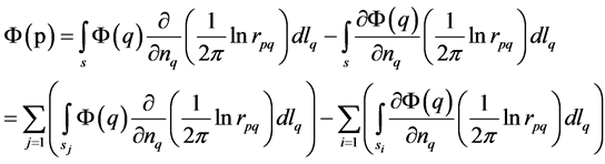 (4)
(4)
where  is the distance between point
  and
and .
.
In this work, the linear boundary element is used to disperse the field. Finally, the governing equations can be regarded as

where ,
,  ,
,  is the coefficient matrix,
  is the unit matri.
3.3. The Coefficient Matrix
In our work, the integral equations can be calculated by transforming the coordinate of elements. Firstly, the midpoint of elements can be regarded as the origin of local coordinate. The x axis is the direction along the border. And the y axis is the vertical direction on elements, pointing to the internal area, as shown in Figure 5. After, the coordinate is shown in Figure 6.
In the coefficient matrix,  denotes the influence of velocity potential resulting from double unit.
  denotes the influence of velocity potential resulting from unit sink. They can be obtained as following equations

Figure 5. The j th boundary element and the ith boundary element before coordinate transforming.

Figure 6. Node qj, node qj+1 and node pi after coordinate transforming.

where A, B, C, D can be calculated as


Specially,  may be a singularity. At this moment,
  should find limit

3.4. Boundary Condition
Boundary conditions were shown in Figure 7. Body surface met the conditions of non-penetration. Boundary conditions taken , the bottom of tank and the side wall was satisfied with the non-penetrating condition.
Free surface was given the first kind of boundary condition, its velocity potential could be calculated according to the water entry process about the time iteration by Formula (8).
3.5. Free Surface Treatment
Free surface satisfied kinematic equation
 (4)
(4)
In addition, the free liquid surface also satisfied the Lagrange integral:
 (5)
(5)
 was atmosphere pressure. Joined
  to Formula (5), get [9]:
 (6)
(6)
Sun pointed out that the gravity was small proportion in the impact process [12]. So the effect of gravity was ignored. If g = 0, there was:
 (7)
(7)
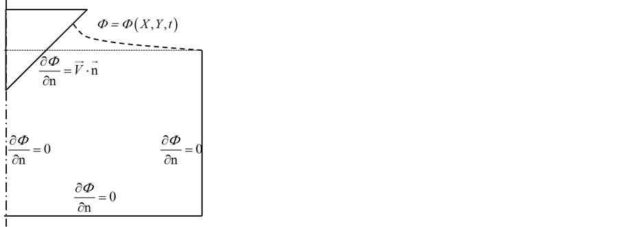
Figure 7. Boundary condition for water entry problem.
In this paper, the free surface used Lagrange grid. For Figure 8, supposed that the velocity potential and speed of point on the free surface were calculated at current moment t, given time step , the coordinates of the next moment t + dt were calculated at this point by Formula (4), and the velocity potential of next moment could be calculated by Formula (7):
 (8)
(8)
4. The Calculation Results
4.1. Wedge Water Entry
Free surface deformation
Taken the wedge shape with the bottom lift angle as 10 degrees as an example, All time free surface motion was calculated and the results were shown in Figure 9.
The free liquid surface motion results of non-dimensionless were given by Zhao R [9]. The free surface shape is compared with the results of Zhao Rat t = 0.107 s moment. The results were shown in Figure 10.
In Figure 10, V represented the speed of the water. t represented the water entry time from the bottom of profile to contact surface. It could be seen from Figure 10 that the deformation calculation of the free surface was in good agreement with the results of Zhao R.

Figure 8. The displacement and velocity potential change of each node on the free surface.

Figure 9. The motion of the free surface.
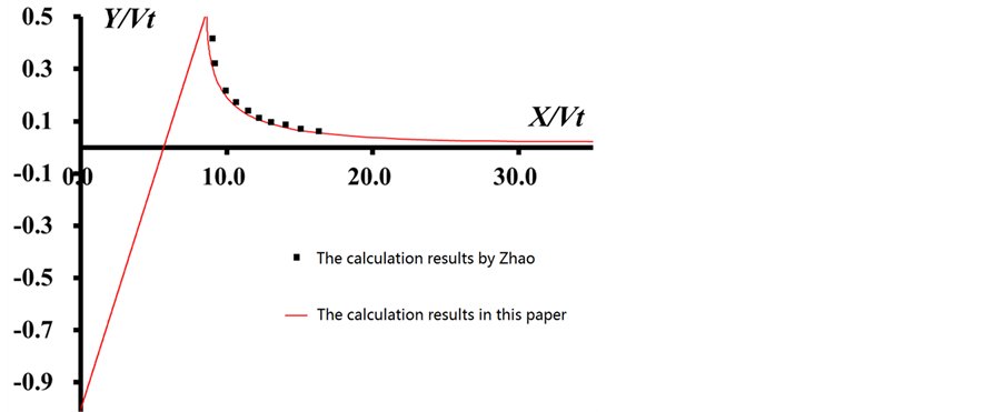
Figure 10. Comparison of the free surface’s motion.

Figure 11. Pressure on the body.
Pressure distribution
The surface pressure could be calculated by Formula (9) [13]
 (9)
(9)
Taken 10 degree wedge shape as an example, the pressure distribution on the surface in the water entry process was shown in Figure 11.
In Figure 11, P0 represented atmosphere pressure. The pressure was the largest near intersection of body surface and free liquid surface at a certain moment. For a point on the body surface, when the free liquid surface reached this point, this pressure quickly became large. Then as time goes by, the pressure of this point gradually became small and gone stable finally. And all the points on the wedge body were all the final approximation
 .
.
Impact force
Taken the wedge shape with the bottom lift angle as 10 degrees as an example, the change of attached water quality in water entry process and the impact force was calculated by Formula (1). The results were shown as Figure 12 and Figure 13. In figure, the horizontal coordinates represented the depth of the water entry.
From Figure 14, the relationship between the impact force of 10˚ wedge shape and water entry depth was approximately linear. The impact force coefficient  was obtained by Linear fitting between the impact force and the water entry. For the wedge shape, the coefficient of impact force was related to the bottom lift angle. The results of the impact force coefficient were shown in Figure 15.

Figure 12. Dependence of added mass on the entry depth.

Figure 13. Impact force related to the depth of water entry.

Figure 14. The results of the impact force coefficient.
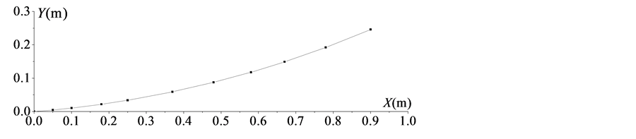
Figure 15. The U profile.
Form Figure 14, the numerical results were in good agreement with the calculation results of Zhao R [9]. When the bottom lift angle was relatively small, von Karman T did not consider the shape change of free liquid surface, therefore the calculation coefficient of impact force was small [1]. With the bigger bottom lift angle, the relative error between the calculation coefficient of impact force and von Karman T’s was gradually reduced. When the bottom lift angle was bigger, it showed that the velocity potential of free liquid surface and deformation were smaller, and had little effect on the impact force.
4.2. U-Shaped Section Waterentry
The curve of the U-shaped section was selected as Figure 15.
Similar to the wedge shape, the free surface movement, pressure distribution and the impact force of the U-shaped section in the water entry process were shown as Figure 16.
Pressure distribution curves of different time were shown as Figure 17. Compared with the wedge, the pressure peak of the U profile was still located near the intersection of the free liquid surface and body surface at every moment. The pressure distribution of other body surfaces was more stable, but the pressure peak decreased with time, and the stationary value gradually decreased. This showed that the initial impact load of the U shaped profile was larger, and reduced later.

Figure 16. The motion of the free surface for the U shape body.

Figure 17. The pressure on the U shape body.
As was shown in Figure 18, the impact force of U profile became larger with the increasing water entry depth, but the change rate of y was slower and slower. It showed that the impact force gradually tended to be flat over time.
4.3. Flared Section Waterentry
The curve of flared section surface was shown in Figure 19.
The free liquid surface movement, pressure distribution and the impact force of external drift surface were as Figure 20.
As was shown in Figure 21, compared with U profile, the characteristics of pressure distribution on flared section was obviously different. The peak value of impact load of U shape was in the initial moment of the water

Figure 18. The impact force of the U shape body.

Figure 19. The flare body.

Figure 20. The motion of the free surface for the flare body.

Figure 21. The pressure on the flare body.

Figure 22. The impact force of the flare body.
entry. The pressure peak and pressure steady value of external drift profile gradually became large. It indicated that the impact load increased with the process passage of the water entry. For Figure 22, the impact force became bigger with the increasing water entry depth, which indicated that the action load of the fluid on the structure was increasing.
5. Conclusions
In this paper, three typical profiles are selected. The free liquid surface movement, the impact pressure distribution and the impact force are calculated in the water entry process. Based on the results of the three surfaces, the main conclusions are as follows:
1) When three typical profiles go into water, the free liquid surface happen movement, and the pressure near the intersection of the free liquid surface and body surface is far greater than the pressure value of other body surfaces.
2) For impact pressure, the pressure peak value of wedge shape doesn’t change much at different times, and steady value is basically unchanged; the pressure peak value of U shaped section becomes small, and the stationary value also becomes small; the pressure peak value of external drift profile becomes large and the stationary value also becomes large.
3) The impact force of three surfaces becomes larger with the increasing water entry depth. The relationship between the impact of wedge shape and water entry depth is approximately linear. The impact force of U shaped profile becomes smaller with the increasing time. The impact force of external drift profile increases quickly with the increasing time.
Acknowledgements
This research is funded by National Natural Science Foundation of China (51379033; 51379030; 51239002; 51221961), Special funds for basic scientific research business of Central University (DUT15LK43, DUT15LK32) and 973 Project (2013CB036101).
Cite this paper
L. Zou,Z. Zong,S. Feng,G. X. Zhu,G. P. Yu, (2016) Boundary Element Analysis of Two Dimensional Structure Water Entry Based on Attached Water Quality. Journal of Applied Mathematics and Physics,04,1533-1545. doi: 10.4236/jamp.2016.48163
References
- 1. von Karman, T. (1929) The Impact on Seaplane Floats during Landing. National Advisory Committee for Aeronatics, 321, 309-313.
- 2. Chuang, S.L. (1967) Experiments on Slamming of Wedge-Shaped Bodies. Journal of Ship Research, 11, 190-198.
- 3. Greenhow, M. and Lin, W.M. (1983) Nonlinear-Free Surface Effects: Experiments and Theory. Massachusetts Inst of Tech Cambridge Dept of Ocean Engineering.
- 4. Greenhow, M. and Moyo, S. (1997) Water Entry and Exit of Horizontal Circular Cylinders. Philosophical Transactions of the Royal Society of London. Series A: Mathematical, Physical and Engineering Sciences, 355, 551-563.
- 5. Greenhow, M. (1987) Wedge Entry into Initially Calm Water. Applied Ocean Research, 9, 214-223. http://dx.doi.org/10.1016/0141-1187(87)90003-4
- 6. Zhao, R., Faltinsen, O. and Aarsnes, J. (1996) Water Entry of Arbitrary Two-Dimensional Sections with and without Flow Separation. Proceedings of the 21st Symposium on Naval Hydrodynamics, National Academy Press, Washington DC, 408-423.
- 7. Sun, H. (2007) A Boundary Element Method Applied to Strongly Nonlinear Wave-Body Interaction Problems. Norwegian University of Science and Technology.
- 8. Wagner, H. (1932) Uber Stoss-und Gleitvorgange an der Oberflache von Flussigkeiten. Z. Angew. Math. Mech., 12, 193-215. http://dx.doi.org/10.1002/zamm.19320120402
- 9. Zhao, R. and Faltinsen, O. (1993) Water Entry of Two-Dimensional Bodies. Journal of Fluid Mechanics, 246, 593-612. http://dx.doi.org/10.1017/S002211209300028X
- 10. Watanabe, I. (1986) Analytical Expression of Hydrodynamic Impact Pressure by Matched Asymptotic Expansion Technique. The Japan Society of Naval Architects and Ocean Engineers, 71, 77-85.
- 11. Verhagen, J.H.G. (1967) The Impact of a Flat Plate on a Water Surface. Journal of Ship Research, 11, 211-223.
- 12. Sun, H. (2007) A Boundary Element Method Applied to Strongly Nonlinear Wave-Body Interaction Problems. Norwegian University of Science and Technology.
- 13. Lu, C. and He, Y. (1997) Ship Hull Slamming Analysis with Nonlinear Boundary Element Method. China Ocean Engineering, 11, 411-418.
NOTES

*Corresponding author.