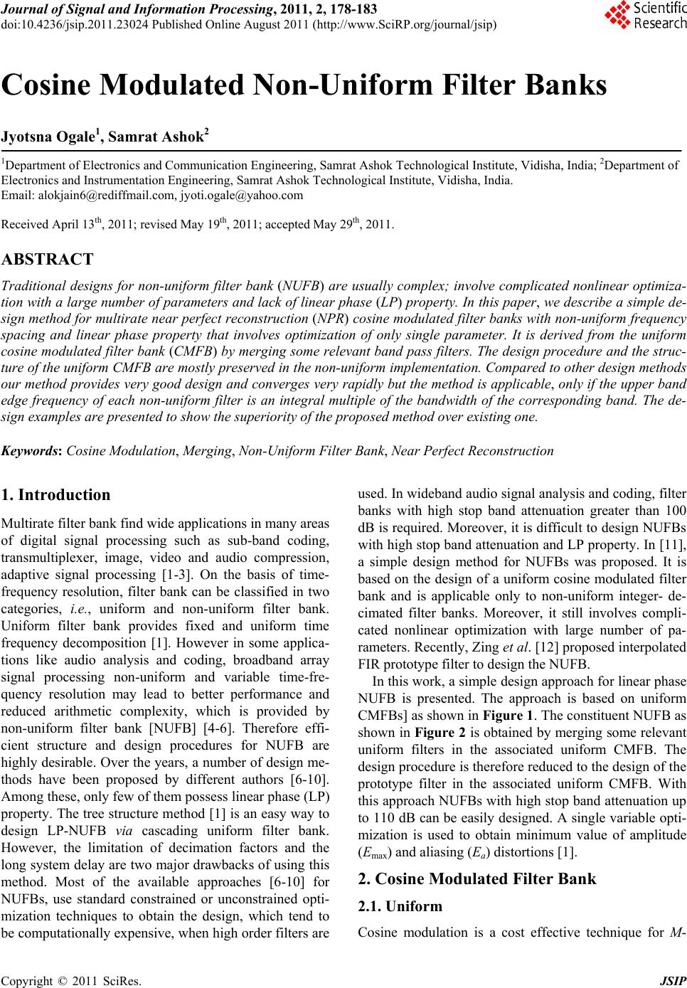
 Journal of Signal and Information Processing, 2011, 2, 178-183 doi:10.4236/jsip.2011.23024 Published Online August 2011 (http://www.SciRP.org/journal/jsip) Copyright © 2011 SciRes. JSIP Cosine Modulated Non-Uniform Filter Banks Jyotsna Ogale1, Samrat Ashok2 1Department of Electronics and Communication Engineering, Samrat Ashok Technological Institute, Vidisha, India; 2Department of Electronics and Instrumentation Engineering, Samrat Ashok Technological Institute, Vidisha, India. Email: alokjain6@rediffmail.com, jyoti.ogale@yahoo.com Received April 13th, 2011; revised May 19th, 2011; accepted May 29th, 2011. ABSTRACT Traditional designs for non-uniform filter bank (NUFB) are usually complex; involve complicated nonlinear optimiza- tion with a large number of parameters and lack of linear phase (LP) property. In this paper, we describe a simple de- sign method for multirate near perfect reconstruction (NPR) cosine modulated filter banks with non-uniform frequency spacing and linear phase property that involves optimization of only single parameter. It is derived from the uniform cosine modulated filter bank (CMFB) by merging some relevant band pass filters. The design procedure and the struc- ture of the uniform CMFB are mostly preserved in the non-uniform implementation. Compared to other design methods our method provides very good design and converges very rapidly but the method is applicable, only if the upper band edge frequency of each non-uniform filter is an integral multiple of the bandwidth of the corresponding band. The de- sign examples are presented to show the superiority of the proposed method over existing one. Keywords: Cosine Modulation, Merging, Non-Uniform Filter Bank, Near Perfect Reconstruction 1. Introduction Multirate filter bank find wide applications in many areas of digital signal processing such as sub-band coding, transmultiplexer, image, video and audio compression, adaptive signal processing [1-3]. On the basis of time- frequency resolution, filter bank can be classified in two categories, i.e., uniform and non-uniform filter bank. Uniform filter bank provides fixed and uniform time frequency decomposition [1]. However in some applica- tions like audio analysis and coding, broadband array signal processing non-uniform and variable time-fre- quency resolution may lead to better performance and reduced arithmetic complexity, which is provided by non-uniform filter bank [NUFB] [4-6]. Therefore effi- cient structure and design procedures for NUFB are highly desirable. Over the years, a number of design me- thods have been proposed by different authors [6-10]. Among these, only few of them possess linear phase (LP) property. The tree structure method [1] is an easy way to design LP-NUFB via cascading uniform filter bank. However, the limitation of decimation factors and the long system delay are two major drawbacks of using this method. Most of the available approaches [6-10] for NUFBs, use standard constrained or unconstrained opti- mization techniques to obtain the design, which tend to be computationally expensive, when high order filters are used. In wideband audio signal analysis and coding, filter banks with high stop band attenuation greater than 100 dB is required. Moreover, it is difficult to design NUFBs with high stop band attenuation and LP property. In [11], a simple design method for NUFBs was proposed. It is based on the design of a uniform cosine modulated filter bank and is applicable only to non-uniform integer- de- cimated filter banks. Moreover, it still involves compli- cated nonlinear optimization with large number of pa- rameters. Recently, Zing et al. [12] proposed interpolated FIR prototype filter to design the NUFB. In this work, a simple design approach for linear phase NUFB is presented. The approach is based on uniform CMFBs] as shown in Figure 1. The constituent NUFB as shown in Figure 2 is obtained by merging some relevant uniform filters in the associated uniform CMFB. The design procedure is therefore reduced to the design of the prototype filter in the associated uniform CMFB. With this approach NUFBs with high stop band attenuation up to 110 dB can be easily designed. A single variable opti- mization is used to obtain minimum value of amplitude (Emax) and aliasing (Ea) distortions [1]. 2. Cosine Modulated Filter Bank 2.1. Uniform Cosine modulation is a cost effective technique for M- 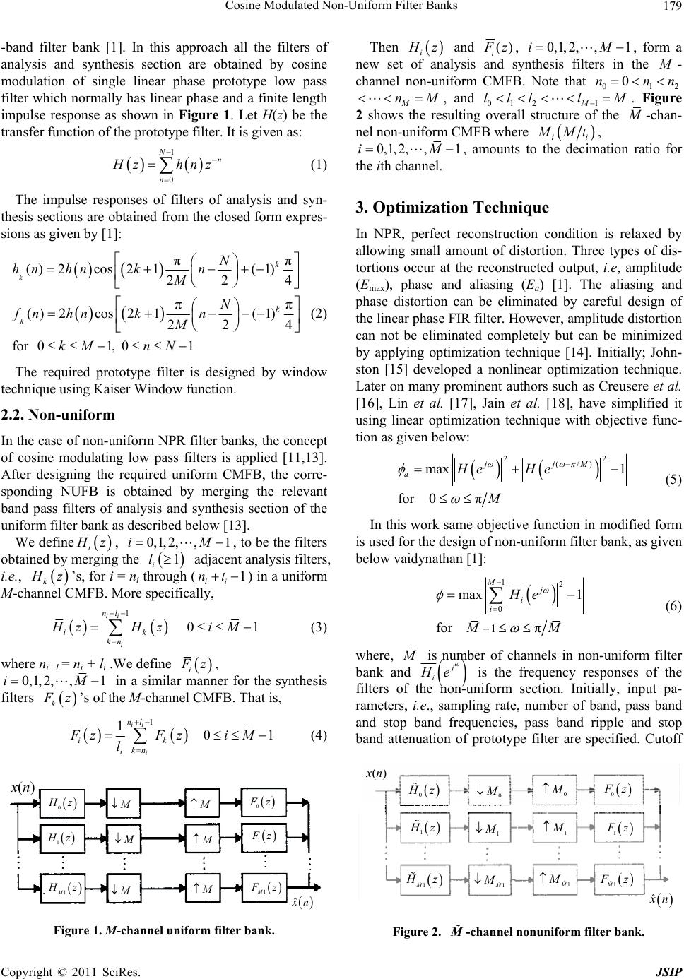 Cosine Modulated Non-Uniform Filter Banks179 -band filter bank [1]. In this approach all the filters of analysis and synthesis section are obtained by cosine modulation of single linear phase prototype low pass filter which normally has linear phase and a finite length impulse response as shown in Figure 1. Let H(z) be the transfer function of the prototype filter. It is given as: 1 0 Nn n zhnz (1) The impulse responses of filters of analysis and syn- thesis sections are obtained from the closed form expres- sions as given by [1]: π ()2cos 21(1) 22 π ()2cos 21(1) 22 for 01, 01 k k k k N hn hnkn M N fn hnkn M kM nN π 4 π 4 (2) The required prototype filter is designed by window technique using Kaiser Window function. 2.2. Non-uniform In the case of non-uniform NPR filter banks, the concept of cosine modulating low pass filters is applied [11,13]. After designing the required uniform CMFB, the corre- sponding NUFB is obtained by merging the relevant band pass filters of analysis and synthesis section of the uniform filter bank as described below [13]. We define i z, 0,1, 2,,1iM, to be the filters obtained by merging the adjacent analysis filters, i.e., 1 i l k z’s, for i = ni through () in a uniform M-channel CMFB. More specifically, 1 ii ln 1 01 ii i nl ik kn HzH zi M (3) where ni+1 = ni + li .We define i z, 0,1, 2,,1iM in a similar manner for the synthesis filters k z’s of the M-channel CMFB. That is, 1 1 01 ii i nl ik kn i FzF ziM l (4) (n) 0 z 0 z 1 z 1M z 1 z 1M z ˆ n Figure 1. M-channel uniform filter bank. Then i z and () i z, 0,1,2,,1iM, form a new set of analysis and synthesis filters in the - channel non-uniform CMFB. Note that 2 M 01 0nn n nM , and 012 1M llll M . Figure 2 shows the resulting overall structure of the -chan- nel non-uniform CMFB where ii lMM , 0,1, 2,,1iM , amounts to the decimation ratio for the ith channel. 3. Optimization Technique In NPR, perfect reconstruction condition is relaxed by allowing small amount of distortion. Three types of dis- tortions occur at the reconstructed output, i.e, amplitude (Emax), phase and aliasing (Ea) [1]. The aliasing and phase distortion can be eliminated by careful design of the linear phase FIR filter. However, amplitude distortion can not be eliminated completely but can be minimized by applying optimization technique [14]. Initially; John- ston [15] developed a nonlinear optimization technique. Later on many prominent authors such as Creusere et al. [16], Lin et al. [17], Jain et al. [18], have simplified it using linear optimization technique with objective func- tion as given below: 22 (/) max 1 for 0π jjM aHe He M (5) In this work same objective function in modified form is used for the design of non-uniform filter bank, as given below vaidynathan [1]: 12 0 1 max 1 for π Mj i i He MM (6) where, is number of channels in non-uniform filter bank and j i e is the frequency responses of the filters of the non-uniform section. Initially, input pa- rameters, i.e., sampling rate, number of band, pass band and stop band frequencies, pass band ripple and stop nd attenuation of prototype filter are specified. Cutoff ba (n) 0 z 0 0 0 z 1 1M 1 1M 1 z 1M z 1 z 1M z ˆ n Figure 2. -channel nonuniform filte r bank. M Copyright © 2011 SciRes. JSIP 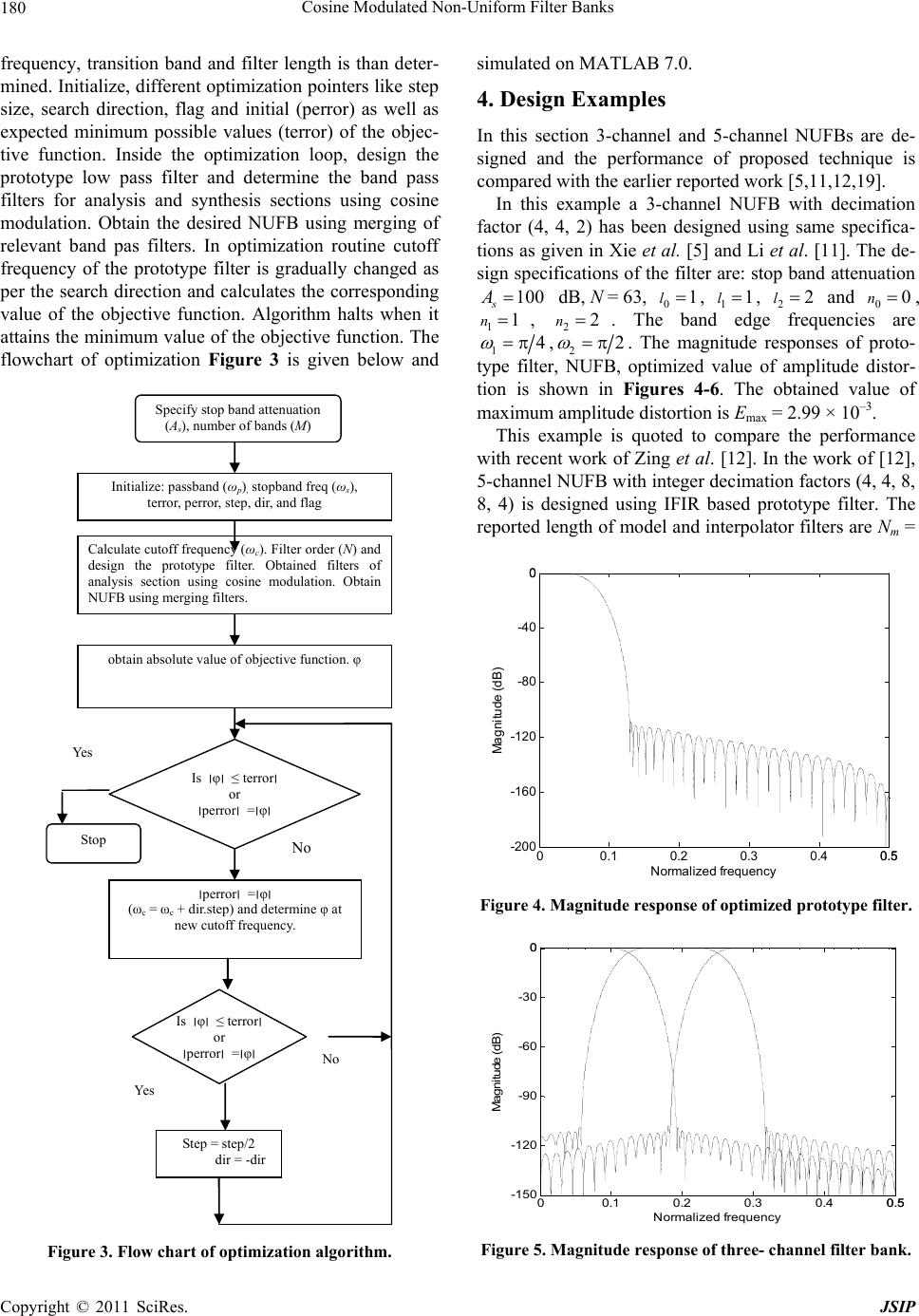 Cosine Modulated Non-Uniform Filter Banks 180 freque itioeter- ncy, transn band and filter length is than d mined. Initialize, different optimization pointers like step size, search direction, flag and initial (perror) as well as expected minimum possible values (terror) of the objec- tive function. Inside the optimization loop, design the prototype low pass filter and determine the band pass filters for analysis and synthesis sections using cosine modulation. Obtain the desired NUFB using merging of relevant band pas filters. In optimization routine cutoff frequency of the prototype filter is gradually changed as per the search direction and calculates the corresponding value of the objective function. Algorithm halts when it attains the minimum value of the objective function. The flowchart of optimization Figure 3 is given below and Specify stop band attenuation (A s ), number of bands (M) Initialize: passband (ω p ) , stopband freq (ω s ), terror, perror, step, dir, and flag Calculate cutoff frequency (ω c ). Filter order (N) and design the prototype filter. Obtained filters of analysis section using cosine modulation. Obtain NUFB using merging filters. obtain absolute value of objective function. φ ׀perror׀ =׀φ׀ (ω c = ω c + dir.step) and determine φ at new cutoff frequency. Step = step/2 dir = -dir Yes No Yes No Is ׀φ׀ ≤ terror׀ or ׀perror׀ =׀φ׀ Is ׀φ׀ ≤ terror׀ or ׀perror׀ =׀φ׀ Stop Figure 3. Flow chart of optimization algorithm. simul d 5-channel NUFBs are de- n fa ated on MATLAB 7.0. 4. Design Examples In this section 3-channel an signed and the performance of proposed technique is compared with the earlier reported work [5,11,12,19]. In this example a 3-channel NUFB with decimatio ctor (4, 4, 2) has been designed using same specifica- tions as given in Xie et al. [5] and Li et al. [11]. The de- sign specifications of the filter are: stop band attenuation 100 s A dB, N = 63, 01l , 11l, 22l and 00n , 11n , 22n . Thndeuencie e ba edg freqs are 14 ,22 NUFB, . The magnitude responses of proto- optimized value of amplitude distor- tion is shown in Figures 4-6. The obtained value of maximum amplitude distortion is Emax = 2.99 × 10⁻³. This example is quoted to compare the performa type filter, nce with recent work of Zing et al. [12]. In the work of [12], 5-channel NUFB with integer decimation factors (4, 4, 8, 8, 4) is designed using IFIR based prototype filter. The reported length of model and interpolator filters are Nm = 00.1 0.2 0.3 0.4 0.50.5 -200 -160 -120 -80 -40 00 Norm alized fr e quency Magnit ude (dB) Figure 4. Magnitude response of optimized prototype filter. 00.1 0.2 0.3 0.4 0.50.5 -15 0 -12 0 -90 -60 -30 00 Normalized f r eq uency M agnitude (dB) Figure 5. Magnitude response of three- channel filter bank. Copyright © 2011 SciRes. JSIP  Cosine Modulated Non-Uniform Filter Banks181 00.1 0.2 0.3 0.4 0.50.5 -5 -3.5 -2 -0.5 1 2.5 4 55 x 10-3 Norm a lized fr eq uen cy Amp litude distort ion Figure 6. Amplitude distortion plot. 1 and N= 39, respectively. Therefore, the obtained 3i overall filter length of IFIR prototype filter becomes N = (L.Nm+ Ni) = 163 [14]. Here, L is the stretch factor. In this example, 5-band NUFB is designed with the follow- ing specifications as in [12]: The band edge frequencies are 1π4 , 2π2 , 35π8 ,43π4 . In this case 0n1 = 2, 234=5 and l0 = 2, 1 l2, 2 l1, l3 = 1, l4 = 2. The obtained prototype filts tngth 163, the stop band attenuation As = 110 dB. The magnitude responses of prototype filter, filter bank and distortion parameters are shown in Fig- ures 7-9. The obtained resulting distortion parameter is maximum amplitude distortion Emax = 0.0065 dB. , n = 0. n = 4, n = 5, n 6, n = 8; ples for the NUFB are presented to er hahe le 5. Discussion Two design exam demonstrate effectiveness of the design. A three and five channel symmetric non-uniform filter banks were de- signed and the amplitude characteristics of analysis filters are shown in Figure 5 and Figure 8. The positive fre- 00.1 0.20.3 0.4 0.50.5 -150 -120 -90 -60 -30 00 Normalized fr e quen cy Magnitude (dB) 00.1 0.2 0.3 0.40.50.5 -150 -120 -90 -60 -30 00 Norma lized fr equency M agnitu de ( dB) Figure 8. Magnitude response of five-channel filter bank. 00.1 0.2 0.3 0.4 0.50.5 -8 -5.5 -3 -0.5 2 4.5 7 88x 10 -3 Normalized frequency Reconstruction er ror (dB) Figure 9. Amplitude distortion plot. quncy range is clearly divided into three and five non- e uniform bands. These filter banks have integer decima- tion factors. The filter lengths of analysis FIR filters are 63 and 85. For both the designs the Kaiser windowed LPF were used as initial filters for minimization of the performance function. And, as a tool for optimization, the linear iterative algorithm was utilized. Comparisons with Tree-Structure NUFBs show that the Tree-Structure can be either PR or NPR depending on the FBs used in the design. On the other hand proposed method can only design NPR FBs. The advantage of our method is that it can be used to design a feasible or non feasible partition NUFB with good performance. Since it is derived from uniform CMFBs by cosine modulating a prototype filter, its implementation also consists of one prototype filter and a discrete cosine transform (DCT). Since the number of parameter is reduced, the speed of convergence is faster, and filter bank with high attenuation can be de- signed. It is clear from Table 1 and Table 2 that for same decimation factors the proposed work provided better results for peak amplitude distortions (Emax). Figure 7. Magnitude response of optimized prototype filter. Copyright © 2011 SciRes. JSIP 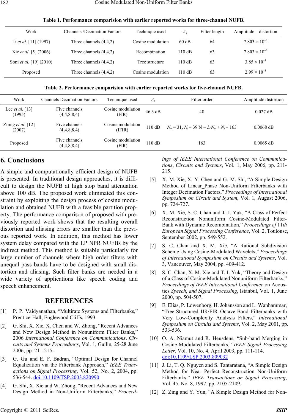 Cosine Modulated Non-Uniform Filter Banks Copyright © 2011 SciRes. JSIP 182 ision with earlier reported works for three-channel NUFB. Work Channels /Decimation Factors Technique used As Filter length Amplitude distortion Table 1. Performance compar Li et a1997) Cosine 60 dB l. [11] (Three channels (4,4,2) modulation 64 7.803 × 10⁻³ Xie et al. [5] (2006) Three channels (4,4,2) Recombination 110 dB63 7.803 × 10⁻³ S Cn oni et al. [19] (2010) Three channels (4,4,2) Tree structure 110 dB63 3.85 × 10⁻³ Proposed Three channels (4,4,2) osine modulatio110 dB63 2.99 × 10⁻³ Table 2. Performance comparision with earlier reported works for five-channel NUFB. Work Channels DecimsAmplitude distortionation Factors Technique used A Filter order Lee 3] C46.3 dB40 0.027 dB et al. [1 (1995) Five channels (4,4,8,8,4) osine modulation (FIR) Zijin Five channels Cosination 110 dBNm = 31, Ni = 39 N = L·Nm + Ni = 163 0.0068 dB Proposed Five channels Cosine m110 dB163 0.0065 dB g et al. [12] (2007) (4,4,8,8,4) e modul (IFIR) (4,4,8,8,4) odulation (FIR) . Conclusions ationally efficient design of NUFB REFERENCES [1] P. P. Vaidyans and Filterbanks,” Recent Advances dran, “Optimal Design for Channel 6 A simple and comput is presented. In traditional design approaches, it is diffi- cult to design the NUFB at high stop band attenuation above 100 dB. The proposed work eliminated this con- straint by exploiting the design process of cosine modu- lation and obtained NUFB with a feasible partition prop- erty. The performance comparison of proposed with pre- viously reported work shows that the resulting overall distortion and aliasing errors are smaller than the previ- ous reported work. In addition, this method has lower system delay compared with the LP NPR NUFBs by the indirect method. This method is suitable particularly for large number of channels where high order filters with unequal pass bands have to be designed with small dis- tortion and aliasing. Such filter banks are needed in a wide variety of applications like speech coding and speech enhancement. athan, “Multirate System Prentice-Hall, Englewood Cliffs, 1993. [2] G. Shi, X. Xie, X. Chen and W. Zhong, “ and New Design Method in Nonuniform Filter Banks,” 2006 International Conference on Communications, Cir- cuits and Systems Proceedings, Vol. 1, Guilin, 25-28 June 2006, pp. 211-215. [3] G. Gu and E. F. Ba Equalization via the Filterbank Approach,” IEEE Trans- actions on Signal Processing, Vol. 52, No. 2, 2004, pp. 536-544. doi:10.1109/TSP.2003.820990 [4] G. Shi, X. Xie and W. Zhong, “Recent Advances and New ings of IEEE International Conference on Communica- d of Linear_Phase Non-Uniform Filterbanks with Nonuniform Cosine-Modulated Filter- ed Wavelets,” Proceedings orm Filterbanks,” /FIR Octave-Band Filterbanks with dulated Filterbanks,” IEEE Signal Processing Design Method in Non-Uniform Filterbanks,” Proceed- tions, Circuits and Systems, Vol. 1, May 2006, pp. 211- 215. [5] X. M. Xie, X. Y. Chen and G. M. Shi, “A Simple Design Metho Integer Decimation Factors,” Proceedings of International Symposium on Circuit and System, Vol. 1, August 2006, pp. 724-727. [6] X. M. Xie, S. C. Chan and T. I. Yuk, “A Class of Perfect Reconstruction Bank with Dynamic Recombination,” Proceedings of 11th European Signal Processing Conference, Vol. 2, Toulouse, September 2002, pp. 549-552. [7] S. C. Chan and X. M. Xie, “A Rational Subdivision Scheme Using Cosine-Modulat of International Symposium on Circuits and Systems, Vol. 3, Vancouver, May 2004, pp. 409-412. [8] S. C. Chan, X. M. Xie and T. I. Yuk, “Theory and Design of a Class of Cosine-Modulated Nonunif Proceedings of IEEE International Conference on Acous- tics Speech, and Signal Processing, Istanbul, Vol. 1, June 2000, pp. 504-507. [9] E. Elias, P. Lowenborg, H. Johansson and L. Wanhammar, “Tree-Structured IIR Very Low-Complexity Analysis Filters,” International Symposium on Circuits and Systems, Vol. 2, May 2001, pp. 533-536. [10] O. A. Niamut and R. Heusdens, “Sub-band Merging in Cosine-Mo Letter, Vol. 10, No. 4, April 2003, pp. 111-114. doi:10.1109/LSP.2003.809032 [11] J. Li, T. Q. Nguyen and S. Tantaratana, “A Simple Method for Near Perfect Rec Design onstruction Non-Uniform Filterbanks,” IEEE Transactions on Signal Processing, Vol. 45, No. 8, 1997, pp. 2105-2109. [12] Z. Zing and Y. Yun, “A Simple Design Method for Non-  Cosine Modulated Non-Uniform Filter Banks183 International ns on C ew Delhi, 2001. rbanks,” Proceedings of IEEE In- ers for M-Band Uniform Cosine Modulated Filterbank,” Symposium on Microwave, Antenna, Propagation and EMC Technologies, 2007, pp. 1052-1055, [13] J. Lee and B. G. Lee, “A Design of Nonuniform Cosine Modulated Filterbanks,” IEEE Transactioircuits and System-II, Vol. 42, No. 1, November 1995, pp. 732- 737. [14] S. K. Mitra, “Digital Signal Processing,” Tata Mc-Graw Hill, N [15] J. D. Johnston, “A Filter Family Designed for Use in Quadrature Mirror Filte ternational Conference on Acoustics, Speech and Signal Processing, Denver, 1980, pp. 291-294. [16] C. D. Cresure and S. K. Mitra, “A Simple Method for Designing High-Quality Prototype Filt Pseudo QMF Banks,” Transactions on Signal Processing, Vol. 43, No. 4, 1995, pp. 1005-1007. doi:10.1109/78.376856 [17] Y. P. Lin and P. P. Vaidyanathan, “ Approach for the Desi A Kaiser Window gn of Prototype Filters of Co- sine-Modulated Filterbanks,” IEEE Signal Processing Letter, Vol. 5, No. 6, 1998, pp. 132-134. doi:10.1109/97.681427 [18] A. Jain, R. Saxena and S. C. Saxena, “An Simplified Design of C Improved and osine Modulated Pseudo QMF Filterbanks,” Digital Signal Processing, Vol. 16, No. 3, 2006, pp. 225-232. doi:10.1016/j.dsp.2005.11.001 [19] R. K. Soni and A. Jain, “An Optimized Design of Non- Uniform Filterbank Using Blackman Window Family,” International Journal of Signal and Image Processing, Vol. 1, No. 1, 2010, pp. 18-23. Copyright © 2011 SciRes. JSIP
|