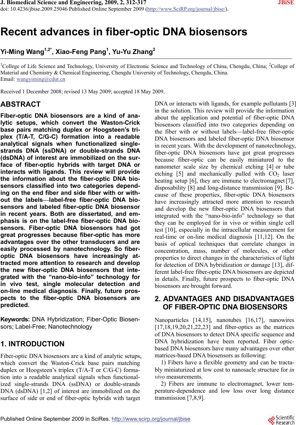
 J. Biomedical Science and Engineering, 2009, 2, 312-317 doi: 10.4236/jbise.2009.25046 Published Online September 2009 (http://www.SciRP.org/journal/jbise/ JBiSE ). Published Online September 2009 in SciRes. http://www.scirp.org/journal/jbise Recent advances in fiber-optic DNA biosensors Yi-Ming Wang1,2*, Xiao-Feng Pang1, Yu-Yu Zhang2 1College of Life Science and Technology, University of Electronic Science and Technology of China, Chengdu, China; 2College of Material and Chemistry & Chemical Engineering, Chengdu University of Technology, Chengdu, China. Email: wangyiming@cdut.cn Received 1 December 2008; revised 13 May 2009; accepted 18 May 2009. ABSTRACT Fiber-optic DNA biosensors are a kind of ana- lytic setups, which convert the Waston-Crick base pairs matching duplex or Hoogsteen’s tri- plex (T/A-T, C/G-C) formation into a readable analytical signals when functionalized single- strands DNA (ssDNA) or double-strands DNA (dsDNA) of interest are immobilized on the sur- face of fiber-optic hybrids with target DNA or interacts with ligands. This review will provide the information about the fiber-optic DNA bio- sensors classified into two categories depend- ing on the end fiber and side fiber with or with- out the labels—label-free fiber-optic DNA bio- sensors and labeled fiber-optic DNA biosensor in recent years. Both are dissertated, and em- phasis is on the label-free fiber-optic DNA bio- sensors. Fiber-optic DNA biosensors had got great progresses because fiber-optic has more advantages over the other transducers and are easily processed by nanotechnology. So fiber- optic DNA biosensors have increasingly at- tracted more attention to research and develop the new fiber-optic DNA biosensors that inte- grated with the “nano-bio-info” technology for in vivo test, single molecular detection and on-line medical diagnosis. Finally, future pros- pects to the fiber-optic DNA biosensors are predicted. Keywords: DNA Hybridization; Fiber-Optic Biosen- sors; Label-Free; Nanotechnology 1. INTRODUCTION Fiber-optic DNA biosensors are a kind of analytic setups, which convert the Waston-Crick base pairs matching duplex or Hoogsteen’s triplex (T/A-T or C/G-C) forma- tion into a readable analytical signals when functional- ized single-strands DNA (ssDNA) or double-strands DNA (dsDNA) [1,2] of interest are immobilized on the surface of side or end of fiber-optic hybrids with target DNA or interacts with ligands, for example pollutants [3] in the solution. This review will provide the information about the application and potential of fiber-optic DNA biosensors classified into two categories depending on the fiber with or without labels—label-free fiber-optic DNA biosensors and labeled fiber-optic DNA biosensor in recent years. With the development of nanotechnology, fiber-optic DNA biosensors have got great progresses because fiber-optic can be easily miniatured to the nanometer scale size by chemical etching [4] or tube etching [5] and mechanically pulled with CO2 laser heating setup [6], they are immune to electromagnet [7], disposability [8] and long-distance transmission [9]. Be- cause of these properties, fiber-optic DNA biosensors have increasingly attracted more attention to research and develop the new fiber-optic DNA biosensors that integrated with the “nano-bio-info” technology so that they can be employed for in vivo or within single cell test [10], especially in the intracellular measurement for real-time or on-line medical diagnosis [11,12]. On the basis of optical techniques that correlate changes in concentration, mass, number of molecules, or other properties to direct changes in the characteristics of light for detection of DNA hybridization or damage [13], dif- ferent label-free fiber-optic DNA biosensors are depicted in details. Finally, future prospects to fiber-optic DNA biosensors are brought forward. 2. ADVANTAGES AND DISADVANTAGES OF FIBER-OPTIC DNA BIOSENSORS Nanoparticles [14,15], nanotubes [16,17], nanowires [17,18,19,20,21,22,23] and fiber-optics as the matrices of DNA biosensors to detect DNA specific sequence and DNA hybridization have been reported. Fiber optic- based DNA biosensors have many advantages over other matrices-based DNA biosensors as following: 1) Fibers have a flexible geometry and can be tracta- bly miniaturized at low cost to nanosacle structure for in vivo measurements. 2) Fibers are immune to electromagnet, lower tem- perature-dependence and low loss over long distance transmission [7,8,9]. 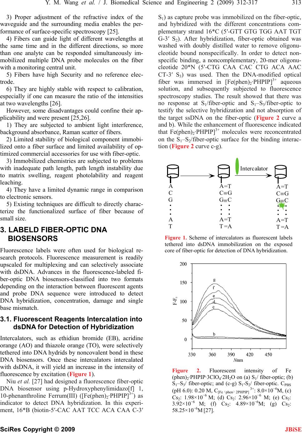 Y. M. Wang et al. / J. Biomedical Science and Engineering 2 (2009) 312-317 313 SciRes Copyright © 2009 JBiSE 3) Proper adjustment of the refractive index of the waveguide and the surrounding media enables the per- formance of surface-specific spectroscopy [25]. 4) Fibers can guide light of different wavelengths at the same time and in the different directions, so more than one analyte can be responded simultaneously im- mobilized multiple DNA probe molecules on the fiber with a monitoring central unit. 5) Fibers have high Security and no reference elec- trode. 6) They are highly stable with respect to calibration, especially if one can measure the ratio of the intensities at two wavelengths [26]. However, some disadvantages could confine their ap- plicability and were present [25,26]. 1) They are subjected to ambient light interference, background absorbance, Raman scatter of fibers. 2) Limited stability of biological component immobi- lized onto a fiber surface and limited availability of op- timized commercial accessories for use with fiber-optic. 3) Immobilized chemistries are subjected to problems with inadequate path length, path length instability due to matrix swelling, reagent photolability and reagent leaching. 4) They have a limited dynamic range in comparison to electronic sensors. 5) Existing techniques are difficult to directly charac- terize the functionalized surface of fiber because of small size. 3. LABELD FIBER-OPTIC DNA BIOSENSORS Fluorescence labels were often used for biological re- search protocols. Fluorescence measurement is readily upscaled for multiplexing and can selectively associate with dsDNA. Advances in the fluorescence-labeled fi- ber-optic DNA biosensors-classified into two formats depending on the interaction between fluorescent agents and probe DNA sequence were introduced to detect DNA hybridization, concentration, damage and single base mismatch. 3.1. Fluorescent Reagents Intercalation into dsDNA for Detection of Hybridization Intercalators, such as ethidiun bromide (EB), acridine orange (AO) and thiazole orange (TO), were selectively tethered into DNA hydrids by noncovalent bond in these DNA biosensors. Once these intercalators intercalated with dsDNA, it will yield an increase in the intensity of fluorescence by excitation (Figure 1). Niu et al. [27] had designed a fluorescence fiber-optic DNA biosensor using p-Hydroxyphenylimidazo[f] 1, 10-phenanthroline Ferrum(III) ([Fe(phen)2·PHPIP]3+) as indicator to detect DNA hybridization. In this experi- ment, 16*B (biotin-5′-CAC AAT TCC ACA CAA C-3′ S1) as capture probe was immobilized on the fiber-optic, and hybridized with the different concentrations com- plementary strand 16*C (5′-GTT GTG TGG AAT TGT G-3′ S 2). After hybridization, fiber-optic obtained was washed with doubly distilled water to remove oligonu- cleotide bound nonspecifically. In order to detect non- specific binding, a noncomplementary, 20-mer oligonu- cleotide 20*N (5′-CTG CAA CAC CTG ACA AAC CT-3′ S 3) was used. Then the DNA-modified optical fiber was immersed in [Fe(phen)2·PHPIP]3+ aqueous solution, and subsequently subjected to fluorescence spectroscopy studies. The result showed that there was no response at S1/fiber-optic and S1–S3/fiber-optic to testify the selective hybridization and not absorption of the target ssDNA on the fiber-optic (Figure 2 curve a and b). While the enhancement of fluorescence indicated that Fe(phen)2·PHPIP]3+ molecules were reconcentrated on the S1–S2/fiber-optic surface for the binding interac- tion (Figure 2 curve c-g). =T G C =T =A = = =T G C =T =A A C G A T = = = = A C G A T Intercalator A C G A T = = Figure 1. Scheme of intercalators as fluorescent labels tethered into dsDNA immobilization on the exposed core of fiber-optic for detection of DNA hybridization. Figure 2. Fluorescent intensity of Fe (phen)2·PHPIP·3ClO4·2H2O on (a) S1/ fiber-optic; (b) S1–S3/ fiber-optic; and (c-g) S1-S2/ fiber-optic. CPBS (pH 6.0): 0.20 M, C[Fe(phen)2PHPIP] 3+: 8.0×10⁻⁶M, (c) Cs2: 1.98×10⁻⁶ M; (d) Cs2: 2.96×10⁻⁶ M; (e) Cs2: 3.92×10⁻⁶ M; (f) Cs2: 4.89×10⁻⁶M; (g) Cs2: 58.25×10⁻⁶M [27]. 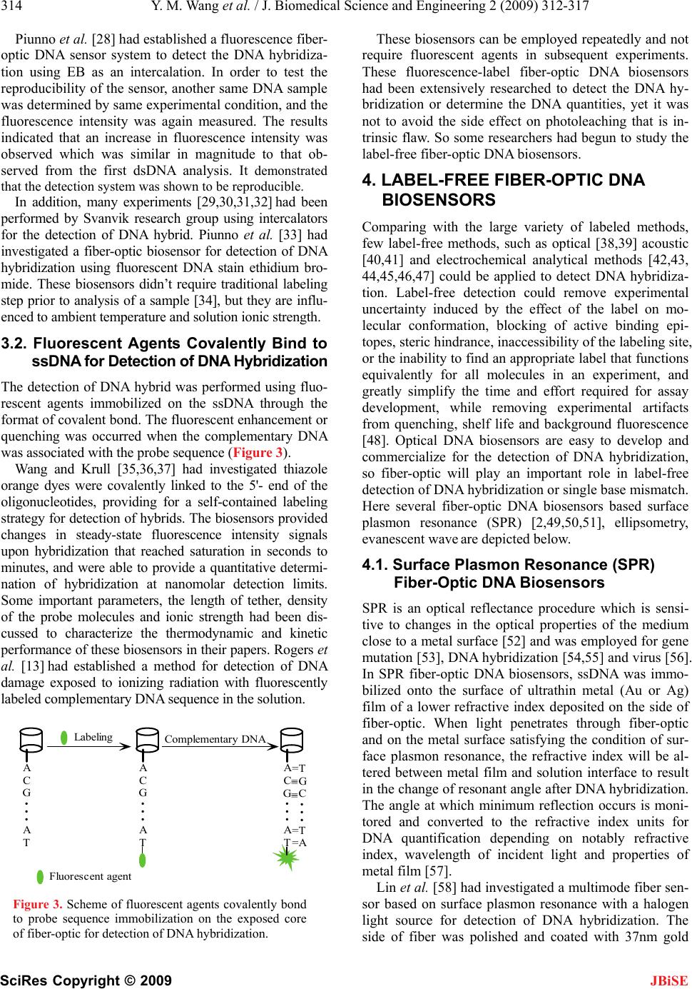 314 Y. M. Wang et al. / J. Biomedical Science and Engineering 2 (2009) 312-317 SciRes Copyright © 2009 JBiSE Piunno et al. [28] had established a fluorescence fiber- optic DNA sensor system to detect the DNA hybridiza- tion using EB as an intercalation. In order to test the reproducibility of the sensor, another same DNA sample was determined by same experimental condition, and the fluorescence intensity was again measured. The results indicated that an increase in fluorescence intensity was observed which was similar in magnitude to that ob- served from the first dsDNA analysis. It demonstrated that the detection system was shown to be reproducible. In addition, many experiments [29,30,31,32] had been performed by Svanvik research group using intercalators for the detection of DNA hybrid. Piunno et al. [33] had investigated a fiber-optic biosensor for detection of DNA hybridization using fluorescent DNA stain ethidium bro- mide. These biosensors didn’t require traditional labeling step prior to analysis of a sample [34], but they are influ- enced to ambient temperature and solution ionic strength. 3.2. Fluorescent Agents Covalently Bind to ssDNA for Detection of DNA Hybridization The detection of DNA hybrid was performed using fluo- rescent agents immobilized on the ssDNA through the format of covalent bond. The fluorescent enhancement or quenching was occurred when the complementary DNA was associated with the probe sequence (Figure 3). Wang and Krull [35,36,37] had investigated thiazole orange dyes were covalently linked to the 5'- end of the oligonucleotides, providing for a self-contained labeling strategy for detection of hybrids. The biosensors provided changes in steady-state fluorescence intensity signals upon hybridization that reached saturation in seconds to minutes, and were able to provide a quantitative determi- nation of hybridization at nanomolar detection limits. Some important parameters, the length of tether, density of the probe molecules and ionic strength had been dis- cussed to characterize the thermodynamic and kinetic performance of these biosensors in their papers. Rogers et al. [13] had established a method for detection of DNA damage exposed to ionizing radiation with fluorescently labeled complementary DNA sequence in the solution. A C G A T Labeling A C G A T Complementary DNA =T G C =T =A = = = = Fluorescent agent A C G A T Figure 3. Scheme of fluorescent agents covalently bond to probe sequence immobilization on the exposed core of fiber-optic for detection of DNA hybridization. These biosensors can be employed repeatedly and not require fluorescent agents in subsequent experiments. These fluorescence-label fiber-optic DNA biosensors had been extensively researched to detect the DNA hy- bridization or determine the DNA quantities, yet it was not to avoid the side effect on photoleaching that is in- trinsic flaw. So some researchers had begun to study the label-free fiber-optic DNA biosensors. 4. LABEL-FREE FIBER-OPTIC DNA BIOSENSORS Comparing with the large variety of labeled methods, few label-free methods, such as optical [38,39] acoustic [40,41] and electrochemical analytical methods [42,43, 44,45,46,47] could be applied to detect DNA hybridiza- tion. Label-free detection could remove experimental uncertainty induced by the effect of the label on mo- lecular conformation, blocking of active binding epi- topes, steric hindrance, inaccessibility of the labeling site, or the inability to find an appropriate label that functions equivalently for all molecules in an experiment, and greatly simplify the time and effort required for assay development, while removing experimental artifacts from quenching, shelf life and background fluorescence [48]. Optical DNA biosensors are easy to develop and commercialize for the detection of DNA hybridization, so fiber-optic will play an important role in label-free detection of DNA hybridization or single base mismatch. Here several fiber-optic DNA biosensors based surface plasmon resonance (SPR) [2,49,50,51], ellipsometry, evanescent wave are depicted below. 4.1. Surface Plasmon Resonance (SPR) Fiber-Optic DNA Biosensors SPR is an optical reflectance procedure which is sensi- tive to changes in the optical properties of the medium close to a metal surface [52] and was employed for gene mutation [53], DNA hybridization [54,55] and virus [56]. In SPR fiber-optic DNA biosensors, ssDNA was immo- bilized onto the surface of ultrathin metal (Au or Ag) film of a lower refractive index deposited on the side of fiber-optic. When light penetrates through fiber-optic and on the metal surface satisfying the condition of sur- face plasmon resonance, the refractive index will be al- tered between metal film and solution interface to result in the change of resonant angle after DNA hybridization. The angle at which minimum reflection occurs is moni- tored and converted to the refractive index units for DNA quantification depending on notably refractive index, wavelength of incident light and properties of metal film [57]. Lin et al. [58] had investigated a multimode fiber sen- sor based on surface plasmon resonance with a halogen light source for detection of DNA hybridization. The side of fiber was polished and coated with 37nm gold 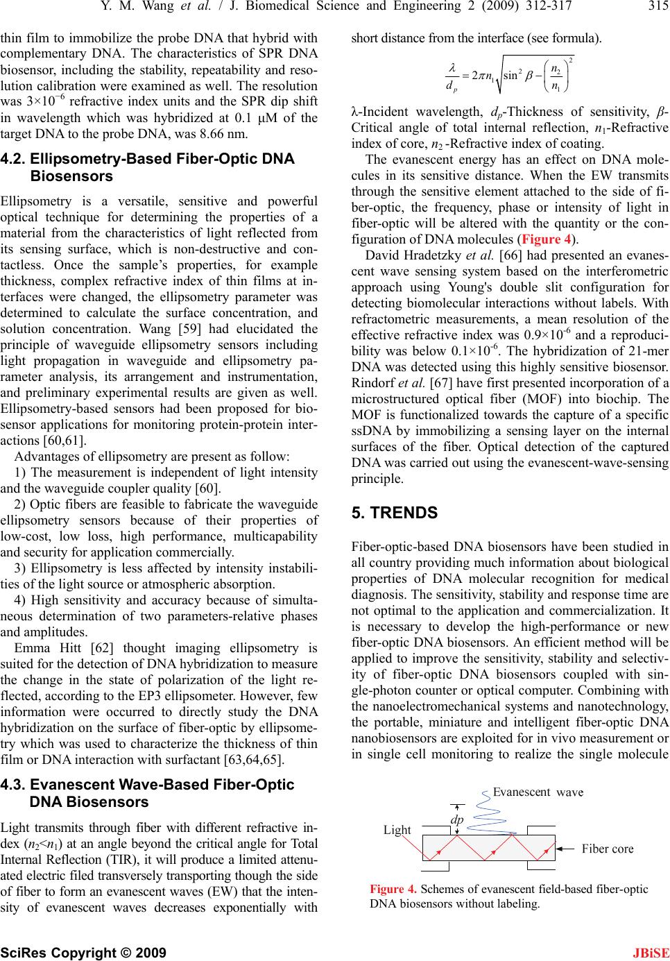 Y. M. Wang et al. / J. Biomedical Science and Engineering 2 (2009) 312-317 315 SciRes Copyright © 2009 JBiSE Advantages of ellipsometry are present as follow: thin film to immobilize the probe DNA that hybrid with complementary DNA. The characteristics of SPR DNA biosensor, including the stability, repeatability and reso- lution calibration were examined as well. The resolution was 3×10⁻⁶ refractive index units and the SPR dip shift in wavelength which was hybridized at 0.1 μM of the target DNA to the probe DNA, was 8.66 nm. 4.2. Ellipsometry-Based Fiber-Optic DNA Biosensors Ellipsometry is a versatile, sensitive and powerful optical technique for determining the properties of a material from the characteristics of light reflected from its sensing surface, which is non-d estructive and con- tactless. Once the sample’s properties, for example thickness, complex refractive index of thin films at in- terfaces were changed, the ellipsometry parameter was determined to calculate the surface concentration, and solution concentration. Wang [59] had elucidated the principle of waveguide ellipsometry sensors including light propagation in waveguide and ellipsometry pa- rameter analysis, its arrangement and instrumentation, and preliminary experimental results are given as well. Ellipsometry-based sensors had been proposed for bio- sensor applications for monitoring protein-protein inter- actions [60,61]. 1) The measurement is independent of light intensity and the waveguide coupler quality [60]. 2) Optic fibers are feasible to fabricate the waveguide ellipsometry sensors because of their properties of low-cost, low loss, high performance, multicapability and security for application commercially. 3) Ellipsometry is less affected by intensity instabili- ties of the light source or atmospheric absorption. 4) High sensitivity and accuracy because of simulta- neous determination of two parameters-relative phases and amplitudes. Emma Hitt [62] thought imaging ellipsometry is suited for the detection of DNA hybridization to measure the change in the state of polarization of the light re- flected, according to the EP3 ellipsometer. However, few information were occurred to directly study the DNA hybridization on the surface of fiber-optic by ellipsome- try which was used to characterize the thickness of thin film or DNA interaction with surfactant [63,64,65]. 4.3. Evanescent Wave-Based Fiber-Optic DNA Biosensors Light transmits through fiber with different refractive in- dex (n2<n1) at an angle beyond the critical angle for Total Internal Reflection (TIR), it will produce a limited attenu- ated electric filed transversely transporting though the side of fiber to form an evanescent waves (EW) that the inten- sity of evanescent waves decreases exponentially with short distance from the interface (see formula). 2 22 1 1 2sin p n n dn λ-Incident wavelength, dp-Thickness of sensitivity, β- Critical angle of total internal reflection, n1-Refractive index of core, n2 -Refractive index of coating. The evanescent energy has an effect on DNA mole- cules in its sensitive distance. When the EW transmits through the sensitive element attached to the side of fi- ber-optic, the frequency, phase or intensity of light in fiber-optic will be altered with the quantity or the con- figuration of DNA molecules (Figure 4). David Hradetzky et al. [66] had presented an evanes- cent wave sensing system based on the interferometric approach using Young's double slit configuration for detecting biomolecular interactions without labels. With refractometric measurements, a mean resolution of the effective refractive index was 0.9×10⁻⁶ and a reproduci- bility was below 0.1×10⁻⁶. The hybridization of 21-mer DNA was detected using this highly sensitive biosensor. Rindorf et al. [67] have first presented incorporation of a microstructured optical fiber (MOF) into biochip. The MOF is functionalized towards the capture of a specific ssDNA by immobilizing a sensing layer on the internal surfaces of the fiber. Optical detection of the captured DNA was carried out using the evanescent-wave-sensing principle. 5. TRENDS Fiber-optic-based DNA biosensors have been studied in all country providing much information about biological properties of DNA molecular recognition for medical diagnosis. The sensitivity, stability and response time are not optimal to the application and commercialization. It is necessary to develop the high-performance or new fiber-optic DNA biosensors. An efficient method will be applied to improve the sensitivity, stability and selectiv- ity of fiber-optic DNA biosensors coupled with sin- gle-photon counter or optical computer. Combining with the nanoelectromechanical systems and nanotechnology, the portable, miniature and intelligent fiber-optic DNA nanobiosensors are exploited for in vivo measurement or in single cell monitoring to realize the single molecule Figure 4. Schemes of evanescent field-based fiber-optic DNA biosensors without labeling.  316 Y. M. Wang et al. / J. Biomedical Science and Engineering 2 (2009) 312-317 SciRes Copyright © 2009 JBiSE detection. The kinetic studies demonstrated this surface modification to be superior to other methods of immobi- lization [68], so surface modification will be improved with advanced surface chemistry technique and new assembly technique to increase the stability, homogene- ity, lifetime and frequency of fiber-optic DNA biosen- sors. REFERENCES [1] Uddin, A. H., Piunno, P. A., Hudson, R. H., Damha M. J., and Krull U. J., (1997) Nucleic Acids Research, 25(20), 4139–4146. [2] Bates, P. J., Reddoch, J. F., Hansakul, P., Arrow, A., Dale, R., and Miller, D. M., (2002) Anal. Biochem., 307(2) 235–243. [3] Wang, J., Rivas, G., Cai, X., Palecek, E., Nielsen, P., Shiraishi, H., et al. (1997) Anal. Chim. Acta., 347(1), 1–8. [4] Hoffmann, P., Dutoit, B., and Salathé, R. P., (1995) Ul- tramicroscopy, 6, 165–170. [5] Stöckle, R., Fokas, C., Deckert, V., Zenobi, R., Sick, B., Hecht, B., et al. (1999) Appl. Phys. Lett., 75(2), 160–162. [6] Liu, X. M., Wang, J., and Li, D. C., (1998) Rev. Scient. Instrum., 69(9), 3439–3440. [7] Lee, B., (2003) Optical Fiber Technology, 9(2), 57–59. [8] Mitsuaki, W. and Kotaro, K., (2003) Sensors and Actua- tors B: Chemical, 89(1), 126–130. [9] Han, Y. G., Tran, T. V. A., Kim, S. H., and Lee, S. B., (2005) Opt. Lett., 30(11), 1282–1284. [10] Cullum, B. M., Griffin, G. D., Miller, G. H., and Vo-Dinh, T., (2000) Analytical Biochemistry, 277(1), 25–32. [11] Chen, X., Zhang, L., Zhou, K., Davies, E., Sugden, K., and Bennion, I., et al., (2007) Opt. Lett., 32(17), 2541–2543. [12] Vo-Dinh, T., Cullum, B. M., and Stokes, D. L., (2001) Sensors and Actuators B: Chemical, 74(1), 2–11. [13] Rogers, K. R., Apostol, A., Steen, Madsen, J., and Spencer, C. W., (2001) Analytica Chimica Acta, 444(1), 51–60. [14] Maxwell, D. J., Taylor, J. R., and Nie, S. M., (2002) J. Am. Chem. Soc., 124(32), 9606–9612. [15] Zhang, D., Chen, Y., Chen, H. Y., and Xia, X. H., (2004) Anal. Bioanal. Chem., 379(7), 1025–1030. [16] Li, J., Ng, H. T., Cassell, A., Fan, W., Chen, H., and Ye, Q., et al., (2003) Nano Lett., 3(5), 597–602. [17] Balasubramanian, K. and Burghard, M., (2006) Anal. Bioanal. Chem., 385(3), 452–468. [18] Li, Z., Rajendran, B., Kamins, T. I., Li, X., Chen, Y., and Williams, R. S., (2005) Applied Physics A: Materials Sci- ence & Processing, 80(6), 1257–1263. [19] Zheng, G. F., Patolsky, F., Cui, Y., Wang, W. U., and Lie- ber, C. M., (2005) Nature Biotechnology, 23(10), 1294–1301. [20] Cui, Y., Wei, Q. Q, Park, H. K, and Lieber, C. M., (2001) Science, 293 (5533), 1289–1292. [21] Li, Z., Chen, Y., Li, X., Kamins, T. I., Nauka, K., and Williams, R. S., (2004) Nano Lett., 4(2), 245–247. [22] Park, I., Li, Z. Y., Li, X. M., Pisano, A. P., and Williams, R. S., (2007) Biosensors and Bioelectronics, 22(9), 2065–2070. [23] Kamins, T. I., Sharma, S., Yasseri, A. A., Li, Z., and Straznicky, J., (2006) Nanotechnology, 17(11), S291– S297. [24] Lou, J. Y., Tong, L. M., and Ye, Z. Z., (2005) Optics ex- press, 13(6), 2135–2140. [25] Marazuela, M. and Moreno-bondi, M., (2002) Anal. Bio- anal. Chem., 372(5), 664–682. [26] Mehrvar, M., Bis, C., Scharer, J. M., Moo, M., and Lu- ong, J. H., (2000) Analytical Sciences, 16(7), 677–692. [27] Niu S. Y., Wang S. J., Shi C., Zhang S. S., (2008) J Fluo- resc, 18, 227-235. [28] Piunno, P. A. E., Krull, U. J., Hudson, H. E., Damha, M. J., and Cohen, H., (1994) Analytica Chimica Acta, 288(3), 205–214. [29] Svanvik, N., Stahlberg, A., Sehlstedt, U., Sjoback, R., and Kubsita, M., (2000) Anal. Biochem., 287(1), 179–182. [30] Isacsson, J., Cao, H., Ohlsson, L., Nordgren, S., Svanvik, N., and Westman, G., et al., (2000) Mol. Cell Probes, 14(5), 321–328. [31] Svanvik, N., Westman, G., Wang, D., and Kubsita, M., (2000) Anal. Biochem., 281(1), 26–35. [32] Svanvik, N., Nygren, J., Westman, G., Kubsita, M., (2001) J. Am. Chem. Soc., 123(5), 803–809. [33] Piunno, P. A. E., Krull, U. J., Hudson, H. E., Damha, M. J., and Cohen, H., (1995) Anal. Chem., 67(15), 2635–2643. [34] Monk, D. J. and Walt, D. R., (2004) Anal. Bioanal. Chem., 379(7), 931–945. [35] Wang, X. F. and Krull, U. J., (2002) Analytica Chimica Acta, 470(1), 57–70. [36] Wang, X. F. and Krull, U. J., (2005) J. Mater. Chem., 15(27), 2801-2809. [37] Wang, X. F. and Krull, U. J., (2005) Bioorg. Med. Chem. Lett., 15(6), 1725–1729. [38] Baird, C. L. and Myszka, D. G., (2001) J. Mol. Recognit., 14(5), 261–268. [39] Rich, R. L. and Myszka, D. G., (2002) J. Mol. Recognit., 15(6), 352–376. [40] Hur, Y., Han, J., Seon, J., Pak, Y. E., and Roh, Y., (2005) Sensors and Actuators A: Physical, 120(2), 462-467. [41] Minunni, M., Mannelli, I., Spiriti, M. M., Tombelli, S., and Mascini, M., (2004) Analytica Chimica Acta, 526(1), 19-25. [42] Xu, Y., Jiang, Y., Yang, L., He, P. G., and Fang, Y. Z., (2005) Chinese Journal of Chemistry, 23(12), 1665–1670. [43] Chen, Y., Elling, Lee, Y., and Chong, S., (2006) J. Phys. Conf. Ser., 34, 204–209. [44] Kerman, K., Morita, Y., Takamura, Y., and Tamiya, E., (2005) Anal. Bioanal. Chem., 381(6), 1114–1121. [45] Kerman, K., Morita, Y., Takamura, Y., and Tamiya, E., (2003) Electrochem. Comm., 5(10), 887–889. [46] Peng, H., Soeller, C., Vigar, N., Kilmartin, P. A., Cannell, M. B., Bowmaker, G. A., et al. (2005) Biosensors and Bioelectronics, 20(9), 1821–1828.  Y. M. Wang et al. / J. Biomedical Science and Engineering 2 (2009) 312-317 317 SciRes Copyright © 2009 JBiSE [47] Mir1, M. and Katakis, I., (2005) Anal. Bioanal. Chem., 381(5), 2618–2642. [48] Li, P. Y., Lin, B., Gerstenmaier, J., and Cunningham, B. T., (2004) Sensors and Actuators. B: Chemical, 99(1), 6–13. [49] Bianchi, N., Rutigliano, C., Tomassetti, M., Feriotto, G., Zorzato, F., and Gambari, R., (1997) Clin. Diagn. Virol., 8(3), 199–208. [50] Minunni, M., Tombelli, S., Mariottie, E., and Mascini, M., (2001) Fresenius J. Anal. Chem., 369(7), 589–593. [51] Persson, B., Stenhag, K., Nilsson, P., Larsson, A., Uhlen, M., and Nygren, P., (1997) Anal. Biochem., 246(1), 34–44. [52] Collings, A. F. and Caruso, F., (1997) Rep. Prog. Phys., 60(11), 1397–1445. [53] Jiang, T., Minunni, M., Wilson, P., Zhang, J., Turner, A. P. F., and Mascini, M., (2002) Biosensors and Bioelectron- ics, 20(10), 1939–1945. [54] Peterlinz, K. A., Georgiadis, R. M., Herne, T. M., and Tarlov, M., (1997) J. Am. Chem. Soc., 119(14), 3401–3402. [55] Peterson, A. W., Wolf, L. K., and Georgiadis, R. M., (2002) J. Am. Chem. Soc., 124(49), 14601–14607. [56] Bianchi, N., Rutigliano, C., Tomassetti, M., Feriotto, G., Zorzato, F., and Gambari, R., (1997) Clin. Diagn. Virol., 8(3), 199–208. [57] Kambhampati, D. K. and Knoll, W., (1999) Current Opinion in Colloid & Interface Science, 4(4), 273–280. [58] Lin, H. Y., Tsai, W. H., Tsao, Y. C., and Sheu, B. C., (2007) Applied Optics, 46(5), 800–806. [59] Wang, J. Y., (1992) SPIE Fiber Optic Medical and Fluo- rescent Sensors and Applications, 1648, 44–50. [60] Tiberg, F., Brink, C., Hellsten, M., and Holmberg, K., (1992) Colloid & Polymer Science, 270(12), 1188–1193. [61] Mahltig, B., Werner, C., Müller, M., Jérôme, R., and Stamm, M., (2001) Journal of Biomaterials Science, Polymer Edition, 12(9), 995–1010. [62] Emma Hitt, (2005) Drug Discovery & Development, http://cmliris.harvard.edu/news/2004/DrugDiscDev_Sep 04.pdf. [63] McLoughlin, D. and Langevin, D., (2004) Physico- chemical and Engineering Aspects, 250, 79–87. [64] Wong, A. K. Y. and Krull, U. J., (2005) Anal. and Bioanal. Chem., 383(2), 187–200. [65] Shabani, A., Mak, A. W. H., Gerges, I., Cuccia, L. A., and Lawrence, M. F., (2006) Talanta, 70(3), 615–623. [66] Hradetzky, D., Mueller, C., and Reinecke, H., (2006) J. Opt. A: Pure Appl. Opt., 8(7), S360–S364. [67] Rindorf. L., Høiby, P. E., Jensen, J. B., Pedersen, L. H., Bang, O., and Geschke, O., (2006) Anal. Bioanal. Chem. 385(8), 1370–1375. [68] Zeng, J., Almadidy, A., Watterson, J., and Krull, U. J., (2003) Sensors and Actuators B: Chemical, 90(1), 68–75.
|