Paper Menu >>
Journal Menu >>
 Materials Sciences and Applicatio n, 2011, 2, 971-976 doi:10.4236/msa.2011.28130 Published Online August 2011 (http://www.SciRP.org/journal/msa) Copyright © 2011 SciRes. MSA 971 Nanostructures on Surface of SrTiO3 Single Crystals Treated by Plasma Nicolay Kulagin1,2*, Jablan Dojcilovic3, Ellen Hieckmann4 1Joint Venture “Firma SIFA”, Kharkov, Ukraine; 2Nikopol Institute Zaporozhye National University, Zaporozhye, Ukraine; 3 Physics Department, University of Belgrade, Belgrade, Serbia; 4Institut für Angewandte Physik/Halbleiterphysik, Technische Universität Dres- den, Dresden, Germany. Email: *nkulagin@bestnet.kharkov.ua Received April 6th, 2010; revised May 20th, 2010; accepted May 31st, 2011. ABSTRACT Modification of a surface of strontium titanate single crystals as pure as doped with Mn (Ni) or Nd (Sm) ions after plasma treatment was studied by combination of scanning electron microscopy and atomic force microscopy techniques. Valence shift method for characteristic X-ray lines was used for study of stoichiometry violation and oxidation state of ions on the crystals surface after plasma treatment. One- and two-level ordered systems of unit crystallites sized of about 10–7 - 10–10 m were discovered on samples surface after plasma treatment with energy density of about 5 - 20 (40) J·cm–2. Oxidation state of Ti ions and stoichiometry of the surface changed essentially on background of high stability of strontium ions valence. Keywords: Ordered Nano-Scale Structure, Strontium Titanate, Plasma, Change In Structure And Ion’S Valence 1. Introduction Strontium titanate crystals, SrTiO3, have been studied for a long time [1-4], and interest to the crystal has recently grown up after discovery of high-temperature supercon- ductors and unique properties of the samples [5-7]. Selected experimental data concerning to relation of a stoichiometric composition and properties of SrTiO3 (shortly, STO) single crystals were presented in [8-14]. Depending on the crystal composition, the cubic crystal- line lattice parameter a (space group Pm¯3m) changes from a = 3.9051 Å in bulk stoichiometric samples to a = 3.9102 Å in oxygen-deficient STO accompanied by a variation of the dielectric constant r from 360 to 200 and less [7-14]. Variation in stoichiometric composition of the Sr+2Ti+4O–23 crystals can results in a transition of a part of Ti+4 ions to Ti+3 oxidation state [15-17] causing a sig- nificant influence to dielectrical, optical and other prop- erties of the samples. More than 20% of Ti+4 ions change valence to Ti+3 state (electronic configuration 3d1) that was observed in non-stoichiometric SrxTiyOz and TixOy single crystals [17,18]. Recently, the area of investigation of bulk samples and crystal surfaces under plasma-flow and ionizing irradia- tion has been expanded. Experimental data presented for materials after plasma treatment show the wide opportu nity for modification of the surface of metals and semi- conductors [19-21]. As a wide-band gap semiconductor, strontium titanate could be a good object for that kind of application, too. Preliminary results for STO surface pub- lished in [22,23] confirm this assumption. The paper presents analysis of the exposure of mid- dle-energy hydrogen and helium plasma to the pure and doped with Me and RE ions STO single crystals, we also report on the effect of crystal growth conditions to modi- fication of the sample surface, morphology and possible change of the crystals properties under plasma treatment. 2. Samples and Experimental Procedures Perfect pure (reference), standard (nominally un-doped) and STO single crystals doped with selected iron (Me) or rare earths (RE) ions, grown by the Verneuil technique using different growth conditions, were chosen for the study. Reference samples were grown by used of a fine and high-purity mixture. For the samples permittivity 0 equals (360 ± 5). Permittivity 0 for nominally un-doped samples varied from 290 to 340. Optical absorption spectra of the most samples consist of additional bands peaked at 430,  Nanostructures on Surface of SrTiO Single Crystals Treated by Plasma 972 3 520 and 620 nm. The refractive index changes from n = 2.4 to 2.2. STO samples doped with Me ions (Mn and Ni) or RE ones (Nd and Sm) were grown using technology de- scribed in [6, 10, 16]. Magnitude of 0 for the Me doped samples varies from 200 to 280. The studied permittivity r for STO doped with RE ions was less and mentioned above: r = ((80 – 160) ± 5). The main properties of the examined samples are plotted in Table 1. Atomic force microscopy (AFM-NP 206), scanning electron microscopy (SEM-JEOL 840A, energy-dispersive X ray line spectroscopy (EDX) techniques were used to study the surface of the samples before and after plasma treatment. Additionally a scanning electron microscope with field emission gun (thermal Schottky field emitter), type Zeiss ULTRA55 was used for the investigation of the crystal surface after plasma treatment. All images were obtained by an In-lense detector for secondary elec- trons, applying an electron acceleration voltage of 15 kV. 3. Results and Discussion 3.1. Plasma Treatment Two magneto-plasma compressors, MPC, were used for plasma-treatment of the sample surfaces. A detailed de- scription of experimental setups and methods can be found in [19-21]. Briefly, the MPC is a single-stage quasi-stationary plasma accelerator. The self-magnetic- field-sample shielding of the anode rods diminishes the level of the erosion. Anode rods are connected by a car- rier, which enables MPC flux magnitude in order of magnitude of 1020 cm–2·s–1 and energy values of 5, 10, 15 and 20 J·cm–2 per impulse, respectively [19,20]. Time of quasi-stable state plasma impulse varied at (5 - 50) × 10–6 s. The local temperature T on the surface of the samples was of about 2500 K. According to data of ellipsometri- cal measurements, thickness of the near-surface layer involved by plasma-treatment was of about 10–6 m. and less. SEM and AFM images of the crystal surface in ini- tial state were similar to the pure and doped samples. Exemplary, SEM images of the surface for pure and selected doped STO samples (with Ni or Nd doping ions) treated by both magneto-plasma accelerators mentioned above plasma-flow with an energy density (dose) up 5 to 20 J·cm–2 are given in Figures 1-4. The images given in Figures 1-2 were received after treatment at the “long time” quasi-stationary impulse (τ ~ 150 mks). The image shown in Figures 3-4 were observed with help of “short time impulse” device (τ ~ 5 mks). AFM images for pure and doped SrTiO3: Ni (Mn) and SrTiO3: Nd samples including additional information about the surface morphology after plasma treatment by dose of about 10 - 20 J·cm–2 are given on Figures 5-8. The images for other tested samples are similar. Figure 1. SEM image of pure SrTiO3 surface after plasma treatment by dose of about 5 J·cm–2. Figure 2. SEM image of SrTiO3: Nd surface after plasma treatment by dose of about 10J·cm-2. Figure 3. SEM image of SrTiO3: Nd surface after plasma treatment by dose of about 15 J·cm–2. Systems of crystallites shown on Figures 1-8 for se- lected samples area are very complex. For the pure sam- ples and energy of about 10 J·cm–2, the system of unit crystallites with size of about 10–6 m (Figure 5) on area. with size of about several mkm were discovered. For Copyright © 2011 SciRes. MSA  Nanostructures on Surface of SrTiO Single Crystals Treated by Plasma973 3 Figure 4. SEM image of SrTiO3: Nd surface after plasma treatment by dose of about 20 J·cm–2 Figure 5. AFM image of pure SiTiO3 surface after plasma treatment of about 10 J·cm–2. Figure 6. AFM image of SiTiO3: Ni after plasma treatment of about 15 J·cm-2. Figure 7. AFM image of SrTiO3: Mn surface after plasma treatment at dose 10 J.cm-2. Figure 8. AFM image of SrTiO3: Nd surface after plasma treatment at dose 20 J.cm–2. other samples and doze of plasma treatment we observe quasi-ordered systems of nano-scale size crystallites (Figures 3-4 and 6-7).The systems of crystallites with size by about 10–9 m grown on surface of more “large” crystallites with size by about 10–6 m (see Figure 8, too) was observed, too. Height of the unit plasma generated peaks on surface is less than 100 nm (see Figures 5 and 7) and less than 50 nm for two-levels nano-structures (Figures 3, 4, 6 and 8). Similar changes in STO surface morphology were discovered for other pure and doped STO samples (doped with Me and RE ions) after plasma-treatment using different doses (5 20 J·cm–2). 3.2. Oxidation State of the Ions It is well known oxidation state of ions and stoihiometry composition are strongly relates to selected properties of compounds. It can be assumed, that plasma treatment changes the stoichiometric relation in samples and oxida- tion state of ions. For verification in the oxidation state of Ti and Sr ions and the possible changing ratio of the atomic concentrations CSr/CTi, the method of valence shift of X ray lines, VSXRL, described in [10,16,22] was used. The dependence of the energy of the characteristic fluorescence X ray lines, XRL, EX +n on oxidation state of an ion is a basis of the method. The valence shift magni- tude, VS of XRL, EX, is determined as the difference in the energy of XRL for the ion Me+n and for the same ion Men±1 with other valence: 1nn XX X EE E (1) where EX +n (EX +n±1) is the energy of XRL of ion in “+n”(or “+n±1”) oxidation state, respectively [9,23]. The accurate ab initio theoretical expressions for the energy of TiKα1 and SrKα1 XRL for the ions in a cluster [9,18,23] were used for detailed analysis. Me+n → Me+n±1 oxidation state transition for Me or RE ions is accompanied by change (negative for Me+n → Me+n+1 transition and posi- tive for Me+n → Me+n – 1 one) of the energy of Kα1 or Lα1 XRL of about 1eV [9-10]. Copyright © 2011 SciRes. MSA 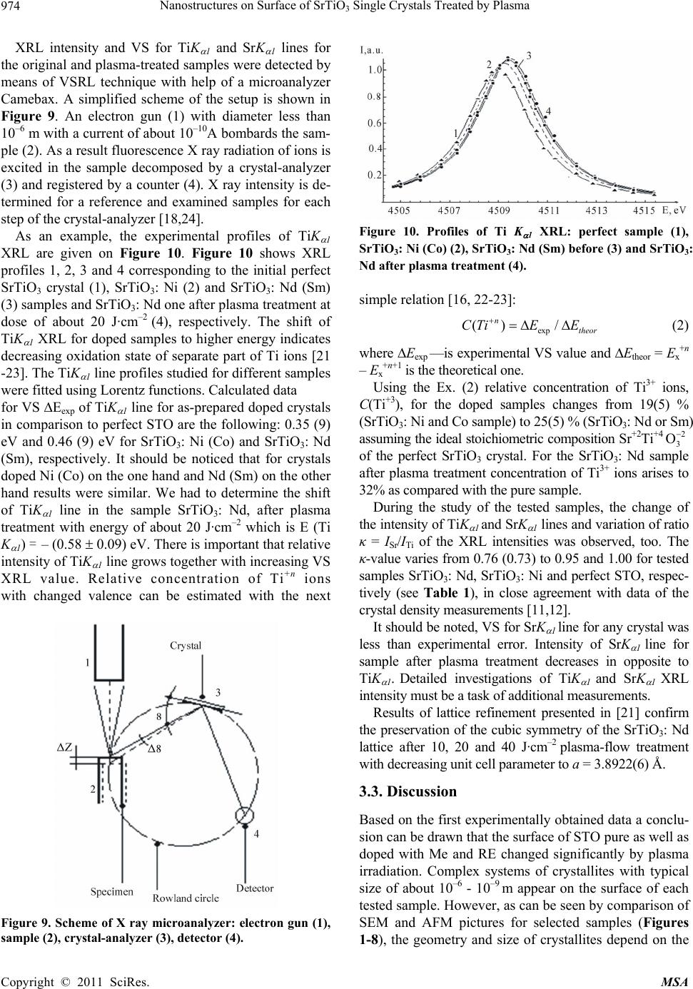 Nanostructures on Surface of SrTiO3 Single Crystals Treated by Plasma Copyright © 2011 SciRes. MSA 974 XRL intensity and VS for TiK 1 and SrK 1 lines for the original and plasma-treated samples were detected by means of VSRL technique with help of a microanalyzer Camebax. A simplified scheme of the setup is shown in Figure 9. An electron gun (1) with diameter less than 10–6 m with a current of about 10–10A bombards the sam- ple (2). As a result fluorescence X ray radiation of ions is excited in the sample decomposed by a crystal-analyzer (3) and registered by a counter (4). X ray intensity is de- termined for a reference and examined samples for each step of the crystal-analyzer [18,24]. Figure 10. Profiles of Ti K 1 XRL: perfect sample (1), SrTiO3: Ni (Co) (2), SrTiO3: Nd (Sm) before (3) and SrTiO3: Nd after plasma treatment (4). As an example, the experimental profiles of TiK 1 XRL are given on Figure 10. Figure 10 shows XRL profiles 1, 2, 3 and 4 corresponding to the initial perfect SrTiO3 crystal (1), SrTiO3: Ni (2) and SrTiO3: Nd (Sm) (3) samples and SrTiO3: Nd one after plasma treatment at dose of about 20 J·cm–2 (4), respectively. The shift of TiK 1 XRL for doped samples to higher energy indicates decreasing oxidation state of separate part of Ti ions [21 -23]. The TiK 1 line profiles studied for different samples were fitted using Lorentz functions. Calculated data simple relation [16, 22-23]: exp () / n theor СTiE E (2) where Eexp —is experimental VS value and Etheor = Ex+n – Ex+n+1 is the theoretical one. Using the Ex. (2) relative concentration of Ti3+ ions, C(Ti+3), for the doped samples changes from 19(5) % (SrTiO3: Ni and Co sample) to 25(5) % (SrTiO3: Nd or Sm) assuming the ideal stoichiometric composition Sr+2Ti+4 2 3 O of the perfect SrTiO3 crystal. For the SrTiO3: Nd sample after plasma treatment concentration of Ti3+ ions arises to 32% as compared with the pure sample. for VS Eexp of TiK 1 line for as-prepared doped crystals in comparison to perfect STO are the following: 0.35 (9) eV and 0.46 (9) eV for SrTiO3: Ni (Co) and SrTiO3: Nd (Sm), respectively. It should be noticed that for crystals doped Ni (Co) on the one hand and Nd (Sm) on the other hand results were similar. We had to determine the shift of TiK 1 line in the sample SrTiO3: Nd, after plasma treatment with energy of about 20 J·cm–2 which is E (Ti K 1) = – (0.58 0.09) eV. There is important that relative intensity of TiK 1 line grows together with increasing VS XRL value. Relative concentration of Ti+n ions During the study of the tested samples, the change of the intensity of TiK 1 and SrK 1 lines and variation of ratio κ = ISr/ITi of the XRL intensities was observed, too. The κ-value varies from 0.76 (0.73) to 0.95 and 1.00 for tested samples SrTiO3: Nd, SrTiO3: Ni and perfect STO, respec- tively (see Table 1), in close agreement with data of the crystal density measurements [11,12]. with changed valence can be estimated with the next It should be noted, VS for SrK 1 line for any crystal was less than experimental error. Intensity of SrK 1 line for sample after plasma treatment decreases in opposite to TiK 1. Detailed investigations of TiK 1 and SrK 1 XRL intensity must be a task of additional measurements. Results of lattice refinement presented in [21] confirm the preservation of the cubic symmetry of the SrTiO3: Nd lattice after 10, 20 and 40 J·cm–2 plasma-flow treatment with decreasing unit cell parameter to a = 3.8922(6) Å. 3.3. Discussion Based on the first experimentally obtained data a conclu- sion can be drawn that the surface of STO pure as well as doped with Me and RE changed significantly by plasma irradiation. Complex systems of crystallites with typical size of about 10–6 - 10–9 m appear on the surface of each tested sample. However, as can be seen by comparison of SEM and AFM pictures for selected samples (Figures 1-8), the geometry and size of crystallites depend on the Figure 9. Scheme of X ray microanalyzer: electron gun (1), sample (2), crystal-analyzer (3), detector (4). 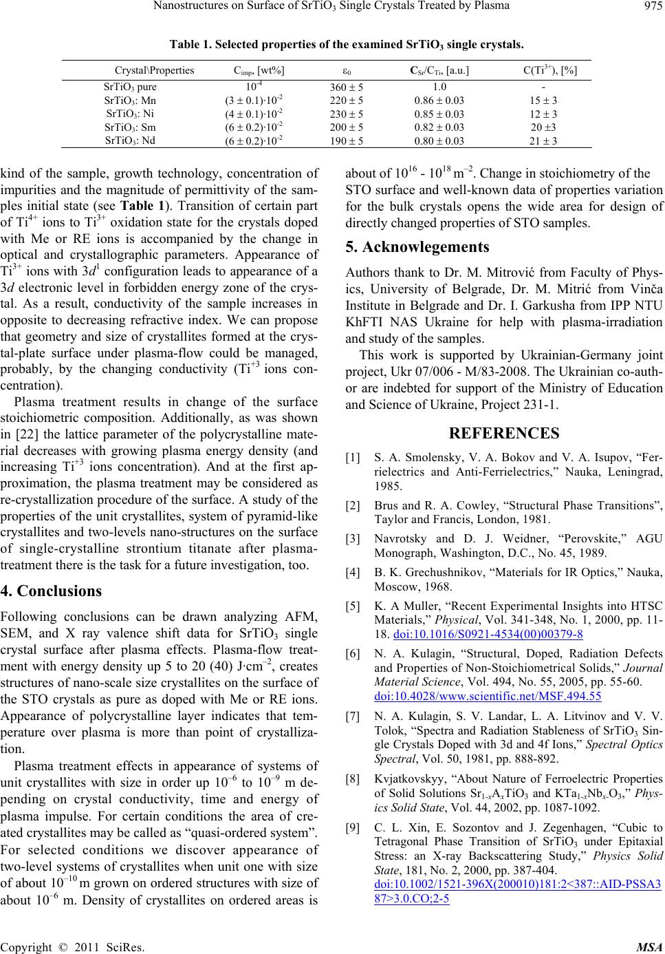 Nanostructures on Surface of SrTiO Single Crystals Treated by Plasma 975 3 Table 1. Selected properties of the examined SrTiO3 single crystals. Crystal\Properties Cimp, [wt%] 0 CSr/CTi, [a.u.] C(Ti3+), [%] SrTiO3 pure 10-4 360 5 1.0 - SrTiO3: Mn (3 0.1)·10-2 220 5 0.86 0.03 15 3 SrTiO3: Ni (4 0.1)·10-2 230 5 0.85 0.03 12 3 SrTiO3: Sm (6 0.2)·10-2 200 5 0.82 0.03 20 3 SrTiO3: Nd (6 0.2)·10-2 190 5 0.80 0.03 21 3 kind of the sample, growth technology, concentration of impurities and the magnitude of permittivity of the sam- ples initial state (see Table 1). Transition of certain part of Ti4+ ions to Ti3+ oxidation state for the crystals doped with Me or RE ions is accompanied by the change in optical and crystallographic parameters. Appearance of Ti3+ ions with 3d1 configuration leads to appearance of a 3d electronic level in forbidden energy zone of the crys- tal. As a result, conductivity of the sample increases in opposite to decreasing refractive index. We can propose that geometry and size of crystallites formed at the crys- tal-plate surface under plasma-flow could be managed, probably, by the changing conductivity (Ti+3 ions con- centration). Plasma treatment results in change of the surface stoichiometric composition. Additionally, as was shown in [22] the lattice parameter of the polycrystalline mate- rial decreases with growing plasma energy density (and increasing Ti+3 ions concentration). And at the first ap- proximation, the plasma treatment may be considered as re-crystallization procedure of the surface. A study of the properties of the unit crystallites, system of pyramid-like crystallites and two-levels nano-structures on the surface of single-crystalline strontium titanate after plasma- treatment there is the task for a future investigation, too. 4. Conclusions Following conclusions can be drawn analyzing AFM, SEM, and X ray valence shift data for SrTiO3 single crystal surface after plasma effects. Plasma-flow treat- ment with energy density up 5 to 20 (40) J·cm–2, creates structures of nano-scale size crystallites on the surface of the STO crystals as pure as doped with Me or RE ions. Appearance of polycrystalline layer indicates that tem- perature over plasma is more than point of crystalliza- tion. Plasma treatment effects in appearance of systems of unit crystallites with size in order up 10–6 to 10–9 m de- pending on crystal conductivity, time and energy of plasma impulse. For certain conditions the area of cre- ated crystallites may be called as “quasi-ordered system”. For selected conditions we discover appearance of two-level systems of crystallites when unit one with size of about 10–10 m grown on ordered structures with size of about 10–6 m. Density of crystallites on ordered areas is about of 1016 - 1018 m–2. Change in stoichiometry of the STO surface and well-known data of properties variation for the bulk crystals opens the wide area for design of directly changed properties of STO samples. 5. Acknowlegements Authors thank to Dr. M. Mitrović from Faculty of Phys- ics, University of Belgrade, Dr. M. Mitrić from Vinča Institute in Belgrade and Dr. I. Garkusha from IPP NTU KhFTI NAS Ukraine for help with plasma-irradiation and study of the samples. This work is supported by Ukrainian-Germany joint project, Ukr 07/006 - M/83-2008. The Ukrainian co-auth- or are indebted for support of the Ministry of Education and Science of Ukraine, Project 231-1. REFERENCES [1] S. A. Smolensky, V. A. Bokov and V. A. Isupov, “Fer- rielectrics and Anti-Ferrielectrics,” Nauka, Leningrad, 1985. [2] Brus and R. A. Cowley, “Structural Phase Transitions”, Taylor and Francis, London, 1981. [3] Navrotsky and D. J. Weidner, “Perovskite,” AGU Monograph, Washington, D.C., No. 45, 1989. [4] B. K. Grechushnikov, “Materials for IR Optics,” Nauka, Moscow, 1968. [5] K. A Muller, “Recent Experimental Insights into HTSC Materials,” Physical, Vol. 341-348, No. 1, 2000, pp. 11- 18. doi:10.1016/S0921-4534(00)00379-8 [6] N. A. Kulagin, “Structural, Doped, Radiation Defects and Properties of Non-Stoichiometrical Solids,” Journal Material Science, Vol. 494, No. 55, 2005, pp. 55-60. doi:10.4028/www.scientific.net/MSF.494.55 [7] N. A. Kulagin, S. V. Landar, L. A. Litvinov and V. V. Tolok, “Spectra and Radiation Stableness of SrTiO3 Sin- gle Crystals Doped with 3d and 4f Ions,” Spectral Optics Spectral, Vol. 50, 1981, pp. 888-892. [8] Kvjatkovskyy, “About Nature of Ferroelectric Properties of Solid Solutions Sr1-xAxTiO3 and KTa1-xNbx-O3,” Phys- ics Solid State, Vol. 44, 2002, pp. 1087-1092. [9] C. L. Xin, E. Sozontov and J. Zegenhagen, “Cubic to Tetragonal Phase Transition of SrTiO3 under Epitaxial Stress: an X-ray Backscattering Study,” Physics Solid State, 181, No. 2, 2000, pp. 387-404. doi:10.1002/1521-396X(200010)181:2<387::AID-PSSA3 87>3.0.CO;2-5 Copyright © 2011 SciRes. MSA 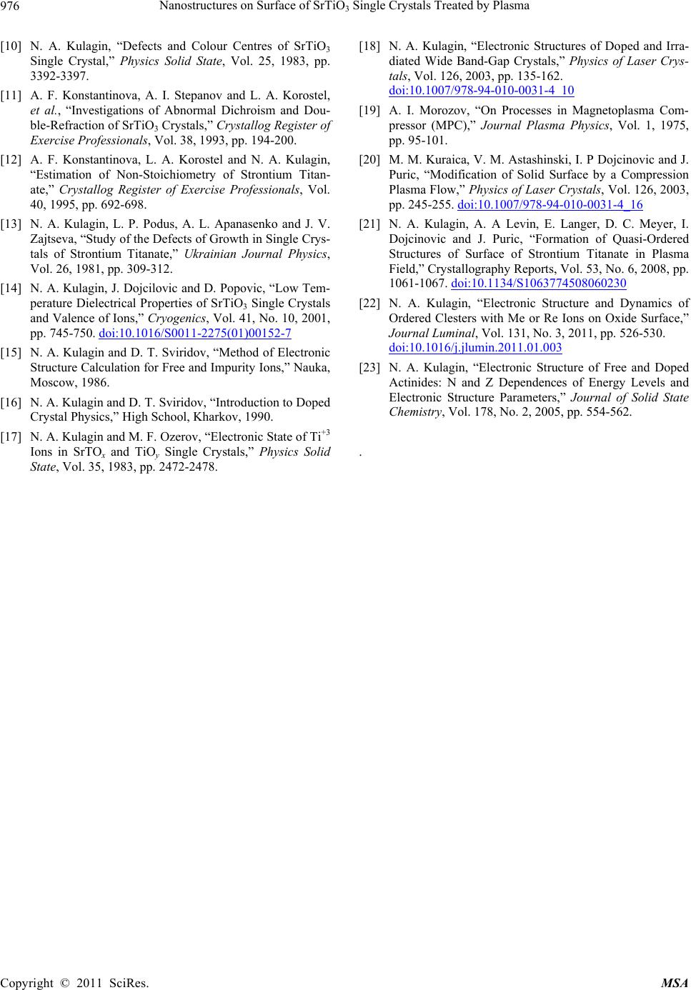 Nanostructures on Surface of SrTiO Single Crystals Treated by Plasma 976 3 [10] N. A. Kulagin, “Defects and Colour Centres of SrTiO3 Single Crystal,” Physics Solid State, Vol. 25, 1983, pp. 3392-3397. [11] A. F. Konstantinova, A. I. Stepanov and L. A. Korostel, et al., “Investigations of Abnormal Dichroism and Dou- ble-Refraction of SrTiO3 Crystals,” Crystallog Register of Exercise Professionals, Vol. 38, 1993, pp. 194-200. [12] A. F. Konstantinova, L. A. Korostel and N. A. Kulagin, “Estimation of Non-Stoichiometry of Strontium Titan- ate,” Crystallog Register of Exercise Professionals, Vol. 40, 1995, pp. 692-698. [13] N. A. Kulagin, L. P. Podus, A. L. Apanasenko and J. V. Zajtseva, “Study of the Defects of Growth in Single Crys- tals of Strontium Titanate,” Ukrainian Journal Physics, Vol. 26, 1981, pp. 309-312. [14] N. A. Kulagin, J. Dojcilovic and D. Popovic, “Low Tem- perature Dielectrical Properties of SrTiO3 Single Crystals and Valence of Ions,” Cryogenics, Vol. 41, No. 10, 2001, pp. 745-750. doi:10.1016/S0011-2275(01)00152-7 [15] N. A. Kulagin and D. T. Sviridov, “Method of Electronic Structure Calculation for Free and Impurity Ions,” Nauka, Moscow, 1986. [16] N. A. Kulagin and D. T. Sviridov, “Introduction to Doped Crystal Physics,” High School, Kharkov, 1990. [17] N. A. Kulagin and M. F. Ozerov, “Electronic State of Ti+3 Ions in SrTOx and TiOy Single Crystals,” Physics Solid State, Vol. 35, 1983, pp. 2472-2478. [18] N. A. Kulagin, “Electronic Structures of Doped and Irra- diated Wide Band-Gap Crystals,” Physics of Laser Crys- tals, Vol. 126, 2003, pp. 135-162. doi:10.1007/978-94-010-0031-4_10 [19] A. I. Morozov, “On Processes in Magnetoplasma Com- pressor (MPC),” Journal Plasma Physics, Vol. 1, 1975, pp. 95-101. [20] M. M. Kuraica, V. M. Astashinski, I. P Dojcinovic and J. Puric, “Modification of Solid Surface by a Compression Plasma Flow,” Physics of Laser Crystals, Vol. 126, 2003, pp. 245-255. doi:10.1007/978-94-010-0031-4_16 [21] N. A. Kulagin, A. A Levin, E. Langer, D. C. Meyer, I. Dojcinovic and J. Puric, “Formation of Quasi-Ordered Structures of Surface of Strontium Titanate in Plasma Field,” Crystallography Reports, Vol. 53, No. 6, 2008, pp. 1061-1067. doi:10.1134/S1063774508060230 [22] N. A. Kulagin, “Electronic Structure and Dynamics of Ordered Clesters with Me or Re Ions on Oxide Surface,” Journal Luminal, Vol. 131, No. 3, 2011, pp. 526-530. doi:10.1016/j.jlumin.2011.01.003 [23] N. A. Kulagin, “Electronic Structure of Free and Doped Actinides: N and Z Dependences of Energy Levels and Electronic Structure Parameters,” Journal of Solid State Chemistry, Vol. 178, No. 2, 2005, pp. 554-562. . Copyright © 2011 SciRes. MSA |