Circuits and Systems, 2016, 7, 726-734
Published Online May 2016 in SciRes. http://www.scirp.org/journal/cs
http://dx.doi.org/10.4236/cs.2016.76062
How to cite this paper: Shanmugam, S.K., Ramachandran, M., Kanagaraj, K.K. and Lo ganathan, A. (2016) Sensorless Control
of Four-Switch Inverter for Brushless DC Motor Drive and Its Simulation. Circuits and Systems, 7, 726-734.
http://dx.doi.org/10.4236/cs.2016.76062
Sensorless Control of Four-Switch
Inverter for Brushless DC Motor Drive
and Its Simulation
Sathish Kumar Shanmugam1*, Meenakumari Ramachandran2, Krishna Kumar Kanagaraj1,
Anbarasu Loganathan3
1Department of EEE, Jansons Institute of Technology, Coimbatore, India
2Department of EEE, Kongu Engineering College, Er ode, In dia
3Department of EEE, Erode Sengunthar Engineering College, Perundurai, India
Received 1 March 2016; accepted 9 May 2016; published 12 May 2016
Copyright © 2016 by authors and Scientific Research Publishing Inc.
This work is licensed under the Creative Commons Attribution International License (CC BY).
http://creativ ecommon s.org/l icenses/by /4.0/
Abstract
The major function of this proposed research is to control the speed of the brushless DC motor
with sensor less control for fou r-swi tch three phase inverter. This proposed system is simplified
the topological structure of the conventional s ix-s witc h three phase inverter. In this prop osed
method , a new structure of four-switch three phase inverter [1] with reduced number of sw itch es
for system is introduced to reduce the mechanical com mu tati on, switch ing losses that occur in the
six-switch method. The proposed inverter fed brushless DC motor used in sensorless control
schemes which is used for sensing positioning signals. To improve sensor less control perfor-
mance, four-switch electronic commutation modes based proportional intergral controller scheme
is implemented. In this four-switch three phase inverter reduction of switch es, low cost control
and saving of hall sensor were incorporated. The feasibility of the proposed sensor less control
four-s witch three phase inverter fed brushless DC motor drive is implemented, analysed using
MATLAB/SIMULINK, effective simulation results have been validated out successfully.
Keywords
Brushless DC Motor, Four-Switch Three Phase Inverter, Proportional Integral Controller,
Sensorless C on t rol
*
Corresponding author.
S. K. Shanmugam et al.
727
1. Introduction
In recent times, the brushless DC motor is becoming popular in different applications because of its high effi-
ciency, high power factor, lower maintenance, simple control and high torque. The proposed block diagram of
the research is shown in the Figure 1. Usually, brushless motors are excited by six-swi tch three phase inverter
as shown i n Figure 3. On t he o the r hand, co st -effective design is becoming one of the most imperative concerns
for the modern motor control research. Several researchers with simulation [1] [2] developed new power inver-
ters with condensed fatalities and expenses. Among these developments, the three-phase inve rt er s wit h o nl y fo ur
switches, as shown in Figure 2 is striking solution. In assessment with the normal three-phase voltage-source
inverter with six switches, the most important descriptions of this proposed converter play dual role: the first i s
the reduction of s witches and freewheeling diode count; the second is the reduction of conduction losses. The y
used position sen sors to achieve co mmutation contro l of brushless DC motors. However, position sensors make
the total system more expensive, larger in volume and a lesser amount of dependable. On the other hand, sensor
control for six-switch thr e e-phase brushless DC motors has had many successful applications. Almost all are
sensor control schemes for six-switch thre e-phase brushless D C motors have to d etect the zero-crossing point of
voltage waveforms from unexcited windings to estimate position of the rotor; however it is not possible to ac-
complish sensorless control schemes. So four -switch three phase brushless DC motor is incorporated and vari-
ous vo ltage s output are carried out.
2. Proposed Four-Switch Three Phase Inverter Brushless DC Motor Drive Systems
Usuall y, Br ushless DC motors ar e excited b y Six-switch three phase inverter as shown in Figure 1, have lot o f
Commutation Problems and Switch Leg fai lure a nd lar ge amo unt of Switching Lo sses. On t he othe r hand , cos t-
Figure 1 . Conventional six-switch three phase inverter brushless DC motor drive systems.
Figure 2 . Block diagram of proposed four-switch three phase inverter brushless DC motor drive systems.
S. K. Shanmugam et al.
728
effective design is becoming one of the most imperative concerns for the modern motor control research In order
to Overcome this, Several researchers developed new Power inverters with condensed fatalities and expenses.
The three-phase inverters with only four switches, as shown in Figure 3 is striking solution for Six-Switch
Inverter to reduce mechanical Strength and Switching Losses. In additional to that with t he normal three-phase
volta ge-source inverter with Four switches, the most important descriptions of this proposed converter plays
dual role i) the first is the reduction of Switches and Freewheeling diode count; ii) the second is the reduction of
conduction losses. They used Position sensors to achieve commutation (Mechanical) control of Brushless DC
motors.
The Proposed Four-switch thr ee phas e inver ter B rushle ss DC M otor Drive Syste ms follo ws the switchi ng se-
quenc e as shown i n the Table 1.
Amon g the imp lement s, the t hree pha se inver ters ha ve onl y four switche s, the main descrip tion of these pro-
posed inverter are reduction of switches and conduction losses. Until now, reduced components have been ap-
plied in AC inductio n motor dr ives, ho wever no w a da y the B rushl ess DC motor dr ives ar e usi ng due to it s hi gh
power factor, high speed, high torque, simple control and lo wer maintenance. The Four-Switch Three Phase In-
verter (Four-switch Three Phase Inverter) used in six commutation modes based on current control and Sensor
less control schemes. [2] developed Brushless DC motor drives with trapezoidal back electromotive force
(EM F) using t he Four-Switch Three -P hase Invert er. T he four-space-vector scheme was used in the six commu-
tatio n mo des base d o n cur re nt c ontr ol. In t hes e Br ushle ss D C dri ve co n figura tio n, t he D C suppl y give n to Four -
switch in ve r ter it converts DC power to three phase AC power.
In proposed method single phase to three phase converter back end consists of four switches (T1 to T6). In
three phase Brushless DC motor, two phases A and B are connected to the two legs of the Four-switch Three
phase inverter and the third phase C is connected to the centre point of the capacitor. Phase C is directly con-
nected to the Brushless DC motor, so the phase C current is not directly controlled [3].
Figure 3 . Proposed four-switch three phase inverter brushless DC motor drive systems.
Table 1 . Switching sequence of four-switch three phase inverter.
Modes Activ e Phases Si lent phases Switching devices
Mode I Phases B and C A
Mode II Phases A and B C And
Mode III Phases A and C B
Mode IV Phases B and C A And
Mode V Phases A and B C And
Mode VI Phases A and C B
S. K. Shanmugam et al.
729
0
abc
SSS++=
(1)
( )
c ab
S SS=−+
(2)
Therefore, phase C indirectly controlled by phase A and phase B. For Brushless DC motors with a trapezoidal
back EMF, is required to produce a constant electric torque. The proposed voltage Pulse Width Modula-
tion(PWM) scheme for Four-switc h three phase inverter requires six commutation modes which are (X, 0), (1,
0), (1, X), (X, 1), (0, 1) and (0, X) [4]. Here “X” stands for D on’t care conditions.
Back EMF Compensation
As three-phase Brushless DC motor is motivated with six-step 120˚ control process [5] [6]. Therefore the con-
ducti o n i nte rva l of one p hase i s 1 2 0 ˚. Therefore, the Back-EMF zero-crossing detecting performance is based on
only two phases of a Brushless DC Motor.The Basic switching sequence of Four-switch three phase inverter
available in SenSorless [7] [8] are shown in Table 1 are incorporated in this proposed work and their symbol
parenthesis of the switch ON/OFF states are and indicates as (phases A and B). “X” denotes the ON and OFF
state for both the high-side and low-side switching devices in the similar leg, “1” designates the ON condition
used for the high-side switching device and “0” designates the OFF condition used for the low-side switch ing
contriva nc e .
This conventional voltage PWM scheme provides a discharging loop between the capacitor and the low-side
switch additionally causes non-rectangular stator current waveforms which are harmful for constant torque, as
shown in Figure 4. Similar situations occur in Mode IV. There are three stages corresponding to (0, 0), (0, 1)
and ( 1, 0) c orresp ondingl y, in Mode II meant fo r the novel vo ltage P ulse width modula tion method . Simila r sit-
uations apply to Mode V. The new stage of this novel Pulse width modulation scheme in Modes II and V is in-
troduced to turn OFF all power devices to prevent the capacitor discharging from the low-side switch. Further-
more, the supply voltages in Modes II and V are double of those in the other four Modes while the Pulse width
moduation duty cycle in Modes I, III, IV of those in the Mode II and IV. The commutation sequence and the
Pulse widt h mod ulat ion d ut y are s hown in Ta ble 1 . Motor are connected to the power source at one time instant
so the third phase can be used to detect zero-crossing [9] of the Back-EMF voltage performed by In general
Figure 4 . Back EMF and phase current waveforms of brushless DC motor.
S. K. Shanmugam et al.
730
When phase A and phase B are connected to the source, phase C is floating. No current is going through this
phase. This conducting interval lasts 60 electrical degrees, which is called commutation step. This is described
by the following conditions:
If A p hase High, B phase Low : which is ana lysed as general equa t ions.
Norma lly,
££ £0abc++=
(3)
(4)
32 2
bev dc
VV= +
(5)
32 2
cew dc
VV= +
(6)
In these equations, forward voltage drop of Insulated bipolar transistor and freewheeling diode is ignored.
Ho weve r, in the four -switch c onver ter ba sed o n the four switching o pera tion, the gener atio n of 12 0˚ conducting
and a 60˚ non-conducting current profiles is essentially complicated. That resource the conventional Pulse width
modulation schemes employed for four-switch induction motor drives cannot be directly applied to Brushless
DC motor drives with sensorless [10]. This lead to the improvement of a novel control scheme called Direct
Current Controlle d Pulse width modulation sche me
3. Results and Discussions
The simulation of proposed research four-switch Brushless DC Motor is carried by Simulink and its Simulink
model are shown if Figure 5.
To generate the pulse width modulation signals subsystems are proposed which is shown in Figure 6. The
reference speed is set and rotor position sensor speed sensed are given to t he controller if it is equal it is send to
the controller or error is generated and rectified and it is given to the controller then the switches generates the
Pulses.
The Pulse width modulation signals generated by the switches from the output of controller are shown in
Figure 7. It is carried out by voltage and timeperiod and the results are taken from simulink environment.
The DC voltage which is fed an input suppl y gives the outp ut after then rectificatio n which is present inbuilt
gives pure D C voltage of 40V it also consists of voltage regulat or whose out put is sho wn in Figure 8.
The Brushless DC motor proposed in this research is three phase compare to [11] [12], fro m four -swi tch in-
Figure 5 . Simulation model of proposed four-switch three phase inverter system.
S. K. Shanmugam et al.
731
Figure 6 . Subsystem of Pulse width modulation generation for switches (T1-T4).
Figure 7 . PWM generation for switches (T1-T4).
Figure 8 . D C volta ge waveform of four-switch three phase inverter.
S. K. Shanmugam et al.
732
verter the inp ut voltage is fed better o ne is obtained . Each phase can varied at the input voltage of 40V which is
sho wn in the Figure 9. It is carr ied out by voltage and time pe riod the outp ut of P hase A, B, C are structured by
using Simulink model.
The main propose of this research is to conce ntrate on speed and backe mf compared to co nventional as in [13]
[14]. To determine the speed all other parameters values are taken in to important consideration DC voltage of
pure after from voltage regulation is inverted and is fed to Brushless motor three phase whose current are sensed
by rotor position sensor whose phase currents are shown in Figure 10 and the speed of the motor is excellent
enough achieved of 800 rpm with less number of switc hing losses compared to six-switch in verter, which is
sho wn in Figure 11.
In Figure 12, it is speed of 1450 rpm is measured using tachometer compared to the Six switches our pro-
posed work achieves less speed is achieved with low loss.
The trapezoidal Back Emf generated using four-switch inve rte r ar e sho wn in Figure 13 which is hi gh eno ug h
generated by the controller to drive motor.
Figure 9 . Phase voltage waveforms of four-switch three phase i nverter.
Figure 1 0. Phase current of the Sensorless four switch three phase inverter Brushless DC motor.
S. K. Shanmugam et al.
733
Figure 1 1. Spee d of the Sensorless four-switch three phase inverter Brushless DC motor.
Figure 12. Speed r es ponse and phase current of the sensorless six-switch three ph as e inverter brushless DC motor.
Figure 1 3. Back EMF of FSTPI brushless DC motor.
S. K. Shanmugam et al.
734
4. Conclusion
In this research, we significantly use sensorless control so for angle position hall sensing fully avoided. Brush-
less DC drives which is preferable for compact, low maintenance and high reliability system in order to reduce
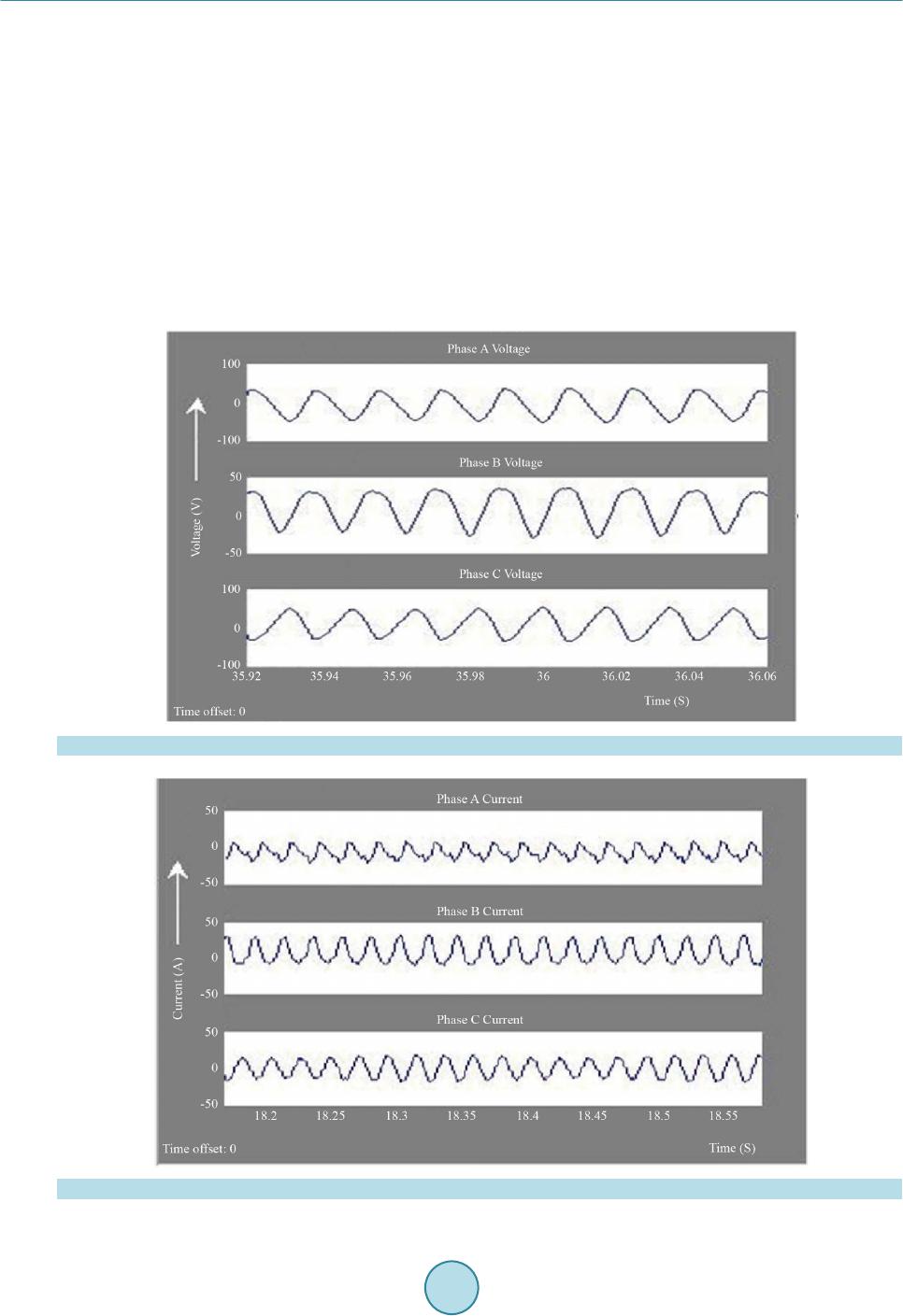
the mechanical strength so it proposed and convenient simulation results are carried out. The simulation of the
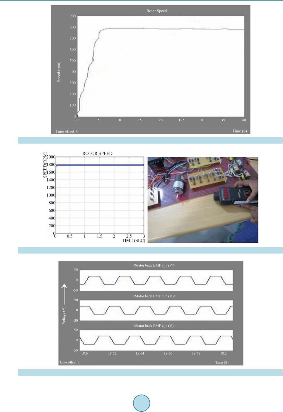
brushless DC motor is done using the software MATLAB/SIMULINK whose back EMF, phase voltage phase
current, rotor speed waveform are analyzed and incorporated the speed of rotor is 800 rpm are analyse d. In this
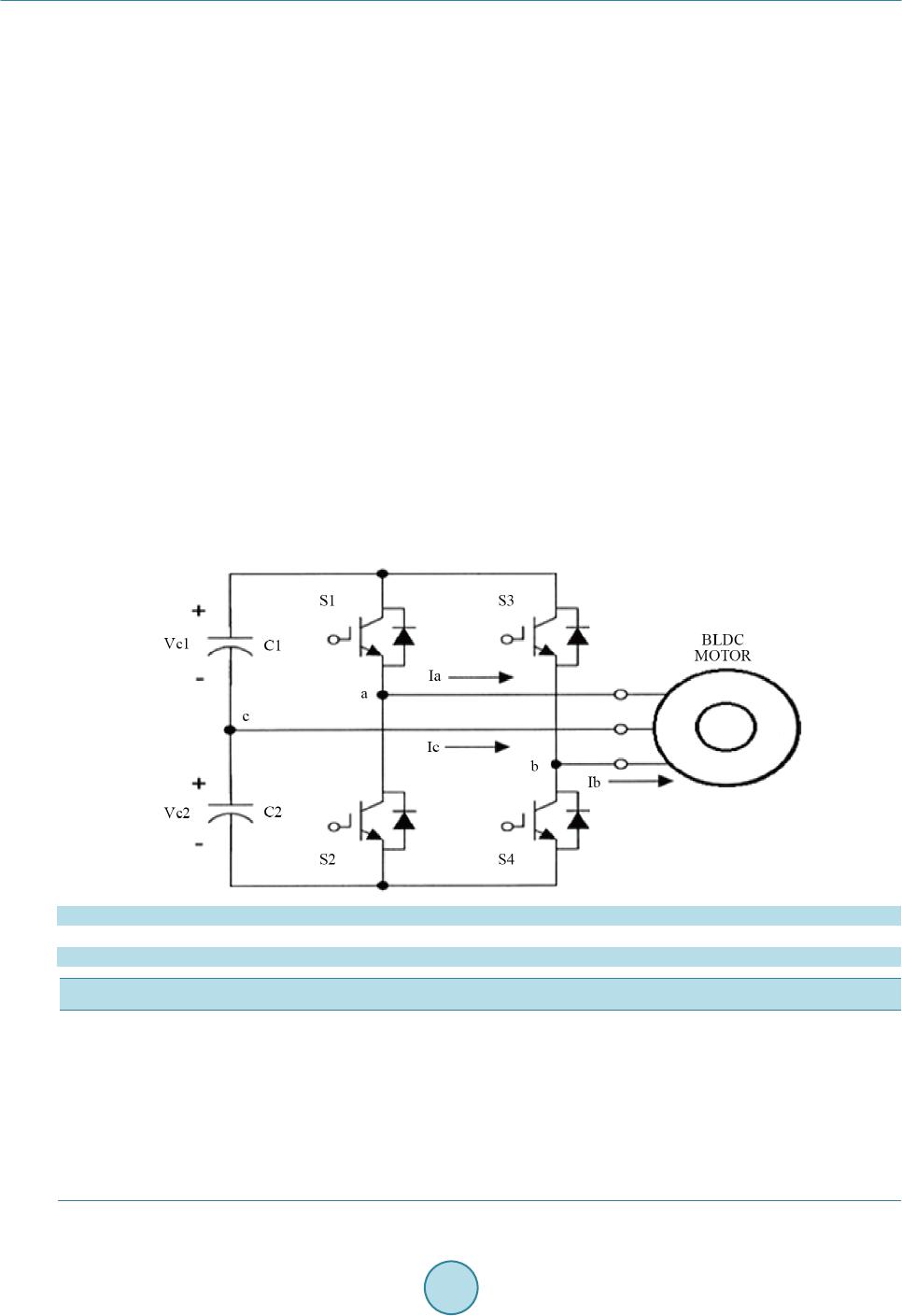
proposed converter used less number of ins ulated b ipola r switche s whic h e valuate the conve nti o na l co nve rt er . In
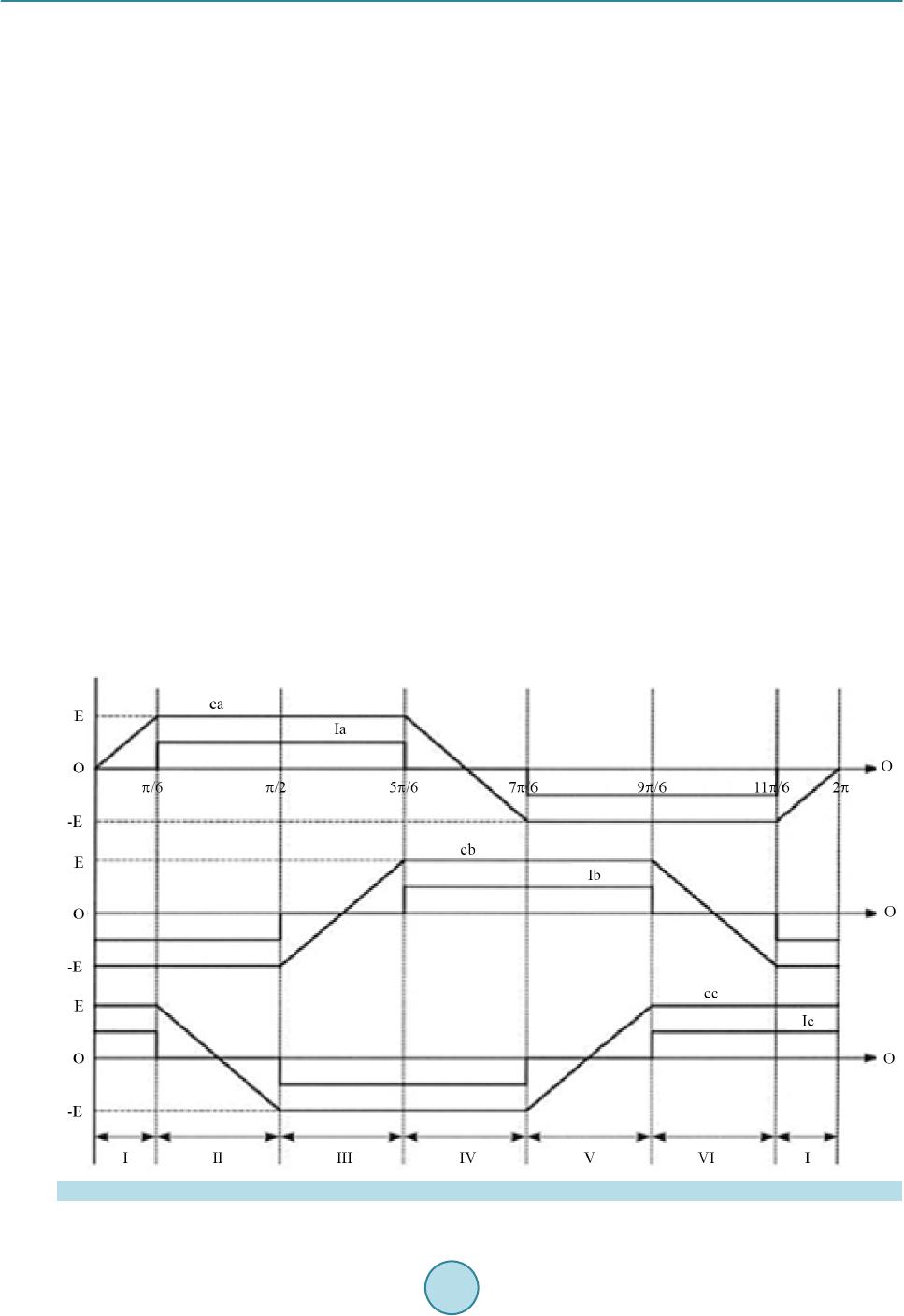
this research, the back electromotive force compensating and direct current controlling for brushless DC motor
drives analyzed and switch leg failure are avoided. In this s cheme, the pulse width modulation is applied to high
side switches of the converter. This pulse width modulation scheme can eradicate the offset voltage in the back
electromotive force signal caused by the voltage drop of the insulated b ipolar ins ulator an d also increa se syste m
efficiency by reducing the conduction loss is achieved. This proposed converter used sensorless control opera-
tion. There are no hall sensors, therefore, the system becomes robust, optimized design of the brushless DC mo-
tor achieves higher efficiency and better speed, current is formulated.
References
[1] Bo lfazl, H.N. (2008) A Novel Position Sensorless Control of a Four-Switch, Brushless DC Motor Drive without Phase
Shifter. IEEE Transactions on Power Electronics, 23, 3079-3087. http://dx.doi.org/10.1109/TPEL.2008.2002084
[2] Young-Kuk, L., Tae-Hyung, K. and Ehsani, M. (2003) On the Feasibility of Four-Switch Three-Phase Brushless DC
Motor Drives for Lo w Cost Co mmercial Appl ications : Topology and Control. IEEE Transactions on Power Electron-
ics, 18, 164-172. http://dx.doi.org/10.1109/TPEL.2002.807125
[3] Lin, C.-K., Yu, J.-T., Fu, L.-C. and Liu, T.-H. (2012) A Sensorless Position Control for Four-Switch Three-Phase In-
verter-Fed Interior Permanent Magnet Synchronous Motor Drive Systems. Proceeding of the IEEE/ASME Internation-
al Conference on Advanced Intelligent Mechatronics (AIM), 1036-1041.
[4] Adaur ia, Y., Patel, A.N., Patel, V. and Patel, J. ( 20 12) Simulation and Analysis of Three Phas e Voltage So urce Inverter
Using Four Semiconductor Swi t ches. Proceeding of the Engineering Nirma University International Conference on
Engineering (NUiCONE), Ahmedabad, 1-1 4.
[5] An, Q.T., Sun, L., Zhao, K. and Jahns, T.M. (2010) Scalar PWM Algorithms for Four-Switch Three-Phase Inverters.
Electro nics Lett ers , 46, 900 -902.
[6] Elt rao de Ro ssiter Correa, M ., Jacobin a, C.B., Cabr al da Silva, E.R. and Lima, A.M.N. (2006) A General PWM Strat-
egy for Four-Switch Thre e-Phase Inverters. IEEE Trans ac tions on Pow e r Ele c t roni c s , 21, 1618-1627.
http://dx.doi.org/10.1109/TPEL.2006.882964
[7] Xia, H.L., Li, Z.Q. and S hi, T.N. (2009) A Control Strategy for Four-Switch Thre e-Phase Bru shless DC Motor Using
Single Current Sensor. IEEE Transactions on Power Electronics, 56, 2058-2066.
[8] Lin, H.-T., Hung, C.-W. and Liu, C.-W. (2008) Position Sensor Less Control for Four-Switch Three-Phase Brushless
DC Motor Drives. IEEE Tr ansact ions on Pow e r Ele c t ronics, 23, 438-444.
http://dx.doi.org/10.1109/TPEL.2007.911782
[9] Damodharan, P. and Vasudevan, K. (2010) Sensor Less Brushless DC Mo tor Dri ve Based on the Zero -C rossin g Detec-
tion of Back Electromot ive Fo rce (E MF) from the Lin e V oltage Di fferen ce. IEEE Transactions on Energy Conversion,
25, 661-668. http://dx.doi.org/10.1109/TEC.2010.2041781
[10] Jung, D.-H. and Ha, I.-J. (2000) Low-Cost Sensor Less Control of Brushless DC Motors Using a Frequency-Inde-
pendent Phase Shifter. IEEE Transactions on Power Electronics, 15, 748-752.
[11] El Badsi, B., Bouzidi, B. and Masmoudi, A. (2013) DTC Scheme for a Four-Switch Inverter-Fed Induction Motor
Emulating the Six-Switch Inverter Operation. IEEE Transactions on Power Electronics, 28, 3528-3538.
http://dx.doi.org/10.1109/TPEL.2012.2225449
[12] Geethu, J. and Radhakrishnan, K. (2013) Simulation of Four Switch Brushless DC Motor Drive. International Journal
of Latest Trends in Engi ne e r ing and Techno logy, 2, 100-106.
[13] Rajasek aran, P . and Van chinathan, K. (2013) Improved Performance of Four Switch Three Phase Bru shless DC Motor
Using Speed-Current Control Algorithm. International Journal of Computer Applications, 68.
[14] Hoseinpour, A. (2010) Three Phase Active Filter with Four Switching Inverter and Variable Index Modulation. Pro-
cee di ng of t he 1st Power Quality Conference (PQC), Tehran , 1-7.