 Journal of Electromagnetic Analysis and Applications, 2011, 3, 305-311 doi:10.4236/jemaa.2011.38049 Published Online August 2011 (http://www.SciRP.org/journal/jemaa) Copyright © 2011 SciRes. JEMAA 305 Radiations from an Eccentric Coated Cylinder with N Slots Muhammad A. Mushref P. O. Box 9772, Jeddah 21423, Saudi Arabia. Email: mmushref@yahoo.co.uk Received June 9th, 2011; revised July 3rd, 2011; accepted July 17th, 2011. ABSTRACT The transverse magnetic (TM) radiation characteristics are investigated for a cylind er with N infinite axial slots of ar- bitrary opening size and location. The cylinder is a thin circular conductor and coated by an eccentric material. Fields are found by applying the boundary conditions to the cylindrical wave functions. The addition theorem of Bessel func- tions is used to obtain an infinite series solution in Fourier-Bessel series form. Results are computed by shrinking the generated infinite series to a finite number of terms and compared to other available data. Numerical results in graphical forms for different values are also developed and discussed for small eccentricities. Keywords: Radiation Patterns, Slotted Cylinders, Boundary Value Analysis, Addition Theorem, Eccentricity 1. Introduction The problem of field characteristics from slotted cylin- drical structures is an important study in electromagnetic field theory and has been the focus of a number of earlier researches [1-6]. Though, previous investigations did not determine possible effects to radiations of N arbitrary sited slots with diverse opening sizes and when the con- ducting cylinder and the coating material are both eccen- tric. Silver and Saunders derived expressions for the exter- nal field produced by a slot of arbitrary shape in 1950. The far field was determined by applying the method of steepest decent to the Fourier integrals in the solution [1]. The results obtained were also applied by Bailinin 1955 to the cases of narrow-width hal-wavelength slots in infi- nite cylinders with large radii [2]. Hurd derived the ra- diation patterns of an axial slot in a dielectric coated cir- cular cylinder and made some comparisons with experi- mental results in 1956 [3]. Additionally, Wait and Mi- entka presented the fields produced by an arbitrary slot on a circular cylinder with a cocentric dielectric coating in 1957. The far zone expressions were developed using a saddle-point method applied to the derived integrals [4]. In 2009, the transverse electric patterns are investigated for a cylinder with N axial slots of arbitrary opening size and position [5]. The transverse magnetic fields are then considered for a dielectric-coated metallic-cylinder with two arbitrary axial slots in 2010 [6]. 2. Mathematical Formulation Electromagnetic problems with cylindrical structures are typically better solved in cylindrical coordinates. The problem stated in this paper is solved in the two dimen- sional circular cylindrical coordinate system with (r, ). As illustrated in Figure 1, the global coordinate system (r, ) is defined at the center of the dielectric coating material and the local coordinate system (rc, c) is de- fined at the center of the slotted metallic cylinder. The center of the local coordinate system is situated at x = d with respect to the global coordinate system. In this paper, the transverse magnetic (TM) character- istics are found for N infinite axial slots in a circular me- tallic cylinder covered by a dielectric material as shown in Figure 1. The cylinder is assumed to be a thin perfect electric conductor with radius a and with infinite extent along the z-axis. On the cylinder surface N slots are axi- ally opened with an angular apertures of 2 1, 2 2, 2 3, , 2 N located at s1, s2, s3, , sN respectively with respect to the x-axis. The cylinder is entirely covered by an eccentric dielectric layer with radius b and assumed to be homogenous, linear, and isotropic and characterized by permittivity and permeability . The region out of the coating material for all r > b and 0 2 is as- sumed to be free space with 0 and 0. As shown in Fig- ure 1, the dielectric material and free space are consid- ered as region I and region II respectively. Formulation starts by solving the Helmholtz scalar  Radiations from an Eccentric Coated Cylinder with N Slots 306 Region I , b a Region II 0 , 0 Y d Y c s2 2 2 2 N sN s1 2 1 Figure 1. Cross sectional view of the structure. wave equation in the circular cylindrical coordinate sys- tem in r and . Going after the separation of variables method, the solution is a Bessel or Hankel function in r multiplied by a complex exponential in . The structure shown in Figure 1 requires the electric field to be repre- sented by a Fourier-Bessel exponential series. In region I, this is represented by a summation of a harmonic func- tion multiplied by Bessel functions as [5,6]: Iin nnnn n n EeJkrYkr A (1) In region II, the electric field radiates from the struc- ture and therefore the Hankel function is assumed and multiplied by a harmonic function as [7,8]: II (2) 0 in n n EeHkr n A (2) where n, n and An are unknown coefficients and i = 1. k and k0 are the dielectric coating and free space wave numbers respectively given by k = 2/ and is the wavelength. Jn(x) and Yn(x) are Bessel functions of the first and the second type respectively with order n and argument x. (2) n (x) is the outgoing Hankel function of the second type with order n and argument x. 3. Analytical Solution The boundary conditions are applied to find n, n and An coefficients. From the geometry of the structure shown in Figure 1, the boundary conditions with respect to the global coordinate are continuity of both tangential elec- tric Ez and magnetic H fields for all at r = b, that is: III at and 02π zz EE rb (3) III at and 02πHH rb (4) where H is derived from Maxwell’s equations as z iE r [5,6]. Equations (3) and (4) can be solved using the or- thogonality of the complex exponential functions to get: (2) 0nn nnn kbYkbHk b (5) (2) 0nnnnr n kbYkbeHk b (6) where rrr e and the prime notation designates differentiation with respect to the argument. Equations (5) and (6) are then solved to find n and n as: (2) 0 (2) 0 π 2 nn n rn n HkbYkb kb eHkbY kb (7) (2) 0 (2) 0 π 2 nn n rn n HkbJkb kb eHkb Jkb (8) The third boundary condition can be expressed in the local coordinate system. At rc = a the tangential electric field vanishes in region I for all values of c except at the slots where it has a value of: Iπ cos 2 csL zoLL EE d d (9) for rc = a, | c – sL| < L and L = 1, , N. The addition theorem of Bessel functions is given by [9,10]: () 1 c c im m im p pmpcpc ip pmpp cc Tkre TkrJkde r TkdJkre r (10) where Tm(x) can be Jm(x) or Ym(x) and m and p are inte- gers. By applying the theorem in Equation (10) to the boundary condition in Equation (9), the outcome can be simplified to be: 222 1 1 2cos π4 sL mn mm nn n mn mn nmn m Nim oL LL LL JkaYka A kdY kd Jkdad Jkaad Eme m (11) For small values of L, cos(m L) ≈ 1 and Equation (11) can be simplified to: Copyright © 2011 SciRes. JEMAA  Radiations from an Eccentric Coated Cylinder with N Slots307 222 1 1 2π4 sL mn mm nn n mn mn nmn m Nim oL L LL JkaYka A kdY kd Jkdad Jka ad Ee m m (12) For small values of d the summation quickly con- verges and thus Equation (12) can be further simplified if expressed in matrix form. Therefore, the coefficients An can be found as: 1 , 11 nnmm n nm AZ f (13) where Zn.m is the second factor in the left side of Equation (12) and fm is the right side of the same equation. The matrix ,nm mn in Equation (13) is a non-singular square matrix. Z The asymptotic expression of the Hankel function can be used in Equation (2). Hence, the radiated field can be estimated at a far point as [3,6]: 0π4 II 0 2 π ikr z EeP kr (14) where P( ) is the far radiated field pattern given by: nin n n PiAe (15) The antenna gain and the aperture conductance per unit length 0 are two other major quantities in the study of the antenna characteristics. By Equations (13) and (15) both can be respectively found as in reference [11] to be: 2 2 π 2n n P G (16) 2 02 1 4n n aN oL L G V (17) where VoL is the voltage across the slot equals EoL as in Equation (9) [8,9]. 4. Numerical Analysis It is essential to confirm the correctness of the expres- sions derived before obtaining the numerical results for the consequences of the slots’ arbitrary sizes and loca- tions. Several graphical results are computed and also judged against other curves in reference [11] for a slot size of 0 = /100. The results achieved are only calcu- lated for values of n from –25 to 25 of the series pro- duced in the solution due to the fast convergence of the summation. The produced field patterns are normalized to the curves of zero eccentricity to simplify investiga- tions and recognize the variations that may happen when N axial slots of arbitrary size and position exist with ec- centricity. Equation (12) is expressed as a series over n from –∞ to +∞ which can produce infinite matrices in Equation (13). This series quickly converges for small values of d and can be numerically solved by reduction to develop finite matrices. In contrast, for larger values of d the physical size of the antenna structure shown in Figure 1 is bigger and additional terms in the summation are re- quired [12]. Therefore, the numerical evaluations are computed for small eccentricities in order to smooth the progress of the series expansion. The antenna gain in Equation (16) compared to refer- ence [9] is shown in Figure 2(a) versus the coating thickness at = 0 for N = 1, Eo1 = 1, s1 = 0, 2 1 = 0, d = 0.001 0, / 0 = 4, / 0 = 1 and a = 2 0. In addition, the aperture conductance per unit length 0 in Equation (17) is shown in Figure 2(b) versus the coating thickness for N = 1, Eo1 = 1, s1 = 0, 2 1 = 0, d = 0.001 0, / 0 = 4, / 0 = 1and a = 2 0 assessed against the same results in reference [11]. As expected, the curves establish perfect agreements and the calculated results confirm every in- dication of accuracy. Additionally, convergence tests cla- rify that a sufficient number of terms in the infinite series is applied. The far radiated patterns are better investigated in po- lar coordinates due to the general shape of the proposed structure shown in Figure 1. As in most references, the cylinder radius and the coating thickness are assumed to be a = 0.358 0 and b = 0.4217 0 respectively. Besides, the number of slots considered in all patterns computa- tions is N = 3 with three values of eccentricities as d = 0 0, 0.02 0 and 0.06 0 respectively. Also, the voltages across all slots are assumed as EoL = 1 where L is the slot number. All calculated radiation patterns are normalized to the maximum value of the zero eccentric case, d = 0. 5. Results and Discussions Figure 3 illustrates the radiation patterns for s1 = 0, s2 = /2, s3 = and 2 1 = 2 2 = 2 3 = 0. In Figure 3(a), the fields are computed for / 0= 2.56 and / 0= 1. Field patterns are symmetric around the y-axis for d = 0 0 but new lobes may appear as eccentricity increases as seen for d = 0.06 0. Figure 3(b) shows the radiation patterns for / 0= 1 and / 0= 4. Symmetry is also noticed for d = 0 around the y-axis and different lobes are produced when d is changed. A dditionally, Figure 4 shows the radiation patterns for Copyright © 2011 SciRes. JEMAA  Radiations from an Eccentric Coated Cylinder with N Slots Copyright © 2011 SciRes. JEMAA 308 22.075 2.15 2.2252.3 2 0 2 4 6 8 22.075 2.15 2.2252.3 0 0.02 0.04 0.06 0.08 0.1 0.12 (a) (b) Figure 2. (a) Antenna gain in dB versus coating thic kness for / 0 = 4, / 0 = 1 and a = 2 0, —— reference [9], – – – calculated at = 0 for Eo1 = 1, N = 1, s1 = 0, 2 1 = 0, and d = 0.001 0; (b) Aperture conductance in millisiemens versus c oating thickness for / 0 = 4, / 0 = 1 and a = 2 0, —— reference [9], – – – calculated for Eo1 = 1, N = 1, s1 = 0, 2 1 = 0, and d = 0.001 0. 0 30 60 90 120 150 180 210 240 270 300 330 .. 0 30 60 90 120 150 180 210 240 270 300 330 .. (a) (b) Figure 3. Radiation patterns for N = 3, s1 = 0, s2 = /2, s3 = , 2 1 = 2 2 = 2 3 = 0, a = 0.358 0 and b = 0.4217 0 —— d = 0 0, d = 0.02 0, – – – d = 0.06 0. (a) / 0 = 2.56, / 0 = 1; (b) / 0 = 1, / 0 = 4. s1 = 0, s2 = /2, s3 = and 2 1 = 0, 2 2 = 2 0 and 2 3 = 3 0. In Figure 4(a), the fields are computed for / 0= 2.56 and / 0= 1. Lobes on the left side are greater due to the larger size of the slot at that location where they may also increase as eccentricity increases. The same under- standing can be accepted for the radiation patterns shown in Figure 4(b) for / 0 = 1 and / 0 = 4. Also, Figure 5 illustrates the radiation patterns for s1 = 0, s2 = 2/3, s3 = 4/3 and 2 1 = 2 2 = 2 3 = 0. In Figure 5(a), the fields are computed for / 0 = 2.56 and / 0 = 1. Symmetry is very clear around the x-axis for all values of d with the maximum lobe at = . Figure 5(b) shows the radiation patterns for / 0 = 1 and / 0 = 4. Symmetry is also noticed around the x-axis but with lar- ger lobes at = 0 as d increases. The last computed radiation patterns are shown in Fig- ure 6 for s1 = 0, s2 = 2/3, s3 = 4/3 and 2 1 = 0, 2 2 = 2 0 and 2 3 = 3 0. In Figure 6(a), the fields are plotted for / 0 = 2.56 and / 0 = 1. No symmetry is noticed due to the different sizes of the slots. Figure 6(b) shows the radiation patterns for / 0 = 1 and / 0 = 4 where the larger lobes are in the place of larger slots. From the above, symmetry of the radiation patterns and size of the lobes are greatly affected by the location  Radiations from an Eccentric Coated Cylinder with N Slots309 0 30 60 90 120 150 180 210 240 270 300 330 .. 0 30 60 90 120 150 180 210 240 270 300 330 .. (a) (b) Figure 4. Radiation patterns for N = 3, s1 = 0, s2 = /2, s3 = , 2 1 = 0, 2 2 = 2 0, 2 3 = 3 0, a = 0.358 0 and b = 0.4217 0, —— d = 0 0, d = 0.02 0, – – – d = 0.06 0. (a) / 0 = 2.56, / 0 = 1; (b) / 0 = 1, / 0 = 4. 0 30 60 90 120 150 180 210 240 270 300 330 .. 0 30 60 90 120 150 180 210 240 270 300 330 .. (a) (b) Figure 5. Radiation patterns for N = 3, s1 = 0, s2 = 2/3, s3 = 4/3, 2 1 = 2 2 = 2 3 = 0, a = 0.358 0 and b= 0.4217 0, —— d = 0 0, d = 0.02 0, – – – d = 0.06 0. (a) / 0 = 2.56, / 0 = 1; (b) / 0 = 1, / 0 = 4. and the size of each slot and the eccentricity of the coat- ing. Moreover, the gain in dB at = 0 is plotted in Figure 7 for N = 3, s1 = 0, 2 1 = 0, 2 2 = 2 0 and 2 3 = 3 0. Figure 7(a) shows the gain versus the coating thickness for a = 2 0, d = 0 0, s2 = /2, s2 = , / 0 = 4, / 0 = 1, / 0 = 1 and / 0 = 4 and also for s2 = 2/3, s2 = 4, / 0 = 4, / 0 = 1, / 0 = 1 and / 0 = 4. As noticed, the gain is almost constant at less than 0.9 up to b = 2.15 0 but greatly changed for larger coating thickness values. The gain versus eccentricity is also plotted in Figure 7(b) for a = 0.9 0, b = 2.1 0, s2 = /2, s2 = , / 0 = 4, / 0 = 1, / 0 = 1 and / 0 = 4 and also for s2 = 2/3, s2 = 4, / 0 = 4, / 0 = 1, / 0 = 1 and / 0 = 4. The gain does not change much for eccentricities of 0 ≤ d ≤ 0.6 but different peaks may occur for d = 0.75 0 and d = 1 0. The aperture conductance is shown in Figure 8 for N = 3, s1 = 0, 2 1 = 0, 2 2 = 2 0 and 2 3 = 3 0. Figure 8(a) shows the aperture conductance versus the coating thickness for a = 2 0, d = 0 0, s2 = /2, s2 = , / 0 = 4, Copyright © 2011 SciRes. JEMAA  Radiations from an Eccentric Coated Cylinder with N Slots 310 / 0 = 1, / 0 = 1 and / 0 = 4 and also for s2 = 2/3, s2 = 4, / 0 = 4, / 0 = 1, / 0 = 1 and / 0 = 4. The conductance shows several peaks for b > 2.2 0. The ap- erture conductance versus eccentricity is also plotted in Figure 8(b) for a = 0.9 0, b = 2.1 0, s2 = /2, s2 = , / 0 = 4, / 0 = 1, / 0 = 1 and / 0 = 4 and also for s2 = 2/3, s2 = 4, / 0 = 4, / 0 = 1, / 0 = 1 and / 0 = 4. The conductance is nearly less than 1 millisiemens up to d = 0.7 0 but different peak values appear for larger ec- centricities. 6. Conclusions An analytical solution was derived for the problem of N infinite axial slots in a circular cylinder covered with an eccentric dielectric coating material. The TM case was considered based on the boundary value method and the radiated fields were represented in terms of an infinite series of cylindrical waves. The solution explained the 0 30 60 90 120 150 180 210 240 270 300 330 . 0 30 60 90 120 150 180 210 240 270 300 330 . (a) (b) Figure 6. Radiation patterns for N = 3, s1 = 0, s2 = 2 /3, s3 = 4/3, 2 1 = 0, 2 2 = 2 0, 2 3 = 3 0, a = 0.358 0 and b= 0.4217 0, —— d = 0 0, d = 0.02 0, – – – d = 0.06 0. (a) / 0 = 2.56, / 0 = 1; (b) / 0 = 1, / 0 = 4. 22.075 2.15 2.2252.3 0 0.9 1.8 2.7 3.6 4.5 00.25 0.5 0.751 0 2 4 6 8 10 12 (a) (b) Figure 7. Antenna gain in dB versus coating thickness at = 0 for N = 3, s1 = 0, 2 1 = 0, 2 2 = 2 0 and 2 3 = 3 0. (a) a = 2 0, d = 0 0, s2 = /2, s2 = , (—— / 0 = 4, / 0 = 1), ( / 0 = 1, / 0 = 4), s2 = 2/3, s2 = 4, ( – – – / 0 = 4, / 0 = 1), (– · – · – / 0 = 1, / 0 = 4); (b) a = 0.9 0, b = 2.1 0, s2 = /2, s2 = , (—— / 0 = 4, / 0 = 1), ( / 0 = 1, / 0 = 4), s2 = 2/3, s2 = 4, (– – – / 0 = 4, / 0 = 1), (– · – · – / 0 = 1, / 0 = 4). Copyright © 2011 SciRes. JEMAA  Radiations from an Eccentric Coated Cylinder with N Slots311 22.075 2.15 2.2252.3 0 0.32 0.64 0.96 1.28 1.6 00.25 0.5 0.751 0 1.25 2.5 3.75 5 6.25 7.5 (a) (b) Figure 8. Aperture conductance in millisimens versus coating thickness for N = 3, s1 = 0, 2 1 = 0, 2 2 = 2 0 and 2 3 = 3 0. (a) a = 2 0, d = 0 0, s2 = /2, s2 = , (—— / 0 = 4, / 0 = 1), ( / 0 = 1, / 0 = 4), s2 = 2/3, s2 = 4, (– – – / 0 = 4, / 0 = 1), (– · – · – / 0 = 1, / 0 = 4); (b) a = 0.9 0, b = 2.1 0, s2 = /2, s2 = , (—— / 0 = 4, / 0 = 1), ( / 0 = 1, / 0 = 4), s2 = 2/3, s2 = 4, (– – – / 0 = 4, / 0 = 1), (– · – · – / 0 = 1, / 0 = 4). effects of the proposed additional slots in arbitrary loca- tions with eccentricity to the far field patterns. Possible influences that can take place to the antenna gain and the aperture conductance were presented and discussed. REFERENCES [1] S. Silver and W. Saunders, “The External Field Produced by a Slot in an Infinite Circular Cylinder,” Journal of Ap - plied Physics, Vol. 21, No. 5, February 1950, pp. 153- 158. doi:10.1063/1.1699615 [2] L. L. Bailin, “The Radiation Field Produced by a Slot in a Large Circular Cylinder,” IRE Transactions—Antennas and Propagation, Vol. AP-3, No. 3, July 1955, pp. 128-137. doi:10.1109/TAP.1955.1144301 [3] R. A. Hurd, “Radiation Patterns of a Dielectric-Coated Axially Slotted Cylinder,” Canadian Journal of Physics, Vol. 34, No. 7, 1956, pp. 638-642. doi:10.1139/p56-072 [4] J. Wait and W. Mientka, “Slotted-Cylinder Antenna with a Dielectric Coating,” Journal of Research of the Na- tional Bureau of Standards, Vol. 58, No. 6, June 1957, pp. 287-296. [5] M. A. Mushref, “Radiation from an Eccentric Coated Cylinder with Slots of Arbitrary Sizes and Positions,” Progress in Electromagnetics Research B, Vol. 11, 2009, pp. 55-78. doi:10.2528/PIERB08100305 [6] M. A. Mushref, “Electromagnetic Radiation from a Coated Cylinder with Two Arbitrary Axial Slots,” High Frequency Electronics, Vol. 9, No. 2, February 2010, pp. 47-54. [7] L. Shafai, “Radiation from an Axially Slot Antenna Coated with a Homogeneous Material,” Canadian Jour- nal of Physics, Vol. 50, No. 23, 1972, pp. 3072-3077. doi:10.1139/p72-400 [8] M. A. Mushref, “TM Radiation from an Eccentric Dielec- tric Coated Cylinder with Two Infinite Slots,” Journal of Electromagnetic Waves and Applications, Vol. 19, No. 5, 2005, pp. 577-590. doi:10.1163/1569393053305044 [9] W. C. Chew, “Waves and Fields in Inhomogeneous Me- dia,” IEEE, New York, 1995. [10] R. F. Harrington, “Time-Harmonic Electromagnetic Fields,” IEEE, New York, 2001. doi:10.1109/9780470546710 [11] J. Richmond, “Axial Slot Antenna on a Dielectric-Coated Elliptic Cylinder,” IEEE Transactions on Antennas and Propagation, Vol. 37, No. 10, October 1989, pp. 1235- 1241. doi:10.1109/8.43531 [12] M. A. Mushref, “Matrix Solution to Electromagnetic Scattering by a Conducting Cylinder with an Eccentric Metamaterial Coating,” Journal of Mathematical Analysis and Applications, Vol. 332, No. 1, 2007, pp. 356-366. doi:10.1016/j.jmaa.2006.10.039 Copyright © 2011 SciRes. JEMAA
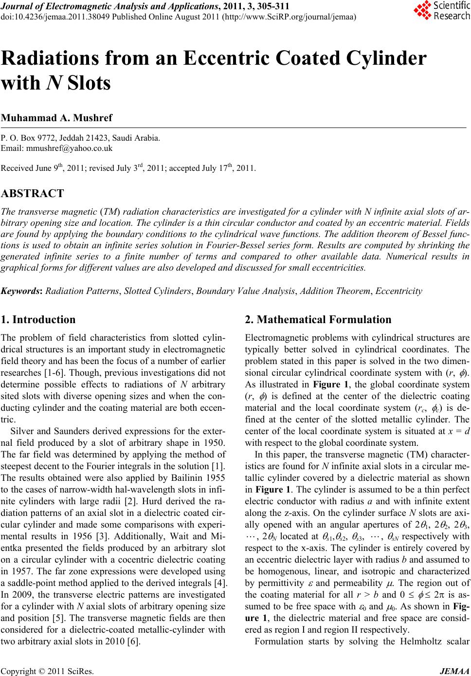
|