Interaction of 8 MeV Electron beam with P31 Bombyx mori Silk Fibers
832
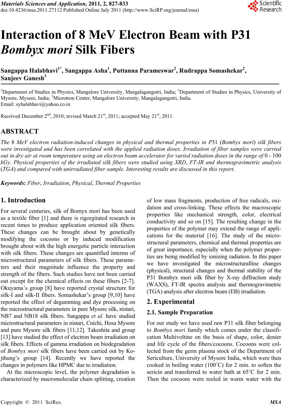
100 200 300 400 500 600 700 800
0
20
40
60
80
100
100 kGy
50 kGy
0 kGy
Weight loss (%)
Temperature (oC)
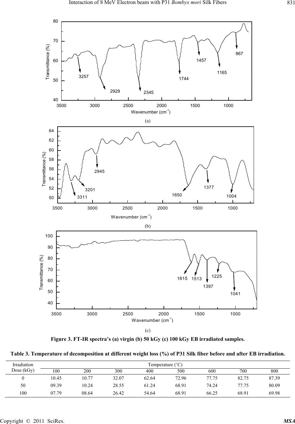
Figure 4. TGA thermograms of (a) virgin (b) 50 kGy (c) 100
kGy EB irradiated samples.
cross-linking of P31 silk fiber due to EB irradiation.
6. Acknowledgements
The authors are thankful to University Grant Commis-
sion, New Delhi, Govt of India, for providing financial
assistance through a project F. No. 33-14/2007 (SR). The
authors are also thankful to STIC Cochin University for
extending the experimental facilities.
REFERENCES
[1] D. Lance Miller, S. Putthanarat and W. W. Adoms, “In-
vestigation of the Nano Fibrillar Morphology in Silk Fi-
ber by Small Angle X-Ray Scattering and Atomic Force
Microscopy,” International Journal of Biological Mac-
romolecules, Vol. 24, No. 2, March 1999, pp. 159-165.
doi:10.1016/S0141-8130(99)00024-0
[2] N. Mohanthy, H. K. Das, P. Mohanthy and E. Mohanthy,
“Modification of Muga Silk by Methyl-Methacrylate.II,”
Journal of Macromolecular Science, Vol. 32, 1995, pp.
1103-1108. doi:10.1080/10601329508019151
[3] Y. Kavahara, M. Shioya and A. Takaku, “Influence of
Swelling of Non-Crystalline Regions in Silk Fibers on
Modification with Methacrylamide,” Journal of Applied
Polymer Science, Vol. 59, 1996, pp. 51-56.
doi:10.1002/(SICI)1097-4628(19960103)59:1<51::AID-
APP8>3.0.CO;2-L
[4] G. Freddi, M. R. Massafra, S. Beretta, S. Shibata, Y.
Gotch, H. Yasui and M. T.Sukuda, “Structure and Prop-
erties of Bombyx Mori Silk Fibers Grafted with
Methacrylamide (MAA) and 2-Hydroxy Ethylmethacry-
late (HEMA),” Journal of Applied Polymer Science, Vol.
60, 11, 1996, pp.1867-1876.
doi:10.1002/(SICI)1097-4628(19960613)60:11<1867::AI
D-APP10>3.0.CO;2-Z
[5] M. Tsukuda, M. Obo, H. Kato, G. Freddi and F. Zenetti,
“structure and Dyeability of Bombyxmori Silk Fibers
with Different Filament Sizes,” Journal of Applied Poly-
mer Science, Vol. 60, No. 10, 1996, pp. 1619-1627.
doi:10.1002/(SICI)1097-4628(19960606)60:10<1619::AI
D-APP14>3.0.CO;2-#
[6] M. Tsukuda, Y. Gotch, M. Nagura, N. Minoura, N. Kasai
and G. Freddi, “Structural Changes of Silk Fibroin Mem-
brance Induced by Immersion in Methanol Aqueous So-
lution,” Journal of Polymer Science (B), Vol. 32, 1994,
pp. 961-968. doi:10.1002/polb.1994.090320519
[7] H. Somashekarappa, N. Selvakumar, V. Subramaniam
and R. Somashekar, “Structure-Property Relation in Va-
rieties of Acid Dye Processed Silk Fibers,” Journal of
Applied Polymer Science, Vol. 59, 1996, pp. 1677-1683.
doi:10.1002/(SICI)1097-4628(19960314)59:11<1677::AI
D-APP3>3.0.CO;2-L
[8] K. Okuyama, K. Takanashi, Y. Nakajima, Y. Hasegawa,
K. Hirabayashi and N. Nishi, “Analysis of Silk I Structure
by X-Ray and Electron Diffraction Method,” Journal of
Service Science, Vol. 57, 1988, pp. 23-30.
[9] H. Somashekarappa, V. Annadurai, Sangappa, G. Subra-
manya and R. Somashekar, “Structure-Property Relation
in Varities of Acid Dye Processed Silk Fibers,” Materials
Letters, Vol. 53, No. 6, 2002, pp. 415-420.
doi:10.1016/S0167-577X(01)00517-1
[10] H. Somashekarappa, G. S. Nadgir, T. H. Somashekar, J.
Prabhu and R. Somashekar, “WAXS Studies on Silk Fi-
bers Treated with Acid (Blue) and Metal Complex
(Brown) Dyes,” Polymer, Vol. 39, No. 1, 1998, pp. 209-
213. doi:10.1016/S0032-3861(97)00220-6
[11] Sangappa, K. Okuyama and R. Somashekar, “Stain
–Tensor Components, Crystallite Shape and Their Effects
on Crystalline Structure in Silk I,” Journal of Applied
Polymer Science, Vol. 91, 2004, pp. 3045-3058.
[12] Sangappa, S. S. Mahesh and R. Somashekar, “Crystal
Structure of Raw Pure Mysore Silk Fiber Based on
(Ala-Gly) 2–Ser–Gly Peptide Sequence Using Linked-
Atom-Least-Squares method,” Journal of Bioscience, Vol.
30, No. 2, 2005, pp. 259-268. doi:10.1007/BF02703707
[13] H. Takeshita, K. Ishida, Y. Kamiishi, F. Yoshii and T.
Kume, “Production of Fine Powder from Silk by Radia-
tion,” Macromolecular Materials and Engineering, Vol.
283, 2000, pp.126-131.
doi:10.1002/1439-2054(20001101)283:1<126::AID-MA
ME126>3.0.CO;2-#
[14] A. Kojthung, P. Meesilpa, B. Sudatis, L. Treeratanapi-
boon, R. Udomsangpetch and B. Oonkhanond, “Effects of
Gamma Irradiation on Biodegradation of Bombyx Mori
Silk Fibroin,” International Biodeterioration and Bio-
degradation, Vol. 62, No. 4, 2008, pp. 487-490.
doi:10.1016/j.ibiod.2007.12.012
[15] G. Wang, G. Pan, L. Dow, S. Jiang and Q. Dai, “Proton
Beam Modification of Isotactic Polypropylene,” Nuclear
Instruments and Methods in Physics Research Section B,
Vol. 27, No. 3, 1987, pp. 410-416.
doi:10.1016/0168-583X(87)90521-0
[16] Sangappa, S. Asha, T. Demappa, Ganesh Sanjeev, P.
Parameswara and R. Somashekar, “Spectroscopic and
Thermal Studies of 8 MeV Electron Beam Irradiated
HPMC Films,” Nuclear Instruments and Methods in
Copyright © 2011 SciRes. MSA