 Circuits and Systems, 2011, 2, 225-236 doi:10.4236/cs.2011.23032 Published Online July 2011 (http://www.SciRP.org/journal/cs) Copyright © 2011 SciRes. CS Fast Signed-Digit Multi-operand Decimal Adders Jeff Rebacz, Erdal Oruklu, Jafar Saniie Department of Electrical and Computer Engineering, Illinois Institute of Technology, Chicago, USA E-mail: erdal@ece.iit.edu Received April 14, 2011; revised May 22, 2011; accepted May 29, 2011 Abstract Decimal arithmetic is desirable for high precision requirements of many financial, industrial and scientific applications. Furthermore, hardware support for decimal arithmetic has gained momentum with IEEE 754- 2008, which standardized decimal floating-point. This paper presents a new architecture for two operand and multi-operand signed-digit decimal addition. Signed-digit architectures are advantageous because there are no carry-propagate chains. The proposed signed-digit adder reduces the critical path delay by parallelizing the correction stage inherent to decimal addition. For performance evaluation, we synthesize and compare multiple unsigned and signed-digit multi-operand decimal adder architectures on 0.18 μm CMOS VLSI technology. Synthesis results for 2, 4, 8, and 16 operands with 8 decimal digits provide critical data in de- termining each adder’s performance and scalability. Keywords: Computer Arithmetic, Decimal Arithmetic, Signed-Digit, Multi-operand Adder, BCD 1. Introduction Translating a decimal fraction into a finite floating-point representation is prone to losing precision as a result of rounding errors. In almost all financial settings, decimal arithmetic is desired to guarantee balances are calculated correctly and lawfully. Some industrial and scientific applications require high-precision decimal arithmetic as well. Software packages have been available for most programming languages so that decimal numbers could be evaluated with decimal arithmetic to avoid error [1,2]. IBM recently departed from this software solution by incorporating a decimal floating-point arithmetic unit in the Power6 [3] and z10 processors [4]. A compelling reason to do such is a report [5] showing that 55% of the numbers stored in the databases of 51 major organiza- tions are decimal. One study shows that for a set of five benchmarks, a 1.3 to 12.8 speedup factor was obtained by simulating a processor using virtual decimal arithme- tic hardware against software routines [6]. Applications that spend a large proportion of the time consuming decimal calculation stand to benefit from hardware-based decimal operations. Therefore, research into decimal arithmetic has gained momentum. Decimal renditions of binary carry-save [7,8] and carry-lookahead adders [9-11] have been proposed. Decimal floating-point addition is treated in [12-14]. New decimal multipliers [15-18] and dividers [19-21] have also been proposed. In [17], new decimal encodings improve the latency and area for de- cimal partial product generation and reduction for multi- plication. Similarly, in [22], a new redundant digit set is used with special encodings called two-valued digits (twits), resulting in a faster implementation of both addi- tion and subtraction. The main motivation behind this paper is to introduce a new signed-digit architecture and objectively compare it with signed and unsigned digit adders. Signed-digit decimal adders have the benefit of carry-free addition although a carry-propagate adder must be used to trans- form the signed-digit sum into an unsigned sum. In the next two sections, we will present the theory of decimal encodings and signed-digit decimal numbers. In the sub- sequent sections, brief descriptions of other adders are given: the nonspeculative multi-operand adder [7], mixed binary and BCD adder [23], reduced delay BCD adder [10], dynamic decimal CLA [11], Svoboda adder [24], speculative signed-digit adder [25], decimal carry-free adder [26] and Redundant Binary Coded Decimal (RBCD) adder [27,28]. Then, the proposed method for signed-digit addition is discussed. A constant addition technique will be applied to both the correction step in signed-digit decimal addition and conversion to binary- coded decimal (BCD). Multi-operand decimal addition based on signed-digit addition will follow. Finally, the synthesis results will be discussed. The notation used throughout this paper is as follows: 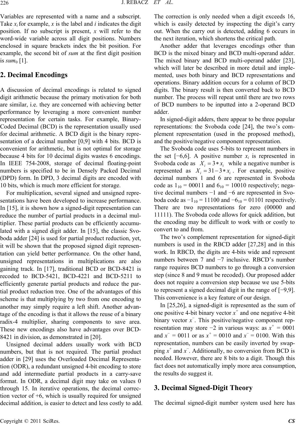 226 J. REBACZ ET AL. Variables are represented with a name and a subscript. Take xi for example, x is the label and i indicates the digit position. If no subscript is present, x will refer to the word-wide variable across all digit positions. Numbers enclosed in square brackets index the bit position. For example, the second bit of sum at the first digit position is sum0 [1]. 2. Decimal Encodings A discussion of decimal encodings is related to signed digit arithmetic because the primary motivation for both are similar, i.e. they are concerned with achieving better performance by leveraging a more convenient number representation for certain tasks. For example, Binary- Coded Decimal (BCD) is the representation usually used for decimal arithmetic. A BCD digit is the binary repre- sentation of a decimal number [0,9] with 4 bits. BCD is convenient for arithmetic, but is not optimal for storage because 4 bits for 10 decimal digits wastes 6 encodings. In IEEE 754-2008, storage of decimal floating-point numbers is specified to be in Densely Packed Decimal (DPD) form. In DPD, 3 decimal digits are encoded with 10 bits, which is much more efficient for storage. For multiplication, several signed and unsigned repre- sentations have been developed to increase performance. In [15], it is shown how a signed-digit representation can reduce the number of partial products in a decimal mul- tiplier. These partial products can be efficiently accumu- lated with a signed digit adder. In [15], the classic Svo- boda adder [24] is used for partial product reduction, yet, it will be shown that the proposed signed digit represen- tation can yield better performance. On the other hand, unsigned representations in multiplications are also gaining track. In [17], traditional BCD or BCD-8421 is recoded to BCD-5421, BCD-4221 and BCD-5211 to efficiently generate partial products and reduce the par- tial product reduction tree. One of the advantages of this scheme is that multiplying by two from one encoding to another may simply require a left shift. Another advan- tage of the encoding is that it allows the reuse of a binary radix-4 multiplier, sharing components to save area. These new encodings also have advantages over BCD- 8421 in division, as demonstrated in [20]. Unsigned decimal adders usually work with BCD numbers, but that is not required. The partial product adder in [29] uses the Overloaded Decimal Representa- tion (ODR), a redundant unsigned 4-bit encoding to store and add intermediate partial products in a carry-save format. In ODR, a decimal digit may take on values 0 through 15. In iterative operations, the decimal correc- tion vector of +6, which is usually required for unsigned decimal addition, is easier to detect and less costly to add. The correction is only needed when a digit exceeds 16, which is easily detected by inspecting the digit’s carry out. When the carry out is detected, adding 6 occurs in the next iteration, which shortens the critical path. Another adder that leverages encodings other than BCD is the mixed binary and BCD multi-operand adder. The mixed binary and BCD multi-operand adder [23], which will later be described in more detail and imple- mented, uses both binary and BCD representations and operations. Binary addition occurs for a column of BCD digits. The binary result is then converted back to BCD number. The process will repeat until there are two rows of BCD numbers to be inputted into a 2-operand BCD adder. In signed-digit adders, there appear to be three popular representations: the Svoboda code [24], the two’s com- plement representation (used in the proposed method), and the positive/negative component representation. The Svoboda code uses 5-bits to represent numbers in the set [−6,6]. A positive number xi is represented in Svoboda code as 3 ii x 31 3 i while a negative number is represented as i x . For example, positive decimal numbers 1 and 6 are represented in Svoboda code as 110 = 00011 and 610 = 10010 respectively; nega- tive decimal numbers −1 and −6 are represented in Svo- boda code as −110 = 11100 and −610 = 01101 respectively. There are two representations for zero (00000 and 11111). The Svoboda code allows for quick addition, but the encoding may be difficult to work with or costly to convert to and from. The two’s complement representation for signed-digit numbers is used in the RBCD adder [27,28] and in this work. In RBCD, the digits are 4-bits wide and represent numbers between 7 and −7 inclusive. RBCD’s number range requires BCD numbers to go through a conversion step (since 8 and 9 must be recoded). Our proposed adder does not require a conversion step because we use 5-bits to represent a signed decimal digit in the range of [−9,9]. This convenience is a key feature of our design. In [25,26], a signed-digit is represented as the sum of one positive 4-bit binary vector x+ and one negative 4-bit binary vector x−. This positive/negative component rep- resentation may store −2 in various ways: as x+ = 0001 and x− = 0011 or as x+ = 0010 and x− = 0100. With this representation, numbers can be easily inverted by swap- ping x+ and x−. Additionally, no conversion from BCD is needed. However, there are 8 bits to a digit. Though this fact does not automatically imply more area consumption, the results do suggest it. 3. Decimal Signed-Digit Theory The decimal signed-digit number system used here has Copyright © 2011 SciRes. CS 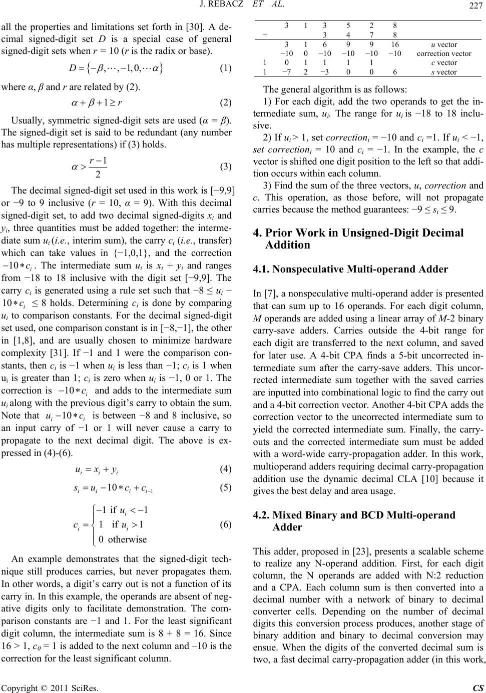 J. REBACZ ET AL. 227 all the properties and limitations set forth in [30]. A de- cimal signed-digit set D is a special case of general signed-digit sets when r = 10 (r is the radix or base). 3 13 5 2 ,,1,0,D (1) where α, β and r are related by (2). 1r (2) Usually, symmetric signed-digit sets are used (α = β). The signed-digit set is said to be redundant (any number has multiple representations) if (3) holds. 1 2 r (3) The decimal signed-digit set used in this work is [−9,9] or −9 to 9 inclusive (r = 10, α = 9). With this decimal signed-digit set, to add two decimal signed-digits xi and yi, three quantities must be added together: the interme- diate sum ui (i.e., interim sum), the carry ci (i.e., transfer) which can take values in {−1,0,1}, and the correction . The intermediate sum ui is xi + yi and ranges from −18 to 18 inclusive with the digit set [−9,9]. The carry ci is generated using a rule set such that −8 ≤ ui − ≤ 8 holds. Determining ci is done by comparing ui to comparison constants. For the decimal signed-digit set used, one comparison constant is in [−8,−1], the other in [1,8], and are usually chosen to minimize hardware complexity [31]. If −1 and 1 were the comparison con- stants, then ci is −1 when ui is less than −1; ci is 1 when ui is greater than 1; ci is zero when ui is −1, 0 or 1. The correction is and adds to the intermediate sum ui along with the previous digit’s carry to obtain the sum. Note that i is between −8 and 8 inclusive, so an input carry of −1 or 1 will never cause a carry to propagate to the next decimal digit. The above is ex- pressed in (4)-(6). 10 i c 10 i c 10 i c 10 i uc iii uxy (4) 1 10 ii ii ucc (5) 1if1 1if 1 0otherwise i ii u cu (6) An example demonstrates that the signed-digit tech- nique still produces carries, but never propagates them. In other words, a digit’s carry out is not a function of its carry in. In this example, the operands are absent of neg- ative digits only to facilitate demonstration. The com- parison constants are −1 and 1. For the least significant digit column, the intermediate sum is 8 + 8 = 16. Since 16 > 1, c0 = 1 is added to the next column and –10 is the correction for the least significant column. 8 + 3 4 7 8 3 16 9 9 16 u vector −10 0 −10 −10 −10 −10 correction vector 1 0 11 1 1 c vector 1 −72−30 0 6 s vector The general algorithm is as follows: 1) For each digit, add the two operands to get the in- termediate sum, ui. The range for ui is −18 to 18 inclu- sive. 2) If ui > 1, set correctioni = −10 and ci =1. If ui < −1, set correctioni = 10 and ci = −1. In the example, the c vector is shifted one digit position to the left so that addi- tion occurs within each column. 3) Find the sum of the three vectors, u, correction and c. This operation, as those before, will not propagate carries because the method guarantees: −9 ≤ si ≤ 9. 4. Prior Work in Unsigned-Digit Decimal Addition 4.1. Nonspeculative Multi-operand Adder In [7], a nonspeculative multi-operand adder is presented that can sum up to 16 operands. For each digit column, M operands are added using a linear array of M-2 binary carry-save adders. Carries outside the 4-bit range for each digit are transferred to the next column, and saved for later use. A 4-bit CPA finds a 5-bit uncorrected in- termediate sum after the carry-save adders. This uncor- rected intermediate sum together with the saved carries are inputted into combinational logic to find the carry out and a 4-bit correction vector. Another 4-bit CPA adds the correction vector to the uncorrected intermediate sum to yield the corrected intermediate sum. Finally, the carry- outs and the corrected intermediate sum must be added with a word-wide carry-propagation adder. In this work, multioperand adders requiring decimal carry-propagation addition use the dynamic decimal CLA [10] because it gives the best delay and area usage. 4.2. Mixed Binary and BCD Multi-operand Adder This adder, proposed in [23], presents a scalable scheme to realize any N-operand addition. First, for each digit column, the N operands are added with N:2 reduction and a CPA. Each column sum is then converted into a decimal number with a network of binary to decimal converter cells. Depending on the number of decimal digits this conversion process produces, another stage of binary addition and binary to decimal conversion may ensue. When the digits of the converted decimal sum is two, a fast decimal carry-propagation adder (in this work, Copyright © 2011 SciRes. CS 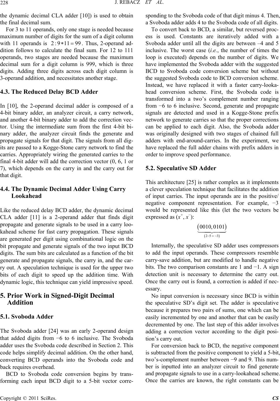 228 J. REBACZ ET AL. the dynamic decimal CLA adder [10]) is used to obtain the final decimal sum. For 3 to 11 operands, only one stage is needed because maximum number of digits for the sum of a digit column with 11 operands is . Thus, 2-operand ad- dition follows to calculate the final sum. For 12 to 111 operands, two stages are needed because the maximum decimal sum for a digit column is 999, which is three digits. Adding three digits across each digit column is 3-operand addition, and necessitates another stage. 2:9 1199 4.3. The Reduced Delay BCD Adder In [10], the 2-operand decimal adder is composed of a 4-bit binary adder, an analyzer circuit, a carry network, and another 4-bit binary adder to add the correction vec- tor. Using the intermediate sum from the first 4-bit bi- nary adder, the analyzer circuit finds the generate and propagate signals for that digit. The signals from all dig- its are passed to a Kogge-Stone carry network to find the carries. Appropriately wiring the generated carries to the final 4-bit adder will add the correction vector (0, 6, 1 or 7), which depends on the carry in and the carry out for that digit. 4.4. The Dynamic Decimal Adder Using Carry Lookahead Like the reduced delay BCD adder, the dynamic decimal CLA adder [11] is a 2-operand adder that finds digit propagate and generate signals to be used in a carry loo- kahead scheme for fast carry propagation. These signals are generated per digit using combinational logic on the bit propagate and generate signals of the two input BCD digits. The sum bits are calculated as a function of the bit generate and propagate signals, the carry in, and the car- ry out. A speculation technique is used for the upper two bits of each digit to speed up the addition time. With dynamic logic, this technique can yield impressive speed. 5. Prior Work in Signed-Digit Decimal Addition 5.1. Svoboda Adder The Svoboda adder [24] was an early 2-operand design that added digits from −6 to 6 inclusive. The Svoboda adder uses the Svoboda code described in Section 2. This code helps simplify decimal addition. On the other hand, converting BCD operands into the Svoboda code and back requires overhead. BCD to Svoboda code conversion begins by trans- forming each input BCD digit to a 5-bit vector corre- sponding to the Svoboda code of that digit minus 4. Then, a Svoboda adder adds 4 to the Svoboda code of all digits. To convert back to BCD, a similar, but reversed proc- ess is used. Constants are iteratively added with a Svoboda adder until all the digits are between –4 and 5 inclusive. The worst case (i.e., the number of times the loop is executed) depends on the number of digits. We have implemented the Svoboda adder with the suggested BCD to Svoboda code conversion scheme but without the suggested Svoboda code to BCD conversion scheme. Instead, we have replaced it with a faster carry-looka- head conversion scheme. First, the Svoboda code is transformed into a two’s complement number ranging from −6 to 6 inclusive. Second, generate and propagate signals are detected and used in a Kogge-Stone prefix network to generate carries so that the proper corrections can be applied to each digit. Also, the Svoboda adder was originally designed with two stages of chained full adders with end-around-carries. In the experiment, we have replaced the full adder chains with prefix adders in order to improve speed performance. 5.2. Speculative SD Adder This architecture [25] is rather complex as it implements a clever speculation technique that facilitates the addition of input carries. The input operands are in the positive/ negative component representation. For example, −3 would be represented like this (let the two vectors be expressed as (x+, x−): 25 3 0010,0101 Internally, the speculative SD adder uses compressors to add the input operands. These compressors resemble carry-save addition, but are modified to handle negative bits. The two comparison constants are 1 and −1. A sign detection unit is necessary to determine the carry out. Once the carry out is found, a correction is added if nec- essary. No input conversion is necessary since BCD is within the speculative SD’s digit set. The adder is speculative because it prepares two pairs of sums, one which can be easily incremented by one and another that can be easily decremented by one. The last step of this adder involves adding a correction vector according to the digit posi- tion’s carry out. For conversion back to BCD, the negative component is subtracted from the positive component to yield a 5-bit, two’s-complement number between −9 and 9. This num- ber is inputted into an analyzer circuit to find generate and propagate signals to use in a carry-lookahead scheme. Once the carries are known, the right constants can be Copyright © 2011 SciRes. CS 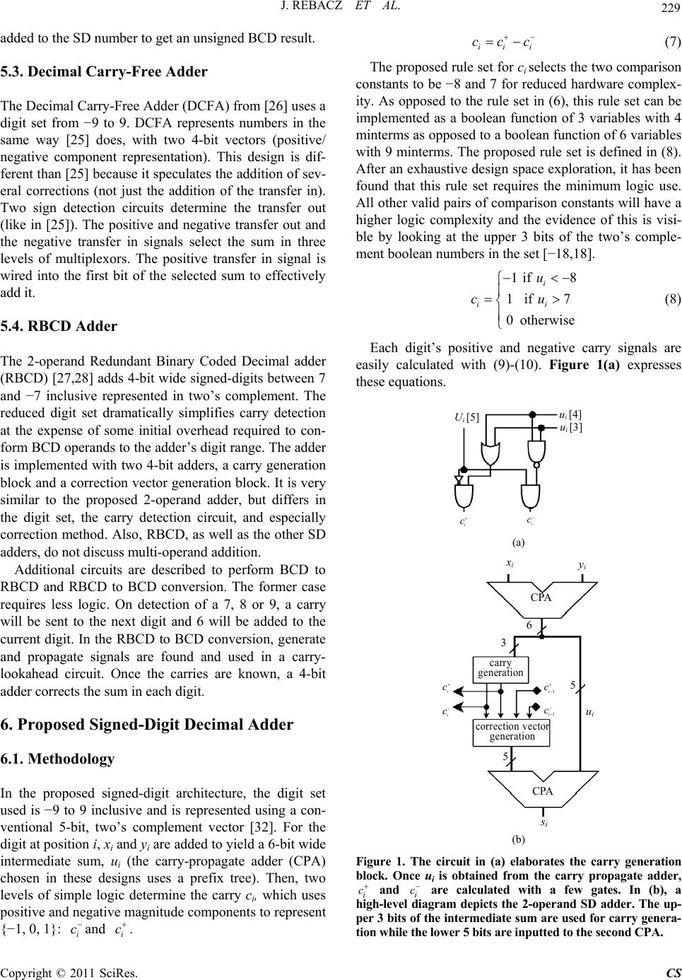 J. REBACZ ET AL. 229 added to the SD number to get an unsigned BCD result. 5.3. Decimal Carry-Free Adder The Decimal Carry-Free Adder (DCFA) from [26] uses a digit set from −9 to 9. DCFA represents numbers in the same way [25] does, with two 4-bit vectors (positive/ negative component representation). This design is dif- ferent than [25] because it speculates the addition of sev- eral corrections (not just the addition of the transfer in). Two sign detection circuits determine the transfer out (like in [25]). The positive and negative transfer out and the negative transfer in signals select the sum in three levels of multiplexors. The positive transfer in signal is wired into the first bit of the selected sum to effectively add it. 5.4. RBCD Adder The 2-operand Redundant Binary Coded Decimal adder (RBCD) [27,28] adds 4-bit wide signed-digits between 7 and −7 inclusive represented in two’s complement. The reduced digit set dramatically simplifies carry detection at the expense of some initial overhead required to con- form BCD operands to the adder’s digit range. The adder is implemented with two 4-bit adders, a carry generation block and a correction vector generation block. It is very similar to the proposed 2-operand adder, but differs in the digit set, the carry detection circuit, and especially correction method. Also, RBCD, as well as the other SD adders, do not discuss multi-operand addition. Additional circuits are described to perform BCD to RBCD and RBCD to BCD conversion. The former case requires less logic. On detection of a 7, 8 or 9, a carry will be sent to the next digit and 6 will be added to the current digit. In the RBCD to BCD conversion, generate and propagate signals are found and used in a carry- lookahead circuit. Once the carries are known, a 4-bit adder corrects the sum in each digit. 6. Proposed Signed-Digit Decimal Adder 6.1. Methodology In the proposed signed-digit architecture, the digit set used is −9 to 9 inclusive and is represented using a con- ventional 5-bit, two’s complement vector [32]. For the digit at position i, xi and yi are added to yield a 6-bit wide intermediate sum, ui (the carry-propagate adder (CPA) chosen in these designs uses a prefix tree). Then, two levels of simple logic determine the carry ci, which uses positive and negative magnitude components to represent {−1, 0, 1}: and . i c i c ii i cc c (7) The proposed rule set for ci selects the two comparison constants to be −8 and 7 for reduced hardware complex- ity. As opposed to the rule set in (6), this rule set can be implemented as a boolean function of 3 variables with 4 minterms as opposed to a boolean function of 6 variables with 9 minterms. The proposed rule set is defined in (8). After an exhaustive design space exploration, it has been found that this rule set requires the minimum logic use. All other valid pairs of comparison constants will have a higher logic complexity and the evidence of this is visi- ble by looking at the upper 3 bits of the two’s comple- ment boolean numbers in the set [−18,18]. 1if8 1if7 0otherwise i ii u cu (8) Each digit’s positive and negative carry signals are easily calculated with (9)-(10). Figure 1(a) expresses these equations. u i [4] i c i c u i [3] U i [5] (a) i y i CPA 3 6 5 i c i c 1i c 1i c CPA u i s i 5 correction vecto generation carry generation (b) Figure 1. The circuit in (a) elaborates the carry generation block. Once ui is obtained from the carry propagate adder, i c and i c are calculated with a few gates. In (b), a high-level diagram depicts the 2-operand SD adder. The up- per 3 bits of the intermediate sum are used for carry genera- tion while the lower 5 bits are inputted to the second CPA. Copyright © 2011 SciRes. CS 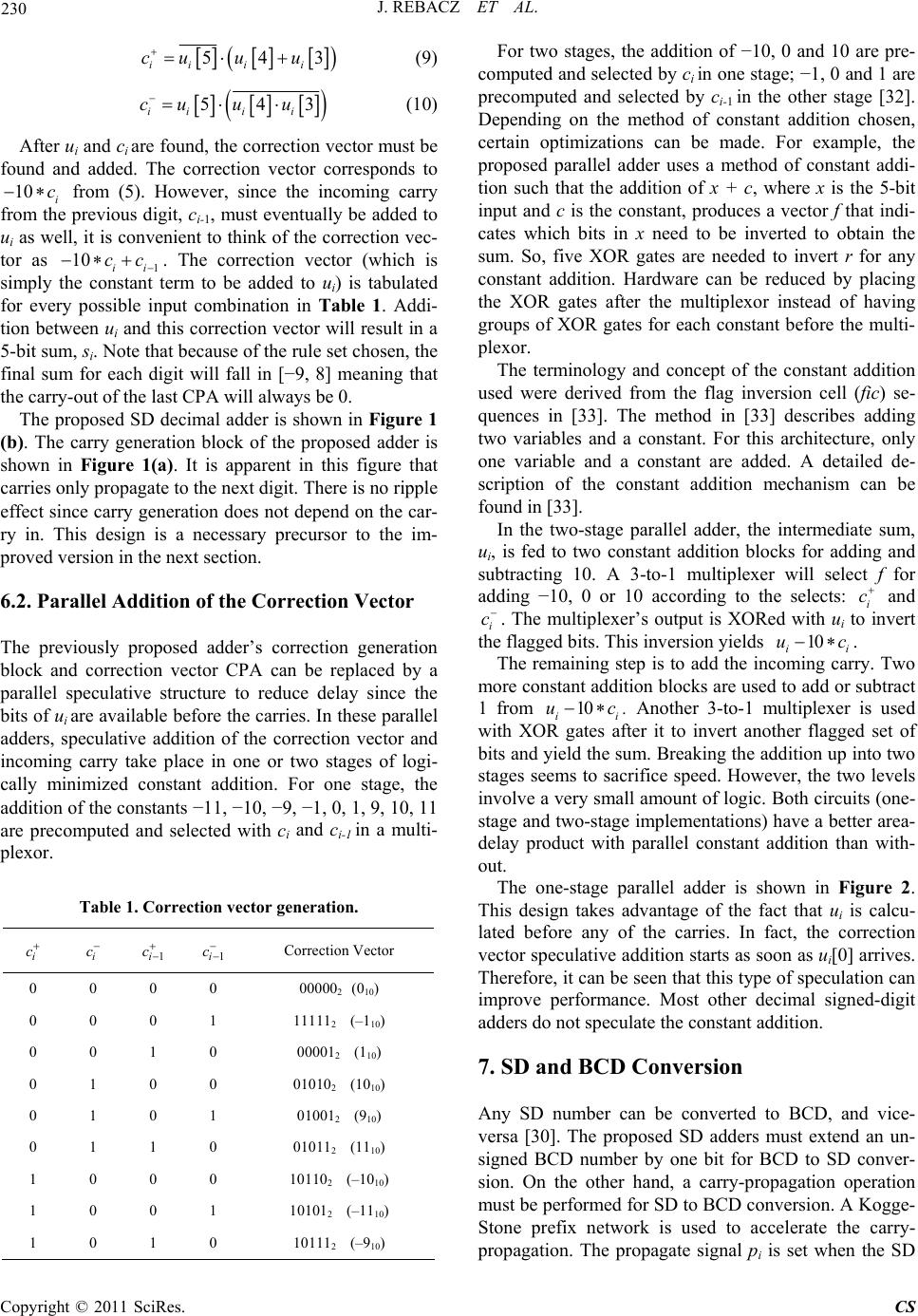 230 J. REBACZ ET AL. 543 ii ii cu uu (9) 543 iii i cuuu (10) After ui and ci are found, the correction vector must be found and added. The correction vector corresponds to from (5). However, since the incoming carry from the previous digit, ci-1, must eventually be added to ui as well, it is convenient to think of the correction vec- tor as 1. The correction vector (which is simply the constant term to be added to ui) is tabulated for every possible input combination in Table 1. Addi- tion between ui and this correction vector will result in a 5-bit sum, si. Note that because of the rule set chosen, the final sum for each digit will fall in [−9, 8] meaning that the carry-out of the last CPA will always be 0. 10 i c 10 ii cc The proposed SD decimal adder is shown in Figure 1 (b). The carry generation block of the proposed adder is shown in Figure 1(a). It is apparent in this figure that carries only propagate to the next digit. There is no ripple effect since carry generation does not depend on the car- ry in. This design is a necessary precursor to the im- proved version in the next section. 6.2. Parallel Addition of the Correction Vector The previously proposed adder’s correction generation block and correction vector CPA can be replaced by a parallel speculative structure to reduce delay since the bits of ui are available before the carries. In these parallel adders, speculative addition of the correction vector and incoming carry take place in one or two stages of logi- cally minimized constant addition. For one stage, the addition of the constants −11, −10, −9, −1, 0, 1, 9, 10, 11 are precomputed and selected with ci and ci-1 in a multi- plexor. Table 1. Correction vector generation. i c i c 1i c 1i c Correction Vector 0 0 0 0 000002 (010) 0 0 0 1 111112 (–110) 0 0 1 0 000012 (110) 0 1 0 0 010102 (1010) 0 1 0 1 010012 (910) 0 1 1 0 010112 (1110) 1 0 0 0 101102 (–1010) 1 0 0 1 101012 (–1110) 1 0 1 0 101112 (–910) For two stages, the addition of −10, 0 and 10 are pre- computed and selected by ci in one stage; −1, 0 and 1 are precomputed and selected by ci-1 in the other stage [32]. Depending on the method of constant addition chosen, certain optimizations can be made. For example, the proposed parallel adder uses a method of constant addi- tion such that the addition of x + c, where x is the 5-bit input and c is the constant, produces a vector f that indi- cates which bits in x need to be inverted to obtain the sum. So, five XOR gates are needed to invert r for any constant addition. Hardware can be reduced by placing the XOR gates after the multiplexor instead of having groups of XOR gates for each constant before the multi- plexor. The terminology and concept of the constant addition used were derived from the flag inversion cell (fic) se- quences in [33]. The method in [33] describes adding two variables and a constant. For this architecture, only one variable and a constant are added. A detailed de- scription of the constant addition mechanism can be found in [33]. In the two-stage parallel adder, the intermediate sum, ui, is fed to two constant addition blocks for adding and subtracting 10. A 3-to-1 multiplexer will select f for adding −10, 0 or 10 according to the selects: i c and i c . The multiplexer’s output is XORed with ui to invert the flagged bits. This inversion yields . 10 ii uc The remaining step is to add the incoming carry. Two more constant addition blocks are used to add or subtract 1 from i u10 i c . Another 3-to-1 multiplexer is used with XOR gates after it to invert another flagged set of bits and yield the sum. Breaking the addition up into two stages seems to sacrifice speed. However, the two levels involve a very small amount of logic. Both circuits (one- stage and two-stage implementations) have a better area- delay product with parallel constant addition than with- out. The one-stage parallel adder is shown in Figure 2. This design takes advantage of the fact that ui is calcu- lated before any of the carries. In fact, the correction vector speculative addition starts as soon as ui[0] arrives. Therefore, it can be seen that this type of speculation can improve performance. Most other decimal signed-digit adders do not speculate the constant addition. 7. SD and BCD Conversion Any SD number can be converted to BCD, and vice- versa [30]. The proposed SD adders must extend an un- signed BCD number by one bit for BCD to SD conver- sion. On the other hand, a carry-propagation operation must be performed for SD to BCD conversion. A Kogge- Stone prefix network is used to accelerate the carry- propagation. The propagate signal pi is set when the SD Copyright © 2011 SciRes. CS 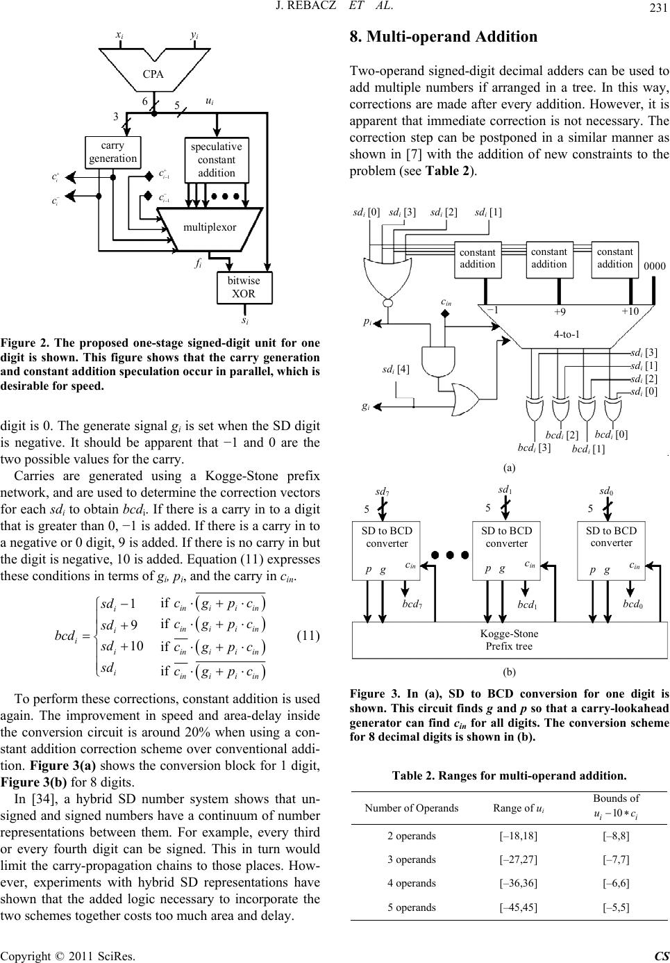 J. REBACZ ET AL. 231 carry generation i y i CP u i f i s i speculative constant addition multi ple xo bitwise XOR 3 6 5 i c i c 1i c 1i c Figure 2. The proposed one-stage signed-digit unit for one digit is shown. This figure shows that the carry generation and constant addition speculation occur in paralle l, which is desirable for speed. digit is 0. The generate signal gi is set when the SD digit is negative. It should be apparent that −1 and 0 are the two possible values for the carry. Carries are generated using a Kogge-Stone prefix network, and are used to determine the correction vectors for each sdi to obtain bcdi. If there is a carry in to a digit that is greater than 0, −1 is added. If there is a carry in to a negative or 0 digit, 9 is added. If there is no carry in but the digit is negative, 10 is added. Equation (11) expresses these conditions in terms of gi, pi, and the carry in cin. if 1 if 9 10 if if inii in i inii in i i iinii in iinii in cgpc sd cgpc sd bcd sd cgpc sd cgpc (11) To perform these corrections, constant addition is used again. The improvement in speed and area-delay inside the conversion circuit is around 20% when using a con- stant addition correction scheme over conventional addi- tion. Figure 3(a) shows the conversion block for 1 digit, Figure 3(b) for 8 digits. In [34], a hybrid SD number system shows that un- signed and signed numbers have a continuum of number representations between them. For example, every third or every fourth digit can be signed. This in turn would limit the carry-propagation chains to those places. How- ever, experiments with hybrid SD representations have shown that the added logic necessary to incorporate the two schemes together costs too much area and delay. 8. Multi-operand Addition Two-operand signed-digit decimal adders can be used to add multiple numbers if arranged in a tree. In this way, corrections are made after every addition. However, it is apparent that immediate correction is not necessary. The correction step can be postponed in a similar manner as shown in [7] with the addition of new constraints to the problem (see Table 2). sd i [0] constant addi t i on sd i [3]sd i [2]sd i [1] sd i [4] constant addition co n stant addition 0000 sd i [1] sd i [3] sd i [2] sd i [0] +10 +9 −1 4-to-1 bcd i [1] bcd i [2] bcd i [3] bcd i [0] p i c in g i (a) sd 7 sd 1 sd 0 555 SD to BCD converter pgc in bcd 7 pg c in bcd 1 SD to BCD converter SD to BCD converter p gc in bcd 0 Kogge-Stone Prefix tree (b) Figure 3. In (a), SD to BCD conversion for one digit is shown. This circuit finds g and p so that a carry-lookahead generator can find cin for all digits. The conversion scheme for 8 decimal digits is shown in (b). Table 2. Ranges for multi-operand addition. Number of Operands Range of ui Bounds of 10 ii uc 2 operands [–18,18] [–8,8] 3 operands [–27,27] [–7,7] 4 operands [–36,36] [–6,6] 5 operands [–45,45] [–5,5] Copyright © 2011 SciRes. CS 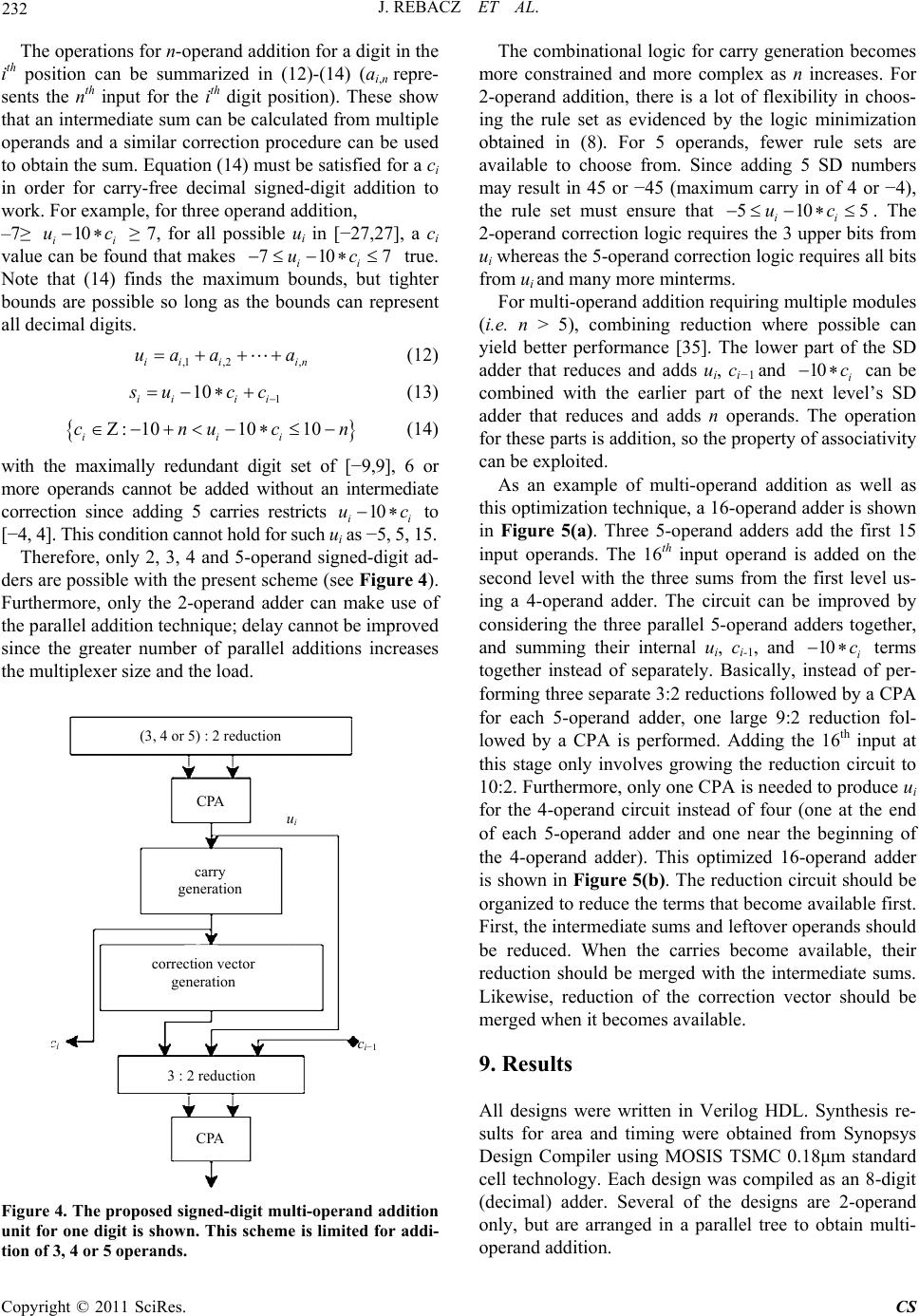 J. REBACZ ET AL. 232 c 7 n The operations for n-operand addition for a digit in the ith position can be summarized in (12)-(14) (ai,n repre- sents the nth input for the ith digit position). These show that an intermediate sum can be calculated from multiple operands and a similar correction procedure can be used to obtain the sum. Equation (14) must be satisfied for a ci in order for carry-free decimal signed-digit addition to work. For example, for three operand addition, –7≥ i ≥ 7, for all possible ui in [−27,27], a ci value can be found that makes true. Note that (14) finds the maximum bounds, but tighter bounds are possible so long as the bounds can represent all decimal digits. 10 i u 710 ii uc ,1 ,2,ii ii ua aa (12) 1 10 ii ii ucc (13) :1010 10 iii cnuc n (14) with the maximally redundant digit set of [−9,9], 6 or more operands cannot be added without an intermediate correction since adding 5 carries restricts to [−4, 4]. This condition cannot hold for such ui as −5, 5, 15. 10 ii uc Therefore, only 2, 3, 4 and 5-operand signed-digit ad- ders are possible with the present scheme (see Figure 4). Furthermore, only the 2-operand adder can make use of the parallel addition technique; delay cannot be improved since the greater number of parallel additions increases the multiplexer size and the load. CPA correction vector generation i c i−1 3 : 2 reduction carry generation u i CPA (3, 4 or 5) : 2 reduction Figure 4. The proposed signed-digit multi-operand addition unit for one digit is shown. This scheme is limited for addi- tion of 3, 4 or 5 operands. The combinational logic for carry generation becomes more constrained and more complex as n increases. For 2-operand addition, there is a lot of flexibility in choos- ing the rule set as evidenced by the logic minimization obtained in (8). For 5 operands, fewer rule sets are available to choose from. Since adding 5 SD numbers may result in 45 or −45 (maximum carry in of 4 or −4), the rule set must ensure that . The 2-operand correction logic requires the 3 upper bits from ui whereas the 5-operand correction logic requires all bits from ui and many more minterms. 510 ii uc5 For multi-operand addition requiring multiple modules (i.e. n > 5), combining reduction where possible can yield better performance [35]. The lower part of the SD adder that reduces and adds ui, ci−1 and can be combined with the earlier part of the next level’s SD adder that reduces and adds n operands. The operation for these parts is addition, so the property of associativity can be exploited. 10 i c As an example of multi-operand addition as well as this optimization technique, a 16-operand adder is shown in Figure 5(a). Three 5-operand adders add the first 15 input operands. The 16th input operand is added on the second level with the three sums from the first level us- ing a 4-operand adder. The circuit can be improved by considering the three parallel 5-operand adders together, and summing their internal ui, c i-1, and terms together instead of separately. Basically, instead of per- forming three separate 3:2 reductions followed by a CPA for each 5-operand adder, one large 9:2 reduction fol- lowed by a CPA is performed. Adding the 16th input at this stage only involves growing the reduction circuit to 10:2. Furthermore, only one CPA is needed to produce ui for the 4-operand circuit instead of four (one at the end of each 5-operand adder and one near the beginning of the 4-operand adder). This optimized 16-operand adder is shown in Figure 5(b). The reduction circuit should be organized to reduce the terms that become available first. First, the intermediate sums and leftover operands should be reduced. When the carries become available, their reduction should be merged with the intermediate sums. Likewise, reduction of the correction vector should be merged when it becomes available. 10 i c 9. Results All designs were written in Verilog HDL. Synthesis re- sults for area and timing were obtained from Synopsys Design Compiler using MOSIS TSMC 0.18μm standard cell technology. Each design was compiled as an 8-digit (decimal) adder. Several of the designs are 2-operand only, but are arranged in a parallel tree to obtain multi- operand addition. Copyright © 2011 SciRes. CS 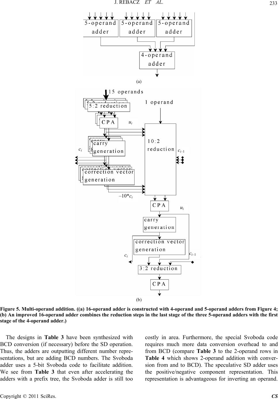 J. REBACZ ET AL. Copyright © 2011 SciRes. CS 233 (a) ui ci ci–1 10*ci ui ci–1 ci (b) Figure 5. Multi-operand addition. ((a) 16-operand adder is constructed with 4-operand and 5-operand adders from Figure 4; (b) An improved 16-operand adder combines the reduction steps in the last stage of the three 5-operand adders with the first stage of the 4-operand adder.) The designs in Table 3 have been synthesized with BCD conversion (if necessary) before the SD operation. Thus, the adders are outputting different number repre- sentations, but are adding BCD numbers. The Svoboda adder uses a 5-bit Svoboda code to facilitate addition. We see from Table 3 that even after accelerating the adders with a prefix tree, the Svoboda adder is still too costly in area. Furthermore, the special Svoboda code requires much more data conversion overhead to and from BCD (compare Table 3 to the 2-operand rows in Table 4 which shows 2-operand addition with conver- sion from and to BCD). The speculative SD adder uses the positive/negative component representation. This representation is advantageous for inverting an operand.  234 J. REBACZ ET AL. Additionally, there is no overheard required for convert- ing to the adder’s representation. However, the area and delay requirements are too much compared to other de- signs. The DCFA [26] achieves a better area-delay product than the speculative SD while using the same number representation. The RBCD adder is strong in terms of delay and area, but the conversion from BCD puts RBCD behind many of the adders. The results in Table 3 for our proposed adders dem- onstrate two points: i) The adder architecture is efficient in terms of area and delay and ii) The constant addition modification can improve delay or area (see last two rows). The architecture referred to by Table 3 as the proposed SD is shown in Figure 1. The proposed one-stage SD is shown in Figure 2. The advantage of the proposed SD's number representation is that it requires no conversion from BCD. Additionally, a digit's sign information is found in the digit's most significant bit. For the representation used in the speculative adder and the DCFA, a sign detector must be used on each digit to determine the digit’s sign. Therefore, we believe the proposed designs offer superior performance with the two’s complement representation. For the multi-operand results, every adder inputs de- cimal digits in the BCD representation and outputs an unsigned BCD sum vector. An additional conversion step is necessary after all SD adders and before the RBCD and Svoboda adders. Since the operand size is 8 digits, the carry-free advantage of the SD adders is not being leveraged. Table 3. Area and delay comparison for 2-operand SD ad- ders. Decimal Adder Delay (ns) Area (mm2) Area-Delay (ns*mm2) Area-Delay compared to Proposed SD RBCD [27,28] 1.66 0.03840.0637 × 1.26 Svoboda SD [24] 2.18 0.08980.1960 × 3.87 Speculative SD [25] 1.40 0.05820.0815 × 1.61 DCFA [26] 1.48 0.04980.0737 × 1.45 Proposed SD 1.36 0.03730.0507 × 1.00 Proposed 1-stage SD 1.27 0.03850.0489 × 0.96 Proposed 2-stage SD 1.36 0.03460.0471 × 0.93 Table 4 shows that the multi-operand SD adder pro- posed in this work outperforms the existing SD designs at every corner (except against the RBCD adder’s area for two operands). The RBCD adder occupies the least area for 2 and 4 operands, but falls second to the pro- posed adder for 8 and 16 operands. For hardware designs that can benefit from the two’s complement SD repre- sentation, the proposed architecture should be considered. Among the unsigned adders in Table 5, the dynamic decimal adder using CLA yields the best delay. It also consumes the least area for 2 and 4 operands. For 8 and 16 operands, the mixed binary and BCD adder architec- ture yields the best area-delay product. It may be specu- lated that the mixed binary and BCD approach will scale best, since the main growing component is the fast tree of binary adders. Table 4. Area and delay comparison for signed multi-ope- rand adders. Operands Delay (ns) Area (mm2) Area-Delay (ns*mm2) Area-Delay compared to Proposed SD Svoboda Adder [24] 2 3.39 0.110 0.373 × 3.42 4 4.93 0.242 1.19 × 5.36 8 6.50 0.477 3.10 × 4.58 16 8.15 0.912 7.43 × 4.17 Speculative SD Adder [25] 2 2.51 0.0713 0.179 × 1.64 4 3.89 0.129 0.502 × 2.26 8 5.22 0.288 1.50 × 2.22 16 6.83 0.545 3.72 × 2.09 DCFA Adder [26] 2 2.79 0.0675 0.188 × 1.72 4 4.15 0.172 0.714 × 3.22 8 5.90 0.323 1.91 × 2.82 16 7.40 0.649 4.80 × 2.70 RBCD Adder [27,28] 2 2.67 0.0486 0.130 × 1.19 4 3.73 0.0794 0.295 × 1.33 8 5.01 0.154 0.772 × 1.14 16 6.21 0.306 1.90 × 1.07 Proposed SD Adder 2 2.08 0.0539 0.109 × 1.00 4 3.18 0.0698 0.222 × 1.00 8 4.37 0.155 0.677 × 1.00 16 5.49 0.324 1.78 × 1.00 Copyright © 2011 SciRes. CS  J. REBACZ ET AL. 235 Table 5. Area and Delay Comparison for unsigned multi- operand adders. Operands Delay (ns) Area (mm2) Area-Delay (ns*mm2) Nonspeculative Adder [7] 2 1.29 .0246 .0317 4 3.15 .0614 .193 8 4.03 .147 .592 16 6.78 .280 1.90 Mixed Binary and BCD Adder [23] 2 1.29 .0246 .0317 4 2.71 .0535 .145 8 3.41 .101 .344 16 4.45 .187 .832 Reduced Delay BCD Adder [10] 2 1.34 .0284 .0381 4 2.57 .0644 .166 8 3.68 .143 .526 16 4.84 .278 1.34 Dynamic Decimal using CLA Adder [11] 2 1.29 .0246 .0317 4 2.38 .0598 .142 8 3.01 .123 .370 16 3.82 .236 .902 Proposed SD multi-operand addition with conversion to BCD does not outperform the best unsigned multi- operand scheme. However, the SD adders’ larger func- tional domain must not be overlooked. That is, the ease at which subtraction can be performed with an SD adder over an unsigned adder strengthens the SD adder’s posi- tion. 10. Applications The ideal target applications for the proposed signed- digit schemes would leverage signed-digit advantages. One benefit is the elimination of carry propagation addi- tion with long words (64 or 128 bits) operated on itera- tively. If the application does not require iterative com- putations, then immediate conversion back to an un- signed representation will negate the carry-free addition performance. However, if the application requires know- ledge of sign at each iterative step, which signed-digit addition easily provides, then signed-digit addition is promising. Moreover, applications that can conveniently use the signed-digit representation for other operations as well as addition/subtraction stand to benefit. The itera- tive multiplier in [15] uses a signed-digit adder because an earlier step (partial product generation) found that the signed-digit representation can increase performance. In SRT division, division is executed iteratively and the sign of the dividend is necessary at each iteration. Therefore, the proposed 2-operand adders can potentially serve a core role in division. For the proposed multi-operand scheme, adding multiple partial products to reduce cycles in iterative multiplication appears promising. Finally, advanced financial algorithms may stand to benefit. 11. Conclusions In this study, new signed-digit two operand and multi- operand decimal adders are proposed. Performance of re- cent decimal adder architectures have been investigated and compared. The proposed SD adder excels in speed and area usage among previously proposed SD adders. The use of constant addition for speculation and the merg- ing of adjacent modules with sharable operations enable efficient implementation of two operand and multi-op- erand decimal addition. 12. References [1] BigDecimal, 2008. http://java.sun.com/products. [2] DecNumber, AlphaWorks, 2008. http://www.alphaworks.ibm.com/tech/decnumber. [3] L. Eisen, et al., “IBM POWER6 Accelerators: VMX and DFU,” IBM Journal of Research and Development, Vol. 51, No. 6, 2007, pp. 663-683. doi:10.1147/rd.516.0663 [4] C. Webb, “IBM z10: The Next-Generation Mainframe Microprocessor,” IEEE Micro, Vol. 28, No. 2, 2008, pp. 19-29. doi:10.1109/MM.2008.26 [5] A. Tsang and M. Olschanowsky, “A Study of Database 2 Customer Queries,” Technical Report TR-03.413, IBM Santa Teresa Laboratory, San Jose, USA, 1991. [6] L.-K. Wang, C. Tsen, M. Schulte and D. Jhalani, “Benchmarks and Performance Analysis of Decimal Floating-Point Applications,” 5th International Confer- ence on Computer Design, Lake Tahoe, 7-10 October 2007, pp. 164-170. doi:10.1109/ICCD.2007.4601896 [7] R. Kenney and M. Schulte, “High-Speed Multioperand Decimal Adders,” IEEE Transactions on Computers, Vol. 54, No. 8, 2005, pp. 953-963. doi:10.1109/TC.2005.129 [8] I. D. Castellanos and J. E. Stine, “Compressor Trees for Decimal Partial Product Reduction,” GLSVLSI’08: Pro- ceedings of the 18th ACM Great Lakes Symposium on VLSI, ACM, Orlando, 4-6 May 2008, pp. 107-110. [9] I. S. Hwang, “High Speed Binary and Decimal Arithme- tic Unit,” USA Patent No. 4,866,656. [10] A. Bayrakci and A. Akkas, “Reduced Delay BCD Ad- der,” IEEE International Conference on Application Spe- cific Systems, Architectures and Processors, Montreal, 9-11 July 2007, pp. 266-271. [11] Y. You, Y. D. Kim and J. H. Choi, “Dynamic Decimal Adder Circuit Design by Using the Carry Lookahead,” Copyright © 2011 SciRes. CS  J. REBACZ ET AL. Copyright © 2011 SciRes. CS 236 IEEE Design and Diagnostics of Electronic Circuits and Systems, Prague, 18-21 April 2006, pp. 242-244. doi:10.1109/DDECS.2006.1649627 [12] L.-K. Wang and M. Schulte, “A Decimal Floating-Point Adder with Decoded Operands and a Decimal Lead- ing-Zero Anticipator,” 19th IEEE Symposium on Com- puter Arithmetic, Portland, 8-10 June 2009, pp. 125-134. [13] A. Vazquez and E. Antelo, “A High-Performance Sig- nificand BCD Adder with IEEE 754-2008 Decimal Rounding,” 19th IEEE Symposium on Computer Arith- metic, Portland, 8-10 June 2009, pp. 135-144. [14] L.-K. Wang and M. Schulte, “Decimal Floating-Point Adder and Multifunction Unit with Injection-Based Rounding,” 18th IEEE Symposium on Computer Arith- metic, Montpellier, 25-27 June 2007, pp. 56-68. [15] M. Erle, E. Schwarz and M. Schulte, “Decimal Multipli- cation with Efficient Partial Product Generation,” 17th IEEE Symposium on Computer Arithmetic, Cape Cod, 27-29 June 2005, pp. 21-28. [16] M. Erle, M. Schulte and B. Hickmann, “Decimal Float- ing-Point Multiplication via Carry-Save Addition,” 18th IEEE Symposium on Computer Arithmetic, Montpellier, 25-27 June 2007, pp. 46-55. [17] A. Vazquez, E. Antelo and P. Montuschi, “A New Family of High-Performance Parallel Decimal Multipliers,” 18th IEEE Symposium on Computer Arithmetic, Montpellier, 25-27 June 2007, pp. 195-204. [18] G. Jaberipur and A. Kaivani, “Improving the Speed of Parallel Decimal Multipliers,” IEEE Transactions on Computers, Vol. 58, No. 11, 2009, pp. 1539-1552. doi:10.1109/TC.2009.110 [19] T. Lang and A. Nannarelli, “A Radix-10 Digit-Recurrence Division Unit: Algorithm and Architecture,” IEEE Trans- actions on Computers, Vol. 56, No. 6, 2007, pp. 727-739. doi:10.1109/TC.2007.1038 [20] A. Vazquez, E. Antelo and P. Montuschi, “A Radix-10 SRT Divider Based on Alternative BCD Codings,” 25th International Conference on Computer Design, Lake Tahoe, 7-10 October 2007, pp. 280-287. [21] H. Nikmehr, B. Phillips and C. Lim, “Fast Decimal Floating-Point Division,” IEEE Transactions on Very Large Scale Integration (VLSI) Systems, Vol. 14, No. 9, 2006, pp. 951-961. [22] A. Kaivani and G. Jaberipur, “Fully Redundant Decimal Addition and Subtraction Using Stored-Unibit Encod- ing,” Integration, the VLSI journal, Vol. 43, No. 1, 2010, pp. 34-41. [23] L. Dadda, “Multioperand Parallel Decimal Adder: A Mixed Binary and BCD Approach,” IEEE Transactions on Computers, Vol. 56, No. 10, 2007, pp. 1320-1328. doi:10.1109/TC.2007.1067 [24] A. Svoboda, “Decimal Adder with Signed Digit Arithme- tic,” IEEE Transactions on Computers, Vol. C-18, No. 3, 1969, pp. 212-215. doi:10.1109/T-C.1969.222633 [25] J. Moskal, E. Oruklu and J. Saniie, “Design and Synthesis of a Carry-Free Signed-Digit Decimal Adder,” IEEE In- ternational Symposium on Circuits and Systems, New Orleans, 27-30 May 2007, pp. 1089-1092. [26] H. Nikmehr, B. Phillips and C. Lim, “A Decimal Car- ry-Free Adder,” Smart Structures, Devices, and Sys- tems-II, Sydney, 13 December 2005, pp. 786-797. [27] B. Shirazi, D. Yun and C. Zhang, “RBCD: Redundant Binary Coded Decimal Adder,” IEE Proceedings on Computers and Digital Techniques, Vol. 136, No. 2, 1989, pp. 156-160. doi:10.1049/ip-e.1989.0021 [28] B. Shirazi, D. Yun and C. Zhang, “VLSI Designs for redundant Binary-Coded Decimal Addition,” 7th Annual International Phoenix Conference on Computers and Communications, Scottsdale, 16-18 March 1988, pp. 52-56. doi:10.1109/PCCC.1988.10042 [29] R. Kenney, M. Schulte and M. Erle, “A High-Frequency Decimal Multiplier,” IEEE International Conference on Computer Design: VLSI in Computers and Processors, San Jose, 11-13 October 2004, pp. 26-29. doi:10.1109/ICCD.2004.1347893 [30] A. Avizienis, “Signed Digit Number Representations for Fast Parallel Arithmetic,” IRE Transactions on Electronic Computers, Vol. EC-10, No. 3, 1961, pp. 389-400. doi:10.1109/TEC.1961.5219227 [31] B. Parhami, “Generalized Signed-Digit Number Systems: A Unifying Framework for Redundant Number Repre- sentations,” IEEE Transactions on Computers, Vol. 39, No. 1, 1990, pp. 89-98. doi:10.1109/12.46283 [32] J. Rebacz, E. Oruklu and J. Saniie, “High Performance Signed-Digit Decimal Adders,” IEEE International Con- ference on Electro/Information Technology, Windsor, 7-9 June 2009, pp. 251-255. doi:10.1109/EIT.2009.5189621 [33] V. Dave, E. Oruklu and J. Saniie, “Design and Synthesis of a Three Input Flagged Prefix Adder,” IEEE Interna- tional Symposium on Circuits and Systems, New Orleans, 27-30 May 2007, pp. 1081-1084. doi:10.1109/ISCAS.2007.378197 [34] D. Phatak and I. Koren, “Hybrid Signed-Digit Number Systems: A United Framework for Redundant Number Representations with Bounded Carry Propagation Chains,” IEEE Transactions on Computers, Vol. 43, No. 8, 1994, pp. 880-891. doi:10.1109/12.295850 [35] J. Rebacz, E. Oruklu and J. Saniie, “Performance Evalua- tion of Multi-Operand Fast Decimal Adders,” 52nd IEEE International Midwest Symposium on Circuits and Sys- tems, Cancun, 2-5 August 2009, pp. 535-538. doi:10.1109/MWSCAS.2009.5236036
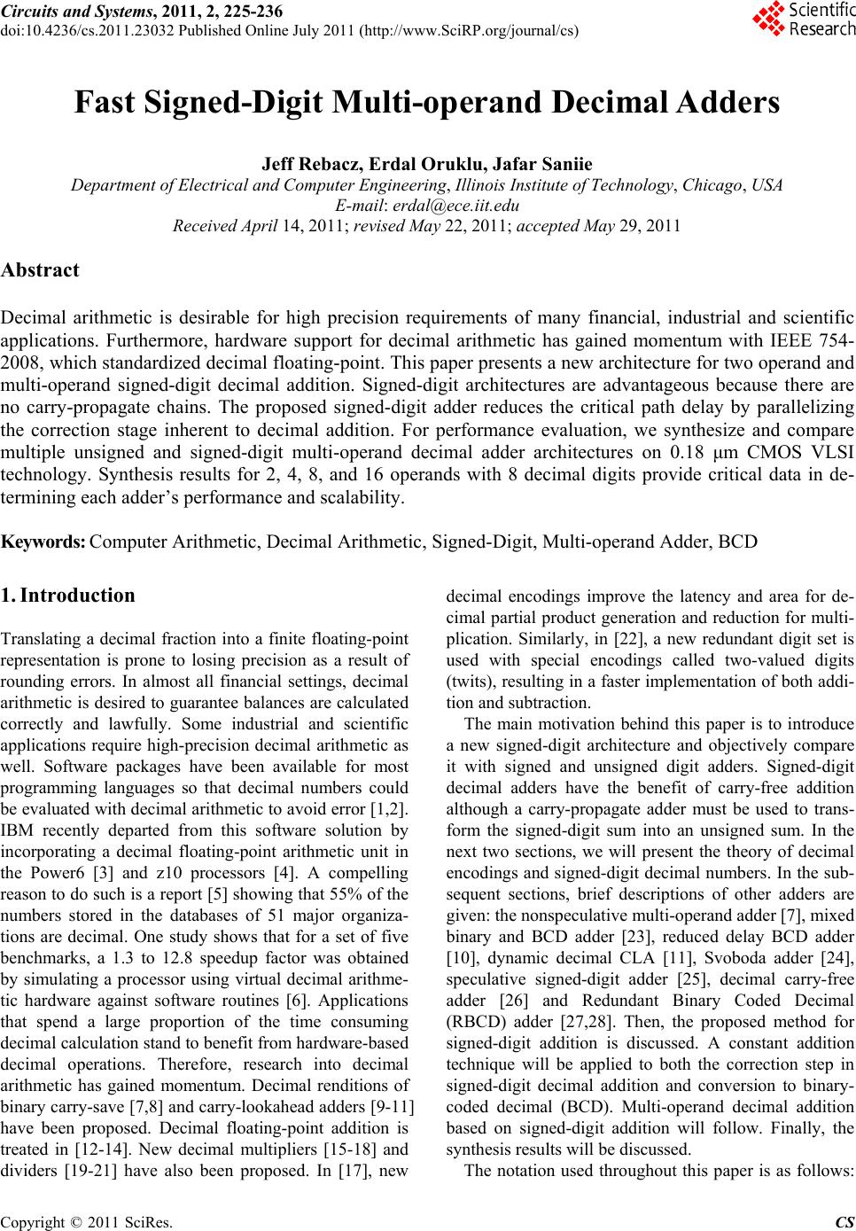
|