 Energy and Power Engineering, 2015, 7, 546-555 Published Online Oc to ber 2015 in SciRes. htt p: // w ww.sc ir p. o rg/ j o ur nal /epe http://dx.doi.org/10.4236/epe.2015.711051 How to cite this paper: Asghar, S.B. and Singh, R.K. (2015) Simulink Based Analysis and Realization of Solar PV System. Energy and Power Engineering, 7, 546-555. http://dx.doi.org/10.4236/epe.2015.711051 Simulink Based Analysis and Realization of Solar PV System S. Badie Asghar, R. K. Singh 1Department of Electrical and Electronics Engineering, MACET, Bihar, India 2Department of Electrical Engineering, MIT, Bihar, India Email: s.b.asghar2010@gmail.com, rafiq.abuturab@gmail.com Received 28 June 2015; accepted 27 October 2015; published 30 October 2015 Copyright © 2015 by authors and Scientific Research Publishing Inc. This work is licensed under the Creative Commons Attribution International License (CC BY). http://creativecommons.org/licenses/by/4.0/ Abstract Non-conventional energy resources are increasingly used to fulfill load demands. Before using such energy sources, the very important thing is analysis at the basic level. This paper presents analysis and realization of solar PV system. The current-voltage and power-voltage characteristics of solar PV array changes as parameters like solar insolation, and temperature changes. These characteristics are found and realized by using MATLAB software. Keywords Effect of Ambient Conditions, Modeling of PV Cell, Series Parallel Connection of PV Cells, Solar PV System 1. Introduction One of the major concerns in the power sector is the day-to-day increas ing po wer demand b ut the unavailab ility of enough resources to meet the power demand using the conventional energy sources. Demand has increased for r enewabl e sourc es of e nergy to be utili zed al ong wit h conve ntional syste ms to meet the energy demand. Re- newable sources like wind energy and solar energy are the major energy sources which are being utilized in this regard. The continuous use of fossil fuels has caused the fossil fuel deposit to be reduced and has affected the environment emptying the biosphere and gradually adding to global warming. Solar energy is widely available that has made it possible to yield it and utilize it properly. Solar energy can be a standalone generating unit or can be a grid connected generating unit d ependi ng on the a vailab ility of grid closeness. Thus it can be used to power rural areas where the availability of grids is very low. Another advan- tage of using solar energy is the portable operation whenever necessary.  S. B. Asghar, R. K. Singh 2. Solar PV System Photovolta ic cells convert radiant energy from the sun directly into electricity. Photovoltaic cell provides a clean, reliable energy without consuming fossil, and is free from hazardous product. Sun is the mother of all energies (except nuclear and geothermal) that provides almost all the energy needed to support life, and can be used in variety of applications. On average, the earth receives about 1.2 × 10¹⁷ W of solar power. The challenge for a sustainable futur e is to tap a tiny fraction of this ener gy to supp ly the relatively modest demands of human activ- ities. The increasing use of these solar cells is linked to economic, efficiency and reliability factors and recent advances in solid sta te tech nologies has gi ven a boo st to the attractive ness of solar ce lls with hig h ef ficie nc y so- lar cells now available. A Schematic block diagram of a PV cell is shown in Figure 1. 1) I-V Characteristics of solar cell Solar cell generator is neither a constant voltage nor a constant current source. The current is proportional to solar insolation and voltage is a functio n of the current required b y the load [1]. A typical I-V characteristic of the solar cell for a certain ambient irradiation S and a certain fixed cell temper- ature T is shown in Figure 2. For a resistive load , the load characteristic is a stra ight line with slope I/V = 1/R. It should be pointed out that the power delivered to the load depends on the value of the resistance only. Figure 1. Schematic d iagram of P V cell. Figure 2. I-V charact eristics of solar cell.  S. B. Asghar, R. K. Singh 2) Effect of Ambient Conditio ns on I-V Characte ristics of PV Cell The I-V characteristics of a PV cell is weather dependent, the effect of change in ambient temperature and solar insolation on the I -V characteristics is shown in Figure 3 and Figure 4 that the open circuit voltage de- creases linearly with the increase in the cell te mperature and open circuit voltage increases logarith mically with the ambient irradiation, while the short c ircuit current is a linear functio n of the ambient irradia tion. 3) Effect of Ser ies and Paralle l Co nnection on I -V Characteristics of PV Cell 4) PV Generator Hierarchy 3. Modeling of Photovoltaic Cell Photovoltaic (PV) system directly converts sunlight into electricity. The basic device of a PV system is the PV cell. Cells may be grouped to form panels or arrays. The voltage ¤t available at the terminals of a PV de- vice may directly feed small loads such as lighting systems and DC motors. M ore sophisticated app lications re- quire electronic converters to process the electricity from the PV device .These converters may be used to regu- late the volta ge and c urr ent at the lo ad, to co ntrol the power flow i n gri d -connected systems, and mainly to track the maximum power po int (MP P) of the device [2]. A PV device may be any element that converts sunlight into electr icity. The elementary P V device is the PV cell. A set of connected cells form a panel. Panels are generally composed of series cells in order to obtain large output voltages. Panels with large output currents are achieved by increasing the surface area of the cells or by connecting cells in parallel. A PV array may be either a pan el or a set of panels connected in series or parallel to form large PV systems. This paper focuses on PV arra ys and sho ws how to obtain the parameters of the I-V eq- uation from practical data obtained in datasheets [3]. Series & parallel connection & PV hierarchy is shown in Figure 5 & Figure 6 respectively. Figure 3. Effect of temperature on I-V characteristics. Figure 4. Effect of Solar irradiation on I-V characteristics.  S. B. Asghar, R. K. Singh Figure 5. Series & P arallel con nection on I-V characteri stics. Figure 6. PV generator hierarchy. 3.1. Simplest Model (Ideal Case) The simple st model o f a PV c ell and i ts eq uiva lent cir cui t is pr esent ed i n F igur e t hat co nsi sts o f a n id eal c urr ent source in paralle l with an idea l diode with zero ser ies resistance, in finite shunt resi stance and u nity ideality fac- tor for juncti on. The output current (IC) from the PV cell is found by applying the Kirchoff’s current law on the equivalent circuit in Figure 7. (1) where Isc is a short circuit current. T he diode current Id is given by Shockley di ode equa tion. (2) Vd is the voltage across the diode (D). For the ideal case, this voltage is equal to the cell voltage, Vc; k is Boltzmann constant (1.38 × 10⁻²³ J/K); q is electron charge (1.602 × 10⁻¹⁹ C); I0 is reverse saturation current of diode (0.000025 A); Tc is reference cell operating temperature (25˚C). Using above equations, the current and voltage of the PV cell can be written as:  S. B. Asghar, R. K. Singh Figure 7. Equivalent Cir cui t of PV cell ( Id eal case). 0 1 e c c qV k cT Ph II I − = − (3) 0 0 ln c Phc c kTII I VqI +− = (4) The reverse saturation current of diode (I0) is constant under the constant t empera ture and found by settin g the open-circuit condition, the open circuit voltage is obtained as: 0 0 ln c Ph oc kTI I qI V + = (5) As above equation can be written as: (6) To a ver y good approximatio n, the photon ge nerated current, which is equal to Isc, is directly proportional to the irradiance, the intensit y of illumi nation, to PV c ell. Thus, if the val ue , Isc, is known fro m the d at as he et , u nd er the standard te st conditio n, Sc = 1000 W/m2 at the air mass (AM) = 1 .5, then the photon generate d current at any other irradiance, Sx in (W/m2), is given by: (7) 3.2. More Accurate Model (Non-Ideal Case) Some researchers on photovoltaic models use constant parameters (i.e. ideality factor A, series resistance Rs, and shunt r esist a nce Rp,) , which result in modeling inaccuracy. In reality, these parameters vary with the temperature change. For better results consideration of these effects is necessary. Figure 8 sho ws a more accurate equivalent circuit of a PV cell [4]. 3.2.1. Series Resistance In a practical PV cell, there is a series of resistance in a current path through the semiconductor material, the metal grid, contacts, and current collecting bus. These resistive losses are lumped together as a series resister (Rs). Its effect becomes very conspicuous in a PV module that consists of many series-connected cells, and the value of resista nce is multiplied by the number of cells. 3.2.2. Parallel Resistance This is also called shunt resistance. It is a loss associated with a small leakage of current through a resistive path in parallel with the intrinsic device. This can be represented by a parallel resister (Rp). Its effect is much less conspicuous in a PV module compared to the series resistance, and it will only become noticeable when a number  S. B. Asghar, R. K. Singh Figure 8. Equivalent circuit of PV cell (non ideal case). of PV modules are connected in parallel for a larger system [5]. 0 e1 c cs c V IR qAkT cP cs p hc II IV IR R + = − + −− (8) where A is known as the “ideality factor of junction” ( “A” is sometimes denoted as “n”). After rearranging the above equation we can write I-V equation a s shown belo w: 0 00 ln cPhccc s c cs P AkTIIIVI R V IR q IIR +− + = −− (9) 4. Modeling of Solar PV System Using Matlab Simulink The MATLAB/SIMULINK software has been used for the modeling and simulation purposes [3] [6]. Model and circuit design for PV array are shown in Figure 9 and Figure 10 respectively. C. Parameters used in PV module for the different characteristics; A. I-V characteristics of solar array at variable solar insolation, 25˚C; B. P-V character istics at var iable so la r insolation, 25˚C; C. I-V characteristics at variable temperature, 1000 W/m2; D. P-V characteristics at variable temperature, 1000 W/m2; E. I-V curve for different values of Nss and Npp at standard conditions; F. P-V curve for different values of Nss and Npp at standard conditions. 5. Conclusions In order to answer the present energy crisis, one has to develop an efficient manner in which power has to be ex- tracted from the incoming solar radiation. The power conversion mechanisms have been greatly reduced in size in the past few years. The development in po wer electronics and material science has help ed engineers to come up very small b ut powerful s ystems t o wit hsta nd the high p o wer de mand . B ut the d isad va ntage o f the se sys te ms is the increased power density. The constant increase in the development of the solar cells manufacturing technology will defi nite ly make the use of these technologies possible on a wider basis. The use of the newest power control mechanisms called the Maximum Power Point Tracking (MPPT) algorithms has led to the increase in the efficiency of operation of the solar modules and thus is effective in the field of utilization of renewable sources of energy [7]. Here, in this paper, the performance characteristics of SPV arrays have been analyzed by varying temperature and solar irradiation. The open circuit voltage decreases linearly with the increase in the cell temperature and open circuit voltage i ncreases logarith mically with the ambient irr adiation, while the short c ircuit current is a li- near functi on of t he ambie nt ir rad iation. T he value of parameters used in SPV modul e is sho wn in Table 1. I-V characteristics & P-V characteristics of Solar Array with variation of solar insolation & temperature are shown in F igures 11-14. I-V & P-V characteristics with different number of cells are shown in Figure 15 & Figure 16.  S. B. Asghar, R. K. Singh Figure 9. Simulated model of SPV array. Figure 10. Circuit design of SPV array. Figure 11. I-V characteristics at variable solar insolation at 25˚C.  S. B. Asghar, R. K. Singh Figure 12. P-V characteristics at variable solar insolation at 25˚C. Figure 13. I-V characteristics at variable temperature, co nstant insolation . Figure 14. P-V ch aracteristics at variab le temperat ure, co nstant insolation. 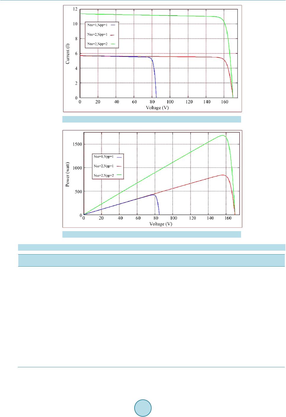 S. B. Asghar, R. K. Singh Figure 15. I-V curve for different values of Nss and Npp. Figure 16. P-V curve for different values of Nss and Npp. Table 1. Parameters value o f PV module. S. No. Parameters Value 1 Voc 85 V 2 Isc 5.68 A 3 Ki 0.0032 A/K 4 Kv −0.1230 V/K 5 Ns 54 6 Nss 1 7 Npp 1 8 Imp 5.4 A 9 Vmp 78.4 V 10 Rs 0.221 ohm By analyzing these results, one can see the effects of partial shading on SPV arrays as future work.  S. B. Asghar, R. K. Singh References [1] Ramos Hernan z, J.A., Campayo Martin, J.J. and Zamora Bel ver, I. (2010 ) Modelling of Photovoltaic Module. Intern a- tional Conference on Renewable Energies & Power Quality. Granada, 23-25 March 2010. [2] Villalva, M.G., Gazoli, J.R. and Filho, E.R. (2009) Comprehensive Approach to Modelling & Simulation of PV Arrays. IEEE Transactions on Power Electronics, 25, 1198-1208. [3] Salmi, T., Bouzguenda, M., Gastli, A. and Masmoudi, A. (2012) Matlab/Simulink Based Modelling of Solar Photovol- taic Cell . International Journal of Renew able En ergy Resear ch, 2. [4] Ghosh, S.K. (2013) Modelling of PV Arrays & Analysis of Different Parameters. International Journal of Advance- ments in Research & Technology, 2, 358-3623. [5] Pongratananukul, N. Analysis & Simulation Tools for SPV Power Systems. PhD Dissertation, University of Central Florida, Orlando. [6] Pandiarajan, N. and Muthu, R. (2011) Mathematical Modelling of Photovoltaic Module with Simulink. International Conference on E lectrical Energy Systems (ICEES 2011), Newport Beach, 3-5 January 2011, 258-263. http://dx.doi.org/10.1109/ICEES.2011.5725339 [7] Khan, B.H. (2009) Non-Conventional Energy Resources. TMH.
|