Journal of Electromagnetic Analysis and Applications
Vol.6 No.7(2014), Article
ID:47450,10
pages
DOI:10.4236/jemaa.2014.67019
Decoupling of Currents in Travelling Wave Induction Heating
Kenneth Frogner, Tord Cedell, Mats Andersson
Division of Production and Materials Engineering, Lund University, Lund, Sweden
Email: kenneth.frogner@iprod.lth.se
Copyright © 2014 by authors and Scientific Research Publishing Inc.
This work is licensed under the Creative Commons Attribution International License (CC BY).
http://creativecommons.org/licenses/by/4.0/


Received 1 April 2014; revised 28 April 2014; accepted 21 May 2014
ABSTRACT
Travelling wave induction heating (TWIH) suffers from severe interference between the coils, which significantly reduces its efficiency. A strategy for decoupling the currents in TWIH is presented, based on the anti-series or anti-parallel connection of several inductors. The study investigates the coupling effect in terms of amplitude and phase shift as functions of current and frequency, respectively, including resonance behavior. In addition, the effects of deviations of the inductor properties are analyzed. Measurements indicate that the strategy produces very good results, almost eliminating the coupling effect, increasing the efficiency, and simplifying control. Simulated and measured results of the heating pattern are compared and efficiency values and power densities are presented.
Keywords:Induction Heating, Inductive Coupling, Decoupling, Travelling Wave, Uniform Heating

1. Introduction
Induction heating has revolutionized many industrial processes in terms of cycle time, energy efficiency, and process accuracy. However, many applications cannot yet benefit from this technology due to their strict requirement for temperature uniformity, which is difficult to achieve using induction heating or other methods. The relatively poor performance of existing heating devices means there is huge potential for improvement, should a technique be developed that enables uniform heating of thin workpieces. In recent years, multiple-coil solutions have proven themselves able to fulfill the demands of these applications, as they give good spatial control of the power generation, permitting uniform temperature distribution. These solutions can be divided into zone-control induction heating (ZCIH) and travelling wave induction heating (TWIH). Significant research effort is spent on coupled induction heating systems with the focus on system modelling; [1] [2] , power electronics; [3] -[5] as well as electromagnetic design and control, [6] [7] etc.
Studies of ZCIH demonstrate that the need for proper control design to achieve good results as well as the importance of maintaining the same current phase angle to prevent interaction that severely reduces the efficiency [4] . A selected combination of frequencies has also been demonstrated to produce good results [8] . In the TWIH system, in contrast, the frequency and phase shift are the keys to achieving the desired heating pattern, providing either high efficiency or uniform heating, unusable in industrial applications. This article aims to demonstrate a way of decoupling the currents, to simplify the control design and provide a solution with high efficiency and good temperature uniformity.
The two-phase TWIH inductor shown in Figure 1 has an inter-coil mutual inductance that is highly dependent on the load. The coupling factor will change depending on the workpiece geometry and material, but also depending on the temperature, excitation frequency, and output power (Figure 2), which makes it difficult to compensate for using a traditional decoupling transformer. This problem can be solved by controlling the decoupling, for example, using power electronics, or by developing a transformer with exactly the same frequency and load dynamics as those of the inductor, which this study aims to do. Connecting two identical inductors in anti-series or anti-parallel, to heat similar workpieces (e.g., in two parallel processes) or the top and bottom sides of a tool, can decouple the currents. Actually a considerable part of the research about TWIH refers to double sided heating [9] -[12] . Running the coils independently of each other prevents the power coming from one variable-frequency drive (VFD) from generating heat in the power electronics driving the other coil, significantly increasing the system efficiency.
This paper presents different ways of decoupling the currents using two identical inductors. The study evaluates the characteristics of each coil and pair of coils to investigate minor variations stemming from their manufacturing and thus potential mismatches. Efficiency values obtained without decoupling are compared with the results after compensation. The influences of excitation frequency, amplitude, and workpiece material are investigated. In addition, the results of the heating pattern at different working points are presented, highlighting the temperature uniformity as well as the effect of deviations in the current phase shift. The measurement results are compared with the simulated values.
2. Travelling Wave Induction Heating
TWIH uses the phase shift between the currents in different coils to generate an electromagnetic field that moves along the workpiece at a speed proportional to the switching frequency. In conjunction with a transverse flux inductor, where the resulting field always cancels itself out and becomes zero at the center, the RMS value of the field from a properly designed TWIH system is fairly uniform over the complete area covered by the coils. “Properly designed” refers to the shape of the inductor geometry, and also to the excitation currents driving the process. For a two-phase system, the optimal current phase shift is close to 90˚, for three-phase it is approximately 120˚, and so on [13] . The greater the number of phases, the smaller the temperature gradients that can be achieved [14] .
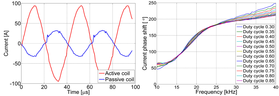
Combining two or more coils in the same inductor unit will give rise to mutual inductance, which creates a coupling problem. Depending on the geometry, flux-concentrating material, type of workpiece, etc., the interaction will change; in the selected system, i.e., a full pitch travelling wave inductor made by litz wire with a soft magnetic moldable composite core [15] , the effect is considerable. Figure 3(a) illustrates the coupling effect at a particular amplitude and frequency, with only one coil being excited. As the amplitude and frequency change, the phase shift of the induced current is significantly affected (see Figure 3(b)). This means that the system becomes difficult to control, as demonstrated by Fujita et al. [4] , and that the efficiency is limited.
3. Analysis
By using two inductors and assuming quasi-static operation, eight unique configurations of serial connections can be identified according to Figure 4, where connections 1 and 4, 2 and 3, 5 and 8, as well as 6 and 7 are expected to behave similarly.
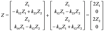
By making a simple model of the voltages, V, and currents, I, within a single inductor, i, the equation system can be formulated as in equation (1), where k represents the complex coupling factors between the two coils, j, each section of which is divided into positive and negative parts depending on the direction of the current. The parts considered are described by the sign indexes of the currents (equation (2)). Z is the impedance felt by each
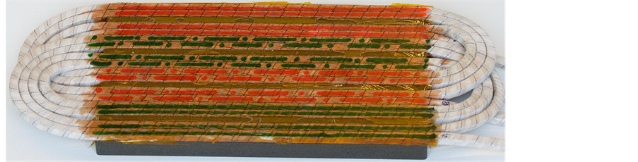
Figure 1. Photo of a two-phase travelling wave inductor.
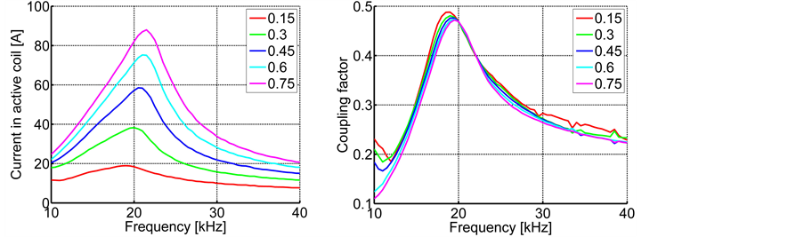
Figure 2. Frequency and voltage amplitude (i.e., duty cycle) dependency: left, current in active coil; right, coupling factor.
 (a) (b)
Figure 3. (a) Coupling effect between coils, coil 1 being excited and coil 2 idle [16] ; (b) Measured phase shift of the current induced by the mutual inductance as a function of frequency and voltage duty cycle.
part of the coil in the inductor, which is considered symmetric.
 (1)
(1)
 (2)
(2)
when connecting two inductors in series, the total voltage equals the sum of voltages according to equation (3).
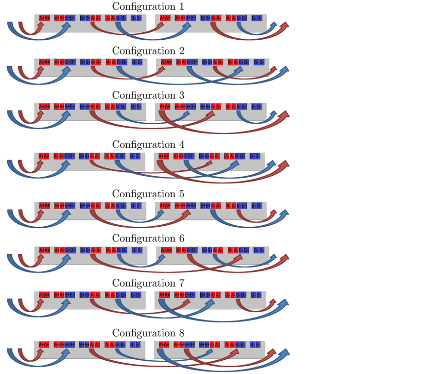
Figure 4. Connection schematics of the eight unique configurations of two two-phase travelling wave inductors, shown in cross-section.
 (3)
(3)
If the inductors are perfectly equal, combining equations (1) and (3) eliminates the coupling factors in configurations 2, 3, 6, and 7 and the coil currents can be controlled separately. In addition, the impedance of the two phases becomes the same. Equations 4 and 5 show the results of configuration 2.
 (4)
(4)
 (5)
(5)
In addition to connecting the two inductors in series, parallel connections can also be made and analyzed in a similar way; for example, configuration 7 connected in parallel appears as shown in Figure 5.

Figure 5. Schematic of configuration 7 connected in parallel mode.
4. Experimental Setup
Two more or less identical two-phase inductors of the type shown in Figure 1 are used in the experiments. The properties of these two inductors and of the two coils in each inductor can be expected to differ slightly due to uncertainties in production. The properties of the coils at low field strength have been measured using an LCR meter (model 8118; Hameg, Mainhausen, Germany).
The inductors are connected to a power electronic platform described in detail by Frogner et al. [16] . The system features two individual VFDs with full-bridge MOSFET outputs, connected via high-frequency transformers and phase-advancing capacitor banks to the inductor setup, schematically depicted in Figure 6. By sending out voltages of different frequencies, amplitudes, and phase shifts, the system can be characterized by measuring the current in each coil and observing the temperature pattern using thermography [17] . The two inductors are located a certain distance from each other to avoid undesired interaction and are completely covered by two black-painted workpieces made of 1-mm-thick, normal quality structural carbon steel (EN 235JRG2).
5. Results and Discussion
The inductance of the different coils was measured, with the workpiece completely covering the inductor at a distance of 4 mm and with the idle coil open. The measurements indicate only small variations in the results, with all four coils within approximately 1.5% of the average inductance (Figure 7). Shorting the idle coil changes the values slightly, but only by 1% - 2% up to 40 kHz. The figure also illustrates the mutual inductance defined by equation (6), where  is the inductance of each coil and k is the coupling between them, which is approximately 20%. In the real setup, however, the coupling factor is significantly dependent on the resonant frequency.
 (6)
(6)
Figure 8 shows the mutual inductance of the eight configurations in series and parallel modes. For configurations 1, 4, 5, and 8, the mutual inductance is doubled or halved, in accordance with the circuit laws of connecting multiple inductances. For configurations 2, 3, 6, and 7, on the other hand, the currents are decoupled, as predicted by theory, and the mutual inductance is significantly reduced. The reduced coupling is evident in all four configurations, but the best results are obtained with configuration 2 followed by configuration 3, as explained by the inductance of the individual coils. The decoupling configurations also display a considerably lower frequency dependence on the mutual inductance than do the other configurations, which confirms that the inductors have similar frequency characteristics, as desired.
By heating with only one of the phases, the level of decoupling can be clearly demonstrated when the inductors are connected in series (Figure 9) as well as in parallel (Figure 10). Configuration 1, with a coupling close to 0.5 at the resonant frequency, yields results similar to those of a single inductor, while in configuration 2 the coupling factor is well below 0.05 at all frequencies (Figure 11).
Assuming that the inductors are perfectly identical and symmetric, the results of the configurations can be summarized as in Table1 The same results are obtained independent of serial,  , versus parallel,
  , connections (as seen in Figure 11), and the type of connection makes no significant difference regarding minor variations,
  , in the inductance between the different coils (equation (7)). The selected inductor is created using only four turns, which makes it sensitive to small variations in the length and position of connection cables, differences in the inputs and outputs, etc. A more robust and, in terms of efficiency, better solution is to use more turns in each coil, made of finer wire.
 (7)
(7)
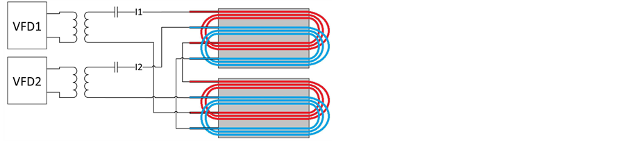
Figure 6. A simplified block diagram of the experimental setup.
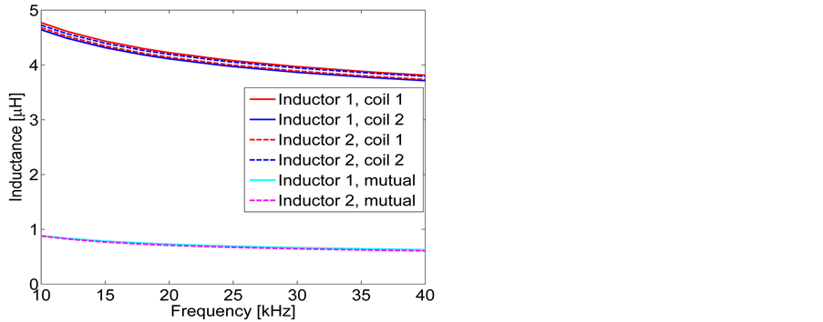
Figure 7. Inductance of the different coils and the mutual inductance of the two pairs of coils.
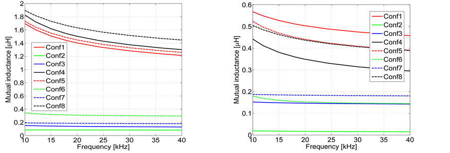
Figure 8. Mutual inductance of the different configurations: left, series; right, parallel.

Table 1. Theoretical results of the different configurations.
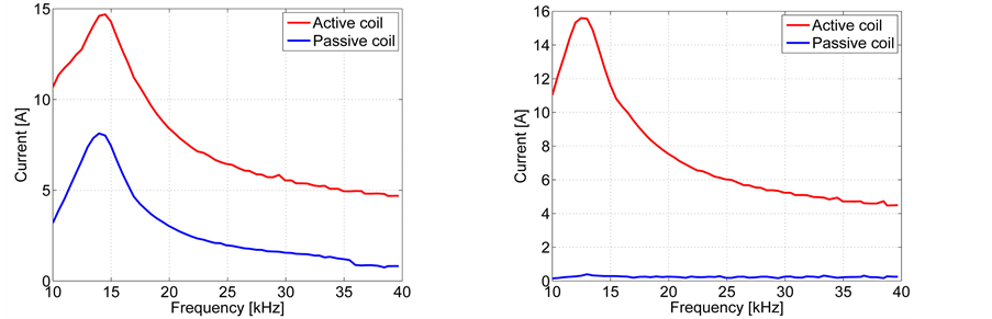
Figure 9. Current in active and passive coils of two inductors connected in anti-series: left, configuration 1; right, configuration 2.
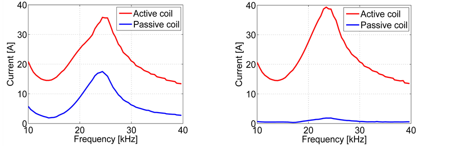
Figure 10. Current in active and passive coils of two inductors connected in anti-parallel: left, configuration 1; right, configuration 2.
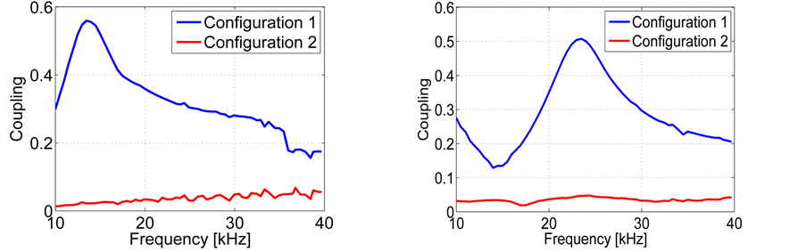
Figure 11. Coupling between the coils in configurations 1 and 2: left, series; right, parallel.
Experimental results indicate efficiency values, from the current in the inductor to heat in the workpiece at a 90˚ phase shift, of approximately 93%. Another 5% - 10% is lost in the power electronics and transformer, depending on the output power, an optimized switching and a nanocrystalline core [18] would significantly improve this.
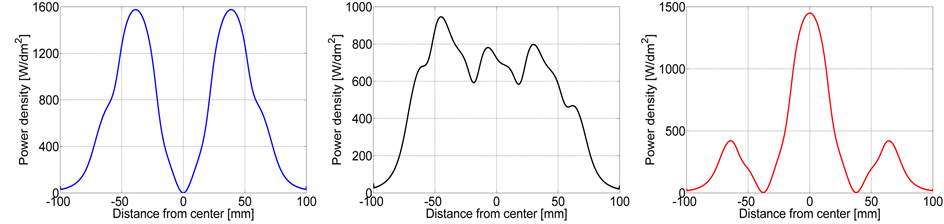
Simulated results based on a 2D planar FEM model (Figure 12), provide the power density along a crosssection of the workpiece heated by the travelling wave inductor at different phase shifts (Figure 13). The modell was built in Finite Element Method Magnetics—FEMM using a bulk model of the litz wire and representative properties of the other materials. To obtain reliable results of the power density along the cross section, the workpiece was divided into small pieces in which the total generated power could be integrated. The width
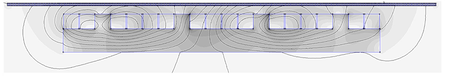
Figure 12. Post-processed planar simulation model of the two phase TWIH at equally sized currents and 90˚ phase shift.
 (a) (b) (c)
Figure 13. Simulated power density in two-phase induction heating using 0˚, 90˚, and 180˚ phase-shifted currents. (a) 0˚; (b) 90˚; (c) 180˚.
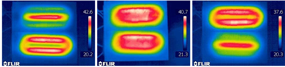
of the inductor was 148 mm and the current in each coil 70 ARMS. The results verify the asymmetric behavior caused by the interference between the coils, examined in the case of three-phase inductors by Dughiero et al. [13] and Ali et al. [19] . The reason to the asymmetry use to be described as differences due to the entry and exit of the wave but is actually dependent on a number of factors; the local coupling between the currents, wire and core geometry as well as the current phase shift and shape. Using the decoupled system, these results can easily be verified experimentally (see Figure 14). At 90˚, as the simulation indicates, the heating pattern close to the coils of the two inductors is fairly uniform, while the workpiece is somewhat warmer in its uppermost parts. In the decoupled system, while one of the inductors has a current phase shift of , the second inductor has a phase shift of
  degrees, which makes the heating results from the two inductors equivalent only at
 .
.
Decoupling the currents significantly simplifies the control, since the current in each coil can be adjusted using the corresponding voltage without affecting the current in the other coil (Figure 15). Instead of part of the current going into one coil generating heat in the VFD connected to the other coil, all of the power is consumed in the processing region, with only small losses in the inductor, as in single-coil systems. However, the uniformity still exacts a certain cost due to the distribution of the magnetic field. The losses appear as an approximately 12% lower output power at constant current compared with zero phase shift shown both by simulations and measurements (Figure 16), however, not significantly reducing the overall efficiency.
6. Summary
In travelling wave induction applications, and in other multi-coil systems suffering from mutual coupling, currents can be efficiently decoupled using two or more identical inductors. The effect is obtained by connecting the different individual inductors either in anti-series or anti-parallel (in theory, both types accomplish the same job). As long as the systems are symmetric and identical, several different configurations will produce the same results, though in practice it might be a good idea to match the coils for the best results. This study succeeded in reducing the coupling factor by approximately 95%. For inductors with more turns in the coils, the compensation becomes less sensitive to variation and even better results can be expected.
The decoupled system has shown efficiency values as high as 93%, calculated from the current in the coils to the energy in the workpiece. The measured heating pattern of the decoupled system coincides well with the simulation results, and a fairly uniform temperature pattern can be achieved in the regions covered by the inductors.
 (a) (b) (c)
Figure 14. Thermographic images of induction heating using 0˚, 90˚, and 180˚ phase excitation and configuration 6. (a) 0˚; (b) 90˚; (c) 180˚.
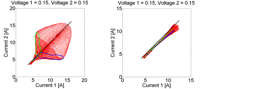
Figure 15. Currents measured in each phase at constant voltage amplitude but at different frequencies and phase shifts. The black line indicates that the currents are equal in amplitude; the green and blue curves indicate a phase shift of ±90˚. Left: configuration 1; right, configuration 2.
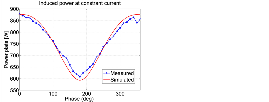
Figure 16. Simulated and measured output power at constant current amplitude but different phase angles.
Acknowledgments
The present research was carried out with the generous support of the Swedish Foundation for Strategic Research (project RaUCH) and as part of the Sustainable Production Initiative (SPI).
References
- Acero, J., Burdío, J.M., Barragán, L.A. and Alonso, R. (2007) A Model of the Equivalent Impedance of the Coupled Winding-Load System for Domestic Induction Heating Application. IEEE International Symposium on Industrial Electronics, Vigo, 4-7 June 2007, 491-496.
- Souley, M., Spagnolo, A., Pateau, O., Paya, B., Hapiot, J., Ladoux, P. and Maussion, P. (2009) Characterization Methodology for the Impedance Matrix of Multi-Coil Induction Heating Device. 6th International Conference on Electromagnetic Processing of Materials EPM, Dresden.
- Rodriguez, J.I. and Leeb, S.B. (2006) A Multilevel Inverter Topology for Inductively-Coupled Power Transfer. IEEE Transactions on Power Electronics, 21, 1607-1617. http://dx.doi.org/10.1109/TPEL.2006.882965
- Fujita, H., Uchida, N. and Ozaki, K. (2011) A New Zone-Control Induction Heating System Using Multiple Inverter Units Applicable under Mutual Magnetic Coupling Conditions. IEEE Transactions on Power Electronics, 26, 2009-2017. http://dx.doi.org/10.1109/TPEL.2010.2101084
- Carretero, C., Lucia, O., Acero, J. and Burdio, J.M. (2013) Computational Modeling of Two Partly Coupled Coils Supplied by a Double Half-Bridge Resonant Inverter for Induction Heating Appliances. IEEE Transactions on Industrial Electronics, 60, 3092-3105. http://dx.doi.org/10.1109/TIE.2012.2202360
- Alotto, P., Spagnolo, A. and Paya, B. (2011) Particle Swarm Optimization of a Multi-Coil Transverse Flux Induction Heating System. IEEE Transactions on Magnetics, 47, 1270-1273. http://dx.doi.org/10.1109/TMAG.2010.2086439
- Pham, H.N., Fujita, H., Uchida, N. and Ozaki, K. (2012) Heat Distribution Control using Current Amplitude and Phase Angle in Zone-Control Induction Heating Systems. Proceedings IEEE Energy Conversion Congress and Exposition (ECCE), Raleigh, 15-20 September 2012, 2474-2481. http://dx.doi.org/10.1109/ECCE.2012.6342403
- Barragan, P.L.A., Burdío, P.J.M., Hernandez, B.P., Llorente, G.S., Lorente, P.A. and Monterde, A.F. (2007) Method for Operating Converter Circuit. Patent WO2005/043737A3.
- Qaseer, L.J.B. (2010) Analysis of Double and Single Sided Induction Heating Systems by Layer Theory Approach. Journal of Electromagnetic Analysis & Applications, 2, 403-410. http://dx.doi.org/10.4236/jemaa.2010.27052
- Wang, J., Wang, Y., Ho, S.L., Yang, X., Fu, W.N. and Xu, G. (2011) Design and FEM Analysis of a New Distributed Vernier Traveling Wave Induction Heater for Heating Moving Thin Strips. IEEE Transaction on Magnetics, 47, 2612-2615. http://dx.doi.org/10.1109/TMAG.2011.2154379
- Ho, S.L., Wang, J., Fu, W.N. and Wang, Y.H. (2009) A Novel Crossed Travelling Wave Induction Heating System and Finite Element Analysis of Eddy Current and Temperature Distribution. IEEE Transactions on Magnetics, 45, 4777-4780. http://dx.doi.org/10.1109/TMAG.2009.2021667
- Wang, Y., Wang, J., Pang, L., Ho, S.L. and Fu, W.N. (2011) An Advanced Double-Layer Combined Windings Transverse Flux System for Thin Strip Induction Heating. Journal of Applied Physics, 109, Article ID: 07E511.
- Dughiero, F., Lupi, S. and Siega, P. (1995) Analytical Calculation of Double Sided Travelling Wave Induction Heating Systems. COMPEL, 14, 251-255. http://dx.doi.org/10.1108/eb051951
- Dughiero, F., Lupi, S., Nemkov, V. and Siega, P. (1994) Travelling Wave Inductors for the Continous Induction Heating of Metal Strips. Proceedings of the 7th Mediterranean Electrotechnical Conference, 3, 1154-1157. http://dx.doi.org/10.1109/MELCON.1994.380864
- Svensson, L., Frogner, K., Cedell, T., Jeppsson, P. and Andersson, M. (2012) Soft Magnetic Moldable Composites— Properties and Applications. Journal of Magnetism and Magnetic Materials, Elsevier.
- Frogner, K., Cedell, T. and Andersson, M. (2014) Induction Heating Using a Two-Phase Travelling Wave Setup. Internatinal Journal of Applied Electromagnetics and Mechanics, 44, 217-226.
- Frogner, K., Cedell, T. and Andersson, M. (2012) A Method for Fast Characterization of Power Efficiency in Induction Heating Processes. Proceedings of the Swedish Production Symposium, Sweden.
- Nikolov, G.T. and Valchev, V.C. (2009) Nanocrystalline Magnetic Materials versus Ferrites in Power Electronics. Procedia Earth and Planetary Science, 1, 1357-1361.
- Ali, A., Bukanin, V., Dughiero, F., Lupi, S., Nemkov, V. and Siega, P. (1994) Simulation of Multiphase Induction Heating Systems. Proceedings of the 2nd International Conference on Computation in Electromagnetics, UK, 211-214. http://dx.doi.org/10.1049/cp:19940054