Journal of Electromagnetic Analysis and Applications
Vol.5 No.5(2013), Article ID:31728,4 pages DOI:10.4236/jemaa.2013.55035
Finite Element Methods Applied to the Tubular Linear Stepping Motor
![]()
Unité de Recherche en Automatique et Informatique Industrielle de l’Institut National des Sciences Appliquées et de Technologie, Tunis, Tunisie.
Email: walidfezzani@gmail.com
Copyright © 2013 Walid El Fezzani, Abdessattar Ben Amor. This is an open access article distributed under the Creative Commons Attribution License, which permits unrestricted use, distribution, and reproduction in any medium, provided the original work is properly cited.
Received January 20th, 2013; revised February 21st, 2013; accepted March 5th, 2013
Keywords: Finite Element Methods; Linear Tubular Stepping Actuator; Mesh Repartition
ABSTRACT
In this paper proposes a Finite Element Methods analyzing applied to the linear tubular stepping actuator. The linear displacement is modeled by means of a layer of finite elements placed in the air gap. The design of the linear stepper motor for achieving a specific performance requires the choice of appropriate tooth geometry. The magnetic field of the actuator has been analyzed using the finite element method over a current-displacement variation. The magneto static field and electromagnetic force was introduced in order to predict before construction, the inductance values according to the displacement and the currents into the coils. The results were obtained for the magnetic flux density distribution and the electromagnetic force for different positions and current.
1. Introduction
Linear motors can be employed in several applications as pumps and linear actuator, and several domains of technologies [1]. The linear motor studied in this paper is a linear tubular stepping actuator with a switched reluctance structure as it’s shown in Figure 1.
Among the numerous methods of electromagnetic modeling, the finite element method is a reference one which is imperative due to the precision of the results [2].
Moreover, the FEM is a good tool to predict and to find approached solution for electromagnetic problems [3].
In addition, this numerical method is a widely used method for the study of irregular and not homogeneous machines geometries [4].
The motor studied is composed of four coils, three nonmagnetic separations between the coils and a mover.
In this paper, the study uses a finite element solver with the commercial software Magnet from Infolytica cooperation.
2. FEM Analyze of a Simple Module of the Linear Tubular Stepping Motor
The FEM analysis is essential to analyze the flux and the magnetic density in different part of the motor [5]. In this part, we will study the 2D and the 3D FEM analysis of a simple module (one phase per time).
The numeric field analysis was performed by the software Magnet from Infolytica Corporation, using this FEM analysis we can determine the magnetic field “B” and the magnetic flux “Φ” with means of the 2D and the 3D design, it’s helpful and useful to predict the repartition and the sense of the magnetic field before we start the real mechanical conception [6].
In the Figure 2(a), a simple module is shown to present one phase. Then, in the Figure 2(b), when the coil is energized, we observe the flux distribution in both of the stator and mover module. In the Figure 2(c), a 3D mesh

Figure 1. Model design of the linear tubular stepping actuator.
repartition is necessary in the FEM analyzing to computing correctly the different magnetic characteristics [4]. Finally, in the Figure 2(d), the FEM analyzing permits to computing the magnetic density in different zone of the simple module. In the air gap, the red color is a proof that the flux density is well canalized between the stator module and the mover [7].
In this part, we will focus on a four modules of the linear hybrid stepping motor but first a study of a simple module and its different constitutions is detailed below.
The simple module is composed of:
1) A mobile rotor moving horizontally, the displacement called step depending on the algebric current value that excites the coil [8]. The material used to construct the rotor is “Cold rolled 1010 steel” (CR10).
2) A fix stator has the same material as the rotor, the stator module composed of one coil. The coil material is Copper (5.77e7 Siemens/meter) and has 200 turns.
3) An air gap between the toothed structure of both of the rotor and the stator in order to eliminate the mechanical losses due to the friction and must be as minimum as possible to canalize the flux density into the tooth structure [9].
4) A non-magnetic separation placed between two successive stators.
The previous study turned around the determination and the prediction of the magnetic field and the flux density distribution. In the fact, the static study of the doubly
 (a)
(a)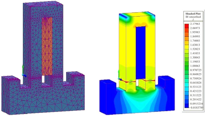 (b)
(b)
Figure 2. (a) 3D simple module design; (b) Flux density distribution; (c) Mesh repartition; (d) Magnetic field.
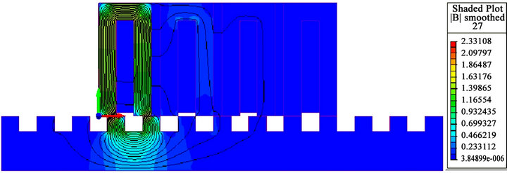
salient machines such the linear switched stepping motor, required an interest around the teeth structure of both of the stator and the rotor, especially in the air gap zone taken here 0.1 mm as dimension [8]. In this air gap zone an FEM computation of the magnetic field and the flux value distribution is shown in the figures below (Figures 3(a)-(d)) to predict the value of the flux and the magnetic field when the coil is energized under 2 A.
When the phase A is energized, the flux lines flows through the stator module B and C and crossing the air gap into the mover. As it shown in the follows figures below, few flux lines dissipate into the stators modules neighbors.
Basing on the FEM analyze, the magnetic field value varies from 0 T (color blue) to 1.7 T (yellowish green)
The figures below shows the phase excitation of phase A, phase B, phase C and phase D in respectively Figures 3(a)-(d).
 (a)
(a)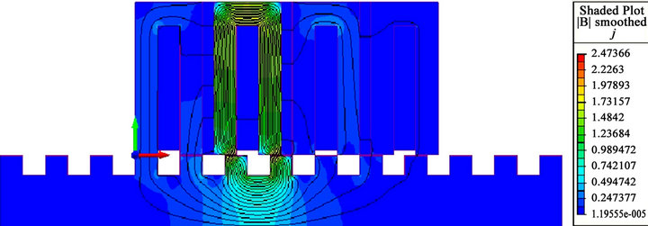 (b)
(b)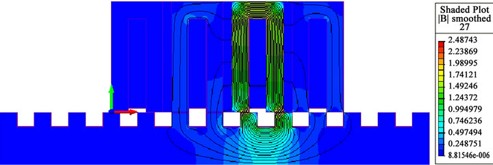 (c)
(c) (d)
(d)
Figure 3. (a) Phase excitation A; (b) Phase excitation B; (c) Phase excitation C; (d) Phase excitation D.
The finite element method allows finding approached solution for electromagnetic problems as a field defined on sub-domains (meshes) constituting the hall study domain containing the actuator. The approximate solution is completely determined from the values taken by the solution at the different mesh nodes [10].
In FEM analyzing, it’s important to choose the right mesh in order to calculate the right values of the magnetic field and flux density as forces. A good mesh refining in the motor model and especially in the air gap provides with greater certainty and precision the characteristics of the motor as it shown in the Figure 4 [11].
Studying the material of the linear actuator is essential to know their magnetic permeability and property. The material chosen of the mover and the stator is the cold rolled steel 1010. The magnetic permeability curve B = f(H) allows to study the magnetization characteristic of the material as shown in the Figure 5.
This curve has three distinct regions: the steep initial part of the curve, where a small increase in H produces a large increase in B; the knee of the curve; and the saturated region beyond the knee, where a large increase in H is required for any perceptible increase in B. With this material, a flux density of about 2.2 T marks the onset of saturation.
In the previous FEM analyze of the linear tubular stepping actuator, the first step of 2.54 mm will be studied when phase coil B is energized in order to calculate with

Figure 4. Mesh refining.
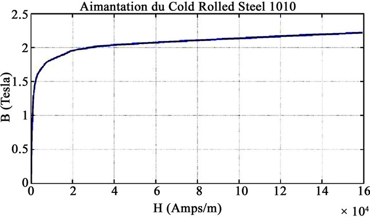
Figure 5. Magnetic permeability of the cold rolled steel.
the software Magnet from Infolytica Corporation, the tangential thrust force, the magnetic and the flux density versus the current and the displacement variation. With the FEM analyzing we can also calculate the inductance and the coil resistance [12].
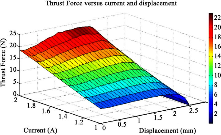
The tangential force called too thrust force is in terms of current and position [13]. The Figures 6(a) and (b) show the thrust force versus position and current. The position varies from 0 mm to 2.54 mm, the current values varies from 1 A to 2 A. In the initial position, both of the mover and stator teeth are opposed in the middle and this correspond to a zero position. When the mover reaches a position of 2.54 mm, both of the teeth (mover and stator) are totally unaligned. The maximum trust force reached is 23 N when the current is equal to 2 A and for a position of 1.6 mm. The minimum thrust force reached is 0 N and that corresponds to an aligned position of both of the mover and stator teeth [14].
As shown in Figure 7, as the current increases, the inductance decreases drastically. When the teeth were opposite in the middle, and for a fixed current equal to 2 A, the inductance L is equal to 0.061 H. For the same current value, when the teeth were unaligned, the inductance value is equal to 0.043 H.
 (a)
(a)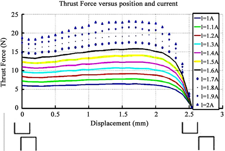 (b)
(b)
Figure 6. (a) Thrust Force versus position and current, 3D plot; (b) Thrust Force versus position and current, 2D plot.
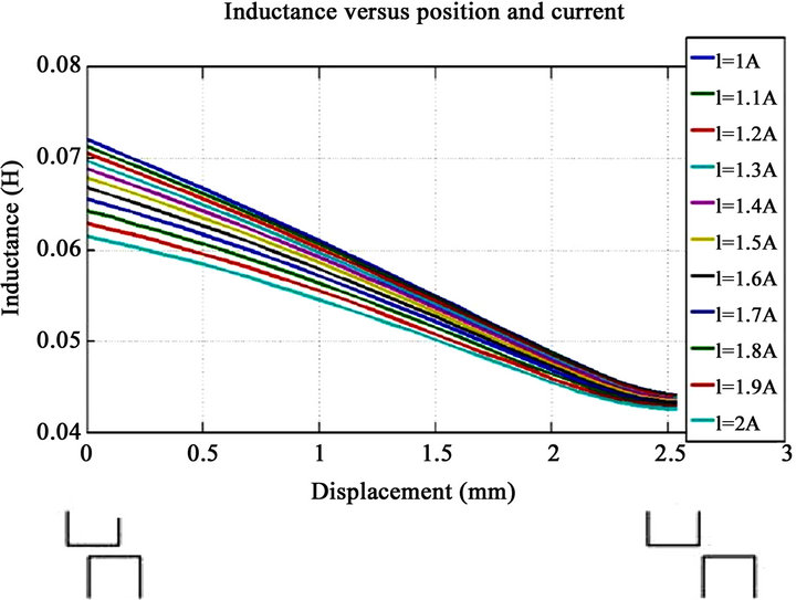
Figure 7. Inductance versus position and current.
3. Conclusion
The Finite Element Method is necessary before the motor design and construction. It is essential to know the magneto static field and electromagnetic force for different position. In order to get the right values as forces and inductances with different position and current, we should first study the simple stator module then to determine the magnetic flux lines into the air gap by exciting the coil one per one. Finally a good mesh repartition provides more accurate results.
REFERENCES
- D. Deás , P. Kuo-Peng, N. Sadowski, A. M. Oliveira, J. L. Roel and J. P. A. Bastos, “2-D FEM Modeling of the Tubular Linear Induction Motor Taking into Account the Movement,” IEEE Transactions on Magnetics, Vol. 38, No. 2, 2002, pp. 1165-1168. doi:10.1109/20.996298
- S. McFee and J. P. Webb and D. A. Lowther, “A Tunable Volume Integration Formulation for Force Calculation in Finite-Element Based Computational Magnetostatics,” IEEE Transactions on Magnetics, Vol. 24, No. 1, 1988, pp. 439-442. doi:10.1109/20.43951
- A. E. Santo, M. R A. Calado and C. M. P. Cabrita, “Dynamic Simulation of Electromagnetic Actuators Based on the Co-Energy Map,” The 16th IASTED International Conference on Applied Simulation and Modelling, Palma De Mallorca, 29-31 August 2007, pp. 509-514.
- M. R. A. Calado, A. E. Santo, S. J. P. S. Mariano and C. M. P. Cabrita, “Characterization of a New Linear Switched Reluctance Actuator,” International Conference on Power Engineering, Energy and Electrical Drives, Lisbon, 18-20 March 2009, pp. 315-320. doi:10.1109/POWERENG.2009.4915253
- A. E. V. do Espirito Santo, M. do R. Calado and C. M. P. Cabrita, “Design and Evaluation of a Linear Switched Reluctance Actuator for Positioning Tasks,” Turkish Journal of Electrical Engineering & Computer Sciences, Vol. 18, No. 6, 2010, pp. 925-942.
- D. S. B. Fonseca, T. J. B. Godinho and C. P. Cabrita, “Electromagnetic Characterization of a Linear Reluctance Actuator: A New Approach,” International Conference on Electrical Machines, Vilamoura, 6-9 September 2008, pp. 1-6. doi:10.1109/ICELMACH.2008.4800225
- J.-F. Llibre, N. Martinez, B. Nogarède and P. Leprince, “Linear Tubular Switched Reluctance Motor for Heart Assistance Circulatory Analytical and Finite Element Modeling,” 10th International Workshop on Electronics, Control, Measurement and Signals (ECMS), Liberec, 1-3 June 2011, pp. 1-6. doi:10.1109/IWECMS.2011.5952367
- A. Ben Amor, “Experimental Identification of a Linear Tubular Four Phase Stepping Motor,” 2002 IEEE International Conference on Systems, Man and Cybernetics, Vol. 5, 2002. doi:10.1109/ICSMC.2002.1176431
- P. Acarnley, “Stepping Motors a Guide to Theory and Practice,” 4th Edition, The Institution of Engineering and Technology, London, 2002.
- L. El Amraoui, “Use of Inverse Models Built for Accurate Microstepping of Linear Switched Reluctance Step Actuators,” IMACS Multiconference on “Computational Engineering in Systems Applications” (CESA), Beijing, 4-6 October 2006.
- I. Yatchev, K. Hinov and V. Gueorgiev, “3D Finite Element Modelling of a Permanent Magnet Electromagnetic Valve Actuator,” Annals of the University of Craiova, Electrical Engineering Series, No. 32, 2008.
- A. Mosallanejad and A. Shoulaie, “Calculation of Coil Inductance in Tubular Linear Reluctance Motor using Three Dimensional FEM,” Przegląd Elektrotechniczny (Electrical Review), 2011.
- L. M. Pestana, M. do R. Calado and S. Mariano, “Speed Control Scheme Analysis of Switched Reluctance Actuator,” Przegląd Elektrotechniczny (Electrical Review), 2012.
- J. Corda and M. Wilkinson, “Modelling of Static Thrust Characteristics of Cylindrical Linear Switched Reluctance Actuator,” Seventh International Conference on Electrical Machines and Drives, Durham, 1-13 September 1995, pp. 354-358.