Journal of Electromagnetic Analysis and Applications
Vol.4 No.4(2012), Article ID:18618,5 pages DOI:10.4236/jemaa.2012.44024
Simulation of Dual-Band MWCNT Ink-Based Spiral Antenna: A Comparative Study
![]()
1Faculty of Electronic Engineering, Menoufia University, Menouf, Egypt; 2National Telecom Regulatory Authority, Cairo, Egypt; 3Shobraa Faculty of Engineering, Benha University, Cairo, Egypt; 4RF/Microwave and Photonics Group, Department of Electrical and Computer Engineering, University of Waterloo, Waterloo, Canada.
Email: m_soliman23@hotmail.com
Received February 15th, 2012; revised March 16th, 2012; accepted March 25th, 2012
Keywords: Copper; MWCNT; CST MWS; ADS and Spiral Microstrip Antenna
ABSTRACT
In this paper, we compare a dual-band, square spiral microstrip patch antenna constructed from Multi-Walled Carbon Nanotubes (MWCNT) ink for wearable application simulated by Computer Simulation Technology Microwave Studio (CST MWS) by our work simulated by Advanced Design System (ADS) electromagnetic simulator using the same material characterization. The reflection coefficient is –12 dB at 1.2276 GHz for MWCNT and –13 dB at 1.25 GHz for the copper simulated by CST MWS and reflection coefficient is –12.235 dB at 1.234 GHz for MWCNT and –18.36 dB at 1.243 GHz for the copper simulated by ADS and the reflection coefficient is –27dB at 2.47 GHz for MWCNT and –13 dB at 2.53 GHz for the copper simulated by CST MWS and the reflection coefficient is –26.08 dB at 2.48 GHz for MWCNT and –17.031 dB at 2.47 GHz for the copper simulated by ADS. We show the meandering of the surface current on the radiating in spiral patch. The antenna gain is found to be –12.5 dBi at 1.22 GHz for MWCNT and is found –12.05 dBi at 1.25 GHz at CST MWS and the antenna gain is found to be –11.85 dBi at 1.235 GHz for MWCNT and is found –12.25 dBi at 1.243 GHz at ADS and the antenna gain is found to be –4.25 dBi at 2.47 GHz for MWCNT and is found –4.01 dBi at 2.53 GHz at CST MWS and the antenna gain is found to be –4.23 dBi at 2.47 GHz for MWCNT and is found –4.88 dBi at 2.45 GHz at ADS. We show a close agreement in the results obtained by the two simulation software's CST MWS and ADS. The results are given for both MWCNT and Copper characterizations.
1. Introduction
Using MWCNT ink [1] instead of copper for microstrip patch antenna gives main benefits against copper. These advantages are lower mass density and high resistivity against corrosion [2,3], the two simulators CST MWS and ADS are used to evaluate the return loss, matching impedance, resonant frequency, bandwidth and far field radiation patterns.
This paper is organized as follows, in Section 2, we present a condense overview about both CST MWS and ADS. In Section 3 we present the MWCNT ink parameters, antenna design, and simulations used in this comparative study. Finally the paper is concluded in Section 4.
2. Simulation Overview
CST MWS [4], the microwave simulator, which is based on Method of Demand (MoD) approach which allows using the simulator or mesh type that is best suited to a particular problem, applying these highly advanced techniques normally increases the accuracy of simulation substantially in comparison to conventional simulators.
Since no method works equally well in all application domains, the software contains four different simulation techniques (transient solver, frequency domain solver, integral equation solver and eigenmode solver) to best fit their particular applications. The frequency domain solver also contains specialized method for analyzing highly resonant structure such as filters. Furthermore, the frequency domain solver supports both hexahedral and tetrahedral mesh types.
The most fixable tool is the transient solver, which can obtain the entire broadband frequency behavior of the simulated device from only one calculation run (in contrast to the frequency step approach of many other simulators). This solver is remarkably efficient for most kinds of high frequency applications such as connectors, transmission line, filters, antenna and more.
The transient solver is less efficient for electrically small structures that are much smaller than the shortest wavelength. In these cases it is advantageous to solve the problem by using the frequency domain solver. The frequency domain solver may also be the method of choice for narrow band problems such as filters or when the usage of tetrahedral grids is advantageous. Besides the general purpose solver (supporting hexahedral and tetrahedral grids), the frequency domain solver also contains fast alternatives for the calculation of S-parameters for strongly resonating structures. Please note that the latter solvers are currently available for hexahedral grids only.
For electrically very large structures, volumetric discretization methods generally suffer from dispersion effects which require very fine meshes. CST MICROWAVE STUDIO® therefore contains an integral equation based solver which is particularly suited to solving this kind of problems. The integral equation solver uses a triangular surface mesh which becomes very efficient for electrically large structures. The MLFMM solver technology ensures an excellent scaling of solver time and memory requirements with increasing frequencies.
Efficient filter design often requires the direct calculation of the operating modes in the filter rather than an S-parameter simulation. For these applications, CST MICROWAVE STUDIO® also features an eigenmode solver which efficiently calculates a finite number of modes in closed electromagnetic devices. If you are unsure which solver best suits your needs, contact your local sales office for further assistance.
Each solver's simulation results can be visualized with a variety of different options. Again, a strongly interactive interface will help you achieve the desired insight into your device quickly. The last—but not least—outstanding feature is the full parameterization of the structure modeler, which enables the use of variables in the definition of your component. In combination with the built-in optimizer and parameter sweep tools, CST MICROWAVE STUDIO® is capable of both the analysis and design of electromagnetic devices.
Agilent Advanced Design System (ADS) [5] is an industry standard microwave engineering computer-aideddesign (CAD) program. Agilent ADS allows microwave engineers to analyze, design, and simulate active and passive microwave components and systems. A microstrip transmission line will be designed and analyzed. It should be noted that there are two ways to design/simulate in Agilent ADS; schematic (equation-based) or fullwave (Method-of-Moments).
The growing number and complexity of high frequency systems is leading to an increased need for electromagnetic (EM) simulation to accurately model larger portions of the system. There are several different technical approaches to EM simulation, and while no method is generally superior to the others, each one of them is aligned with one or more application areas. This article will discuss the three most established EM simulation technologies: Method-of-moments (MoM), finite element method (FEM) and finite difference time domain (FDTD), linking the simulation technology to solving specific applications.
Among all techniques to solve EM problems, the method of moments (MoM) is one of the hardest to implement because it involves careful evaluation of Green’s functions and EM coupling integrals. Maxwell’s equations are transformed into integral equations which upon discretization yield the coupling matrix equation of the structure. The advantage of this transform is that the current distributions on the metal surfaces emerge as the core unknowns. This is in contrast to other techniques which typically have the electric and/or magnetic fields (present everywhere in the solution space) as the core unknowns. Only the surfaces of the metals, where the currents flow, need to be taken into account in the meshing. Hence the number of unknowns (or the size of the matrix) is much smaller. This results in a very efficient simulation technique, able to handle very complex structures.
This benefit comes with a price as the integral equations are not applicable for general 3D structures. The key is the availability of the Green’s functions. Computation of the Green’s functions is only available for free space or for structures that fIt in a layered stack up. These so-called 3D planar structures can have any shape in the plane of the layered stack, but can only have vertical geometry features (via’s) in the normal direction. Many practical RF or microwave structures fall into this category. Hence the method of moments is a very widespread technique and commonly used for the simulation of printed antenna’s, MMIC’s, RF boards, SiPs, RFIC, SI structures and RF modules.
3. Antenna Design and Simulations
The patch is shaped as a square spiral trace truncated horizontally on a lossy FR4 substrate with a relative permittivity of 2.5, a loss tangent of 0.018 and thickness of 0.5 mm The 50 Ω feeding point for the copper for the MWCNT ink, possessing an electrical conductivity of 2.2 × 10⁴ S/m and relative permittivity of 5-j1 respectively.
Figure 1 shows the MWCNT and Copper antenna simulation the simulated by CSTMWS. Figure 2 shows the MWCNT and copper antenna simulated by ADS.
The authors were familiar with the ADS simulators in designing both compact dual-band micrstrip patch array antenna and steerable dual-band planer microstrip phased array antenna for both 3G and 4G wireless communications systems [6,7].
A dual-band, square spiral microstrip patch antenna constructed from (MWCNT) Multi-Walled Carbon Nanotubes ink deposited on a thin flexible FR4 substrate
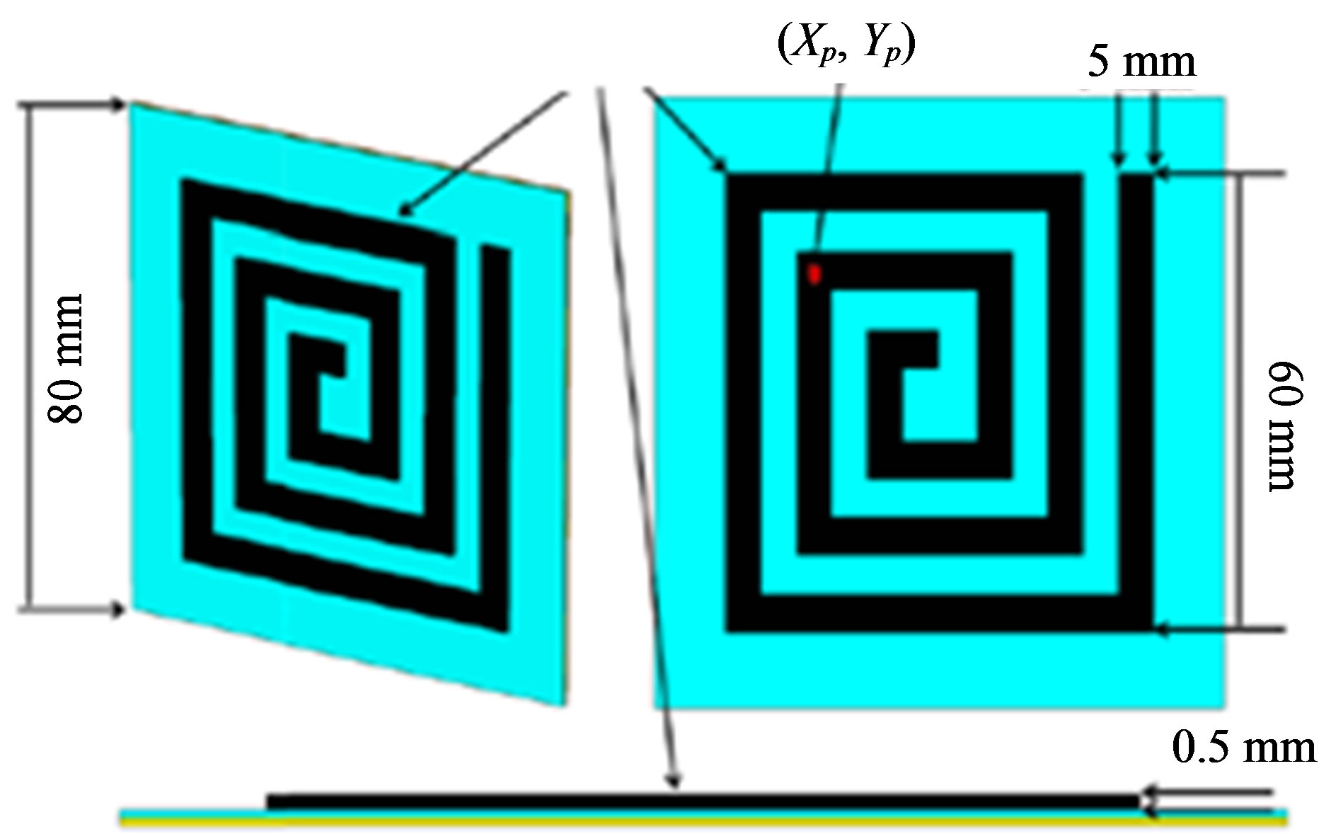
Figure 1. Geometry of MWCNT and copper spiral antenna element simulated by CST MWS.
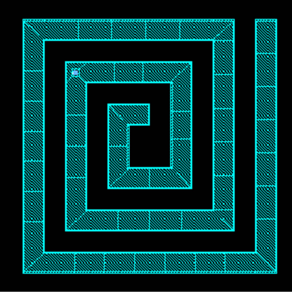
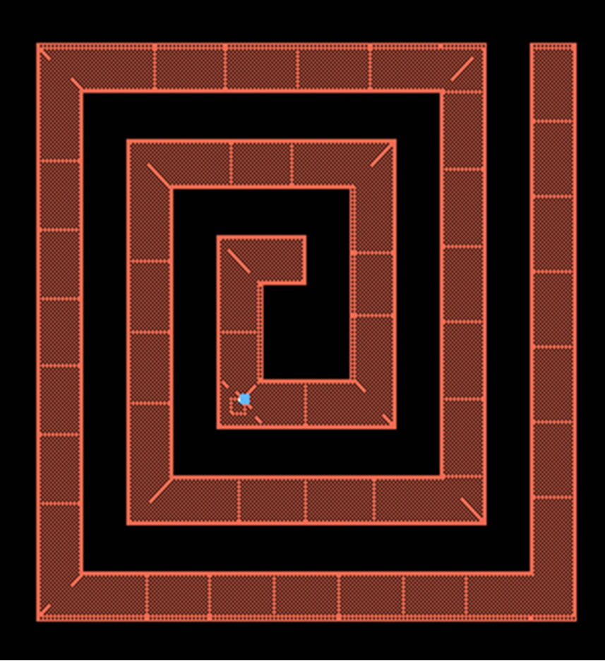
Figure 2. Geometry of MWCNT and copper spiral antenna element simulated by ADS.
the propose antenna operates at 1.22 GHz for wearable Global Position System applications and 2.47 GHz for wearable Multichannel Multipoint Distribution Services. Figure 3 shows the reflection coefficient is –12 dB at 1.2276 GHz for MWCNT and –13 dB at 1.25 GHz for the copper simulated by CST MWS. Figure 4 shows the reflection coefficient is –12.235 dB at 1.234 GHz for MWCNT and –18.36 dB at 1.243 GHz for the copper simulated by ADS.
Figure 5 shows the reflection coefficient is –27 dB at 2.47 GHz for MWCNT and –13 dB at 2.53 GHz for the copper simulated by CST MWS. Figure 6 shows the reflection coefficient is –26.08 dB at 2.48 GHz for MWCNT and –17.031 dB at 2.47 GHz for the copper simulated by ADS. Figure 7 shows Meandering of the surface current on the radiating in spiral patch.
Figure 8 shows the antenna gain is found to be –12.5 dBi at 1.22 GHz for MWCNT and is found –12.05 dBi at 1.25 GHz at CST MWS. Figure 9" target="_self"> Figure 9 shows the antenna gain is found to be –11.85 dBi at 1.235 GHz for MWCNT and is found –12.25 dBi at 1.243 GHz at ADS. Figure 10 shows the antenna gain is found to be –4.25 dBi at 2.47 GHz for MWCNT and is found –4.01 dBi at 2.53 GHz at CST MWS. Figure 11 shows the antenna gain is found to be –4.25 dBi at 1.246 GHz for MWCNT and is found –12.95 dBi at 1.247 GHz at ADS.
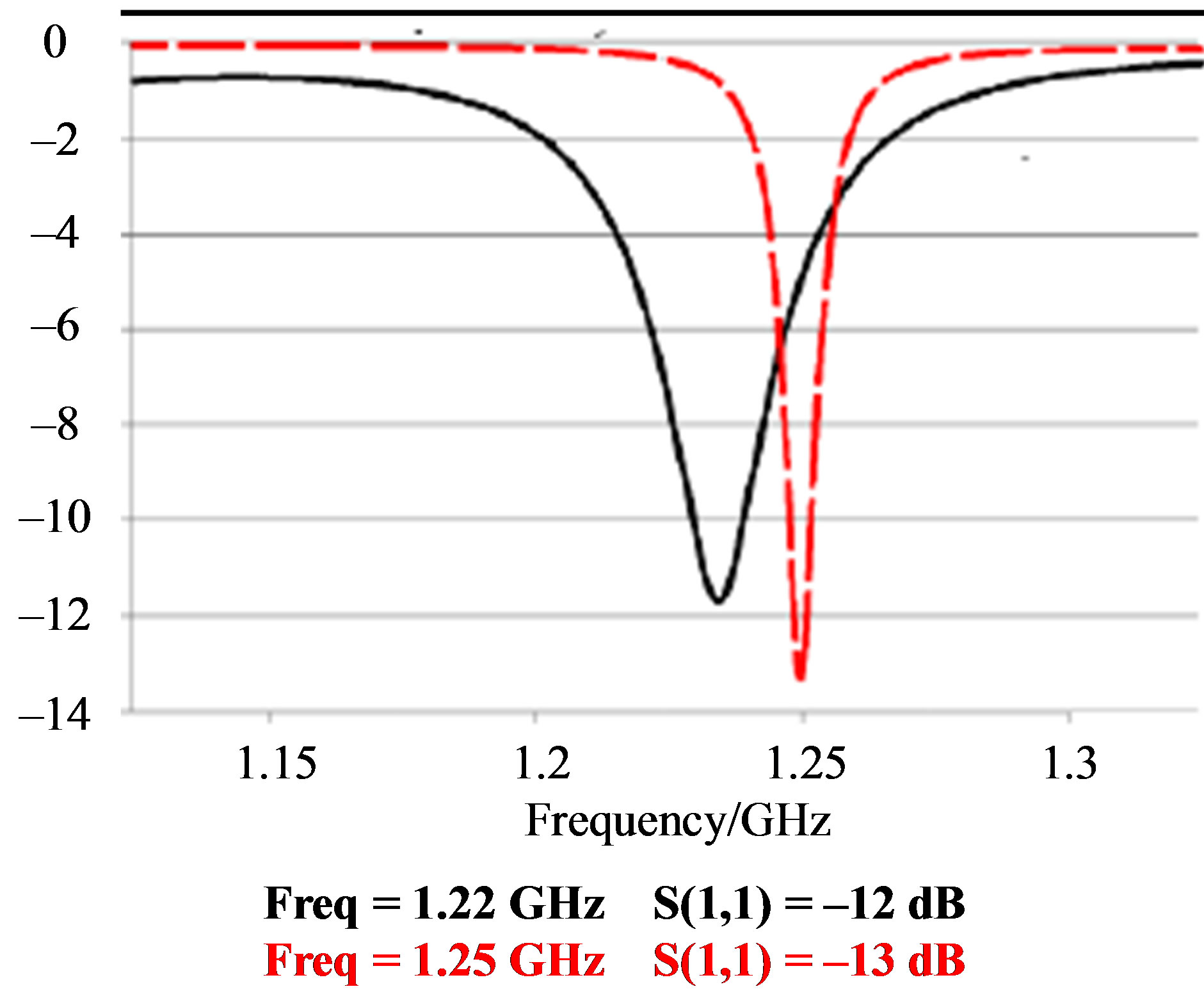
Figure 3. Reflection coefficient S11 of MWCNT and copper spiral antenna simulated by CST MWS.
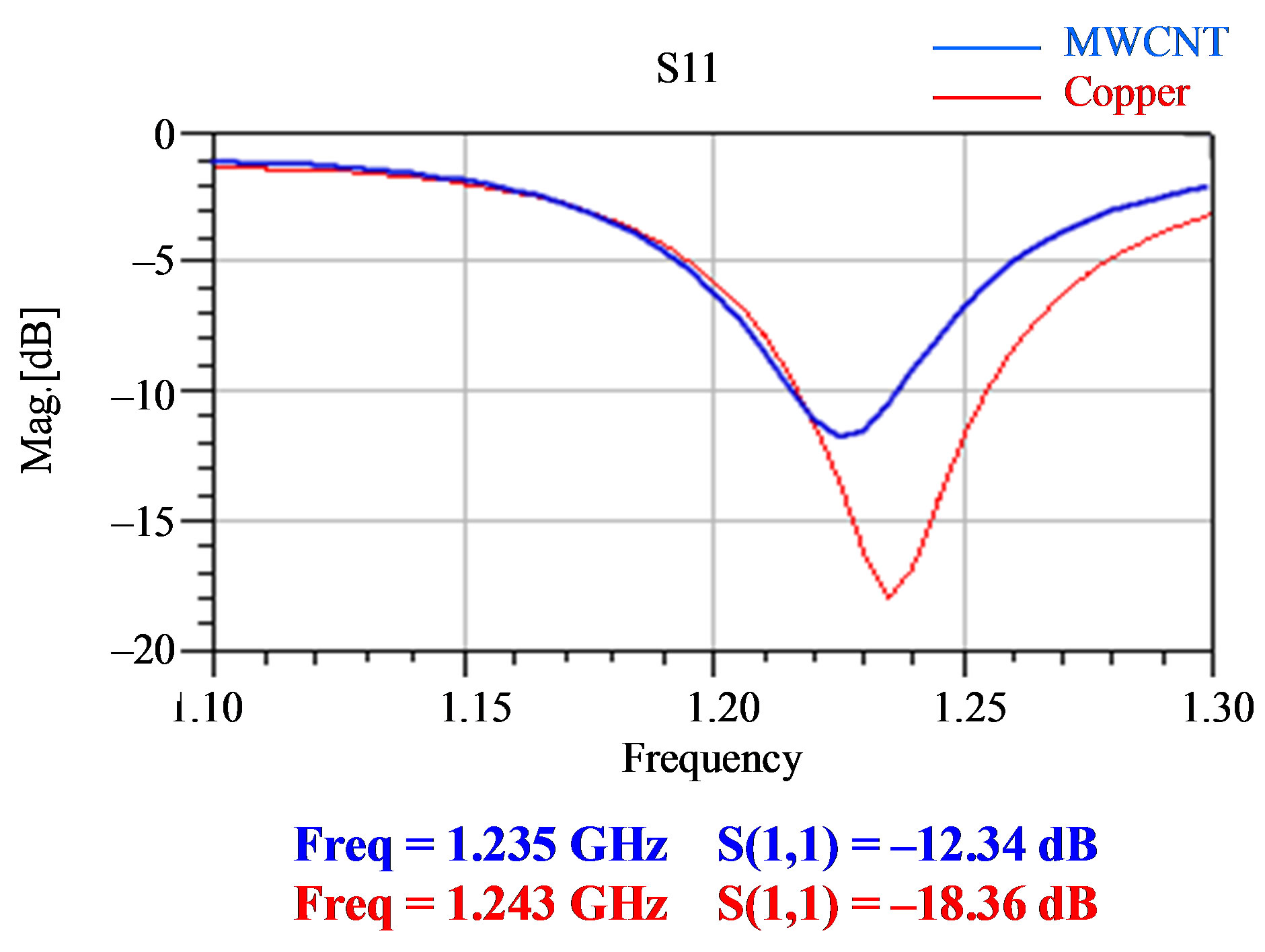
Figure 4. Reflection coefficient S11 of MWCNT and copper spiral antenna simulated by ADS.
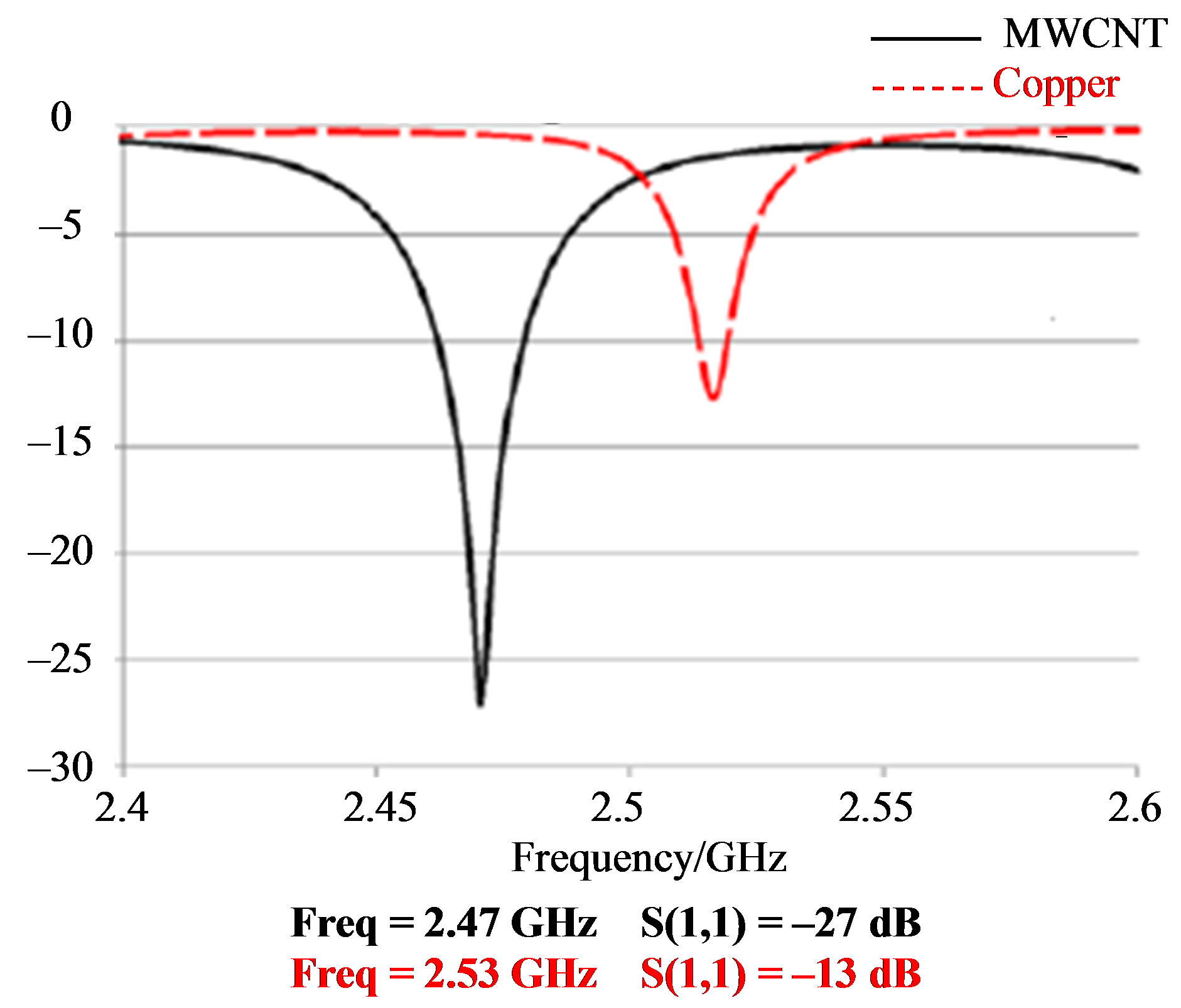
Figure 5. Reflection coefficient S11 of MWCNT and copper spiral antenna simulated by CST MWS.
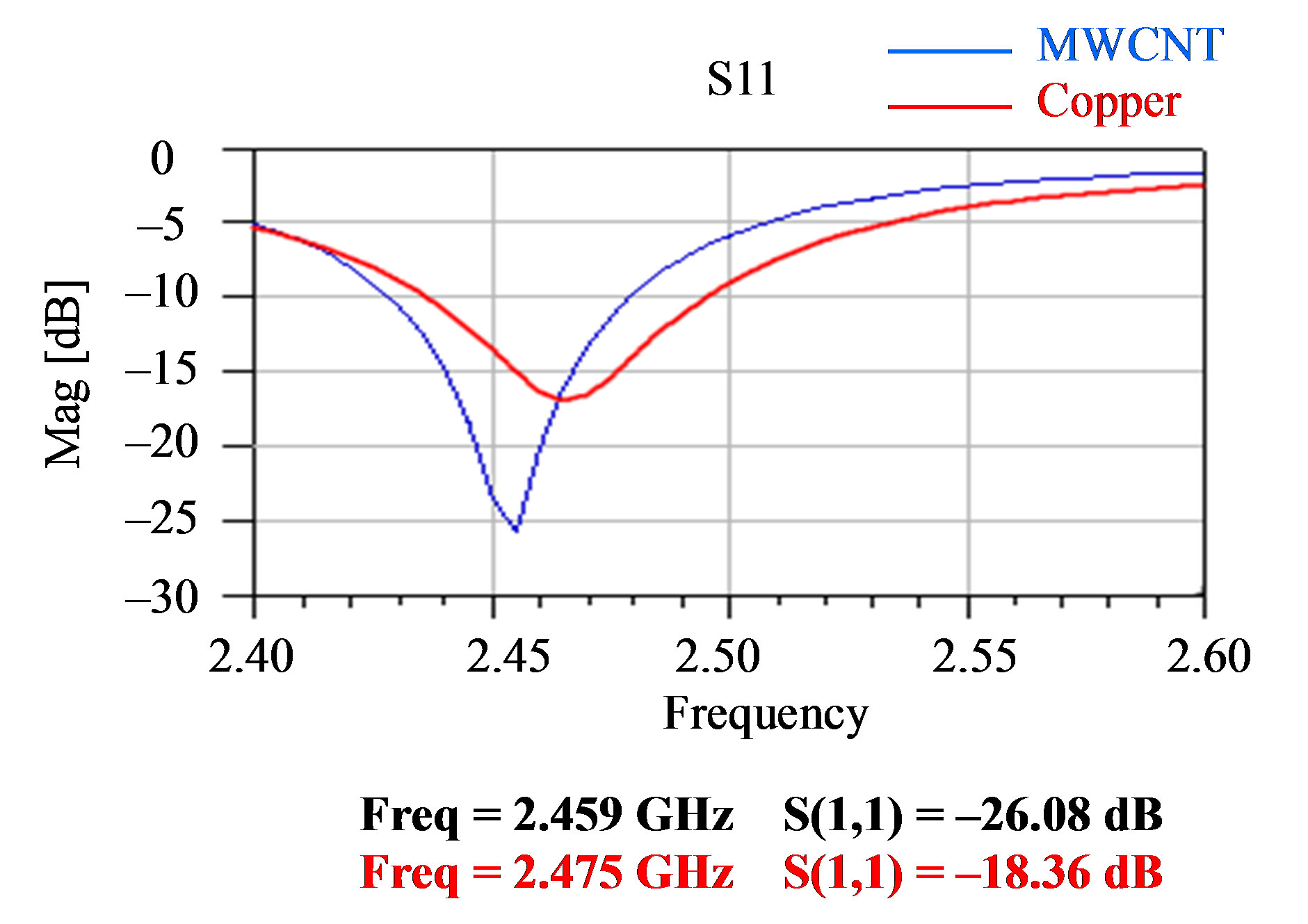
Figure 6. Reflection coefficient S11 of MWCNT and copper spiral antenna simulated by ADS.
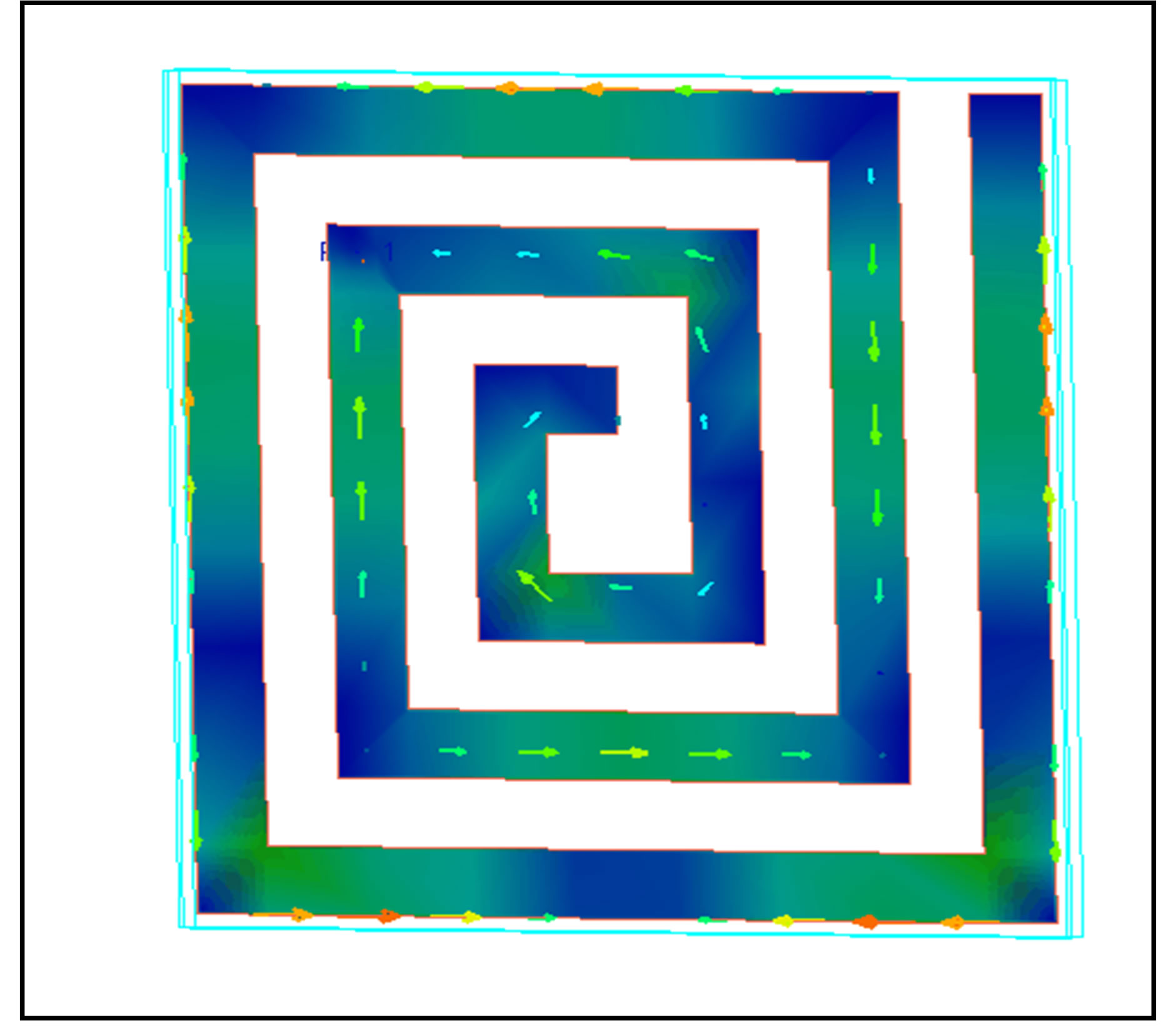
Figure 7. Meandering of the surface current on the radiating in spiral patch.
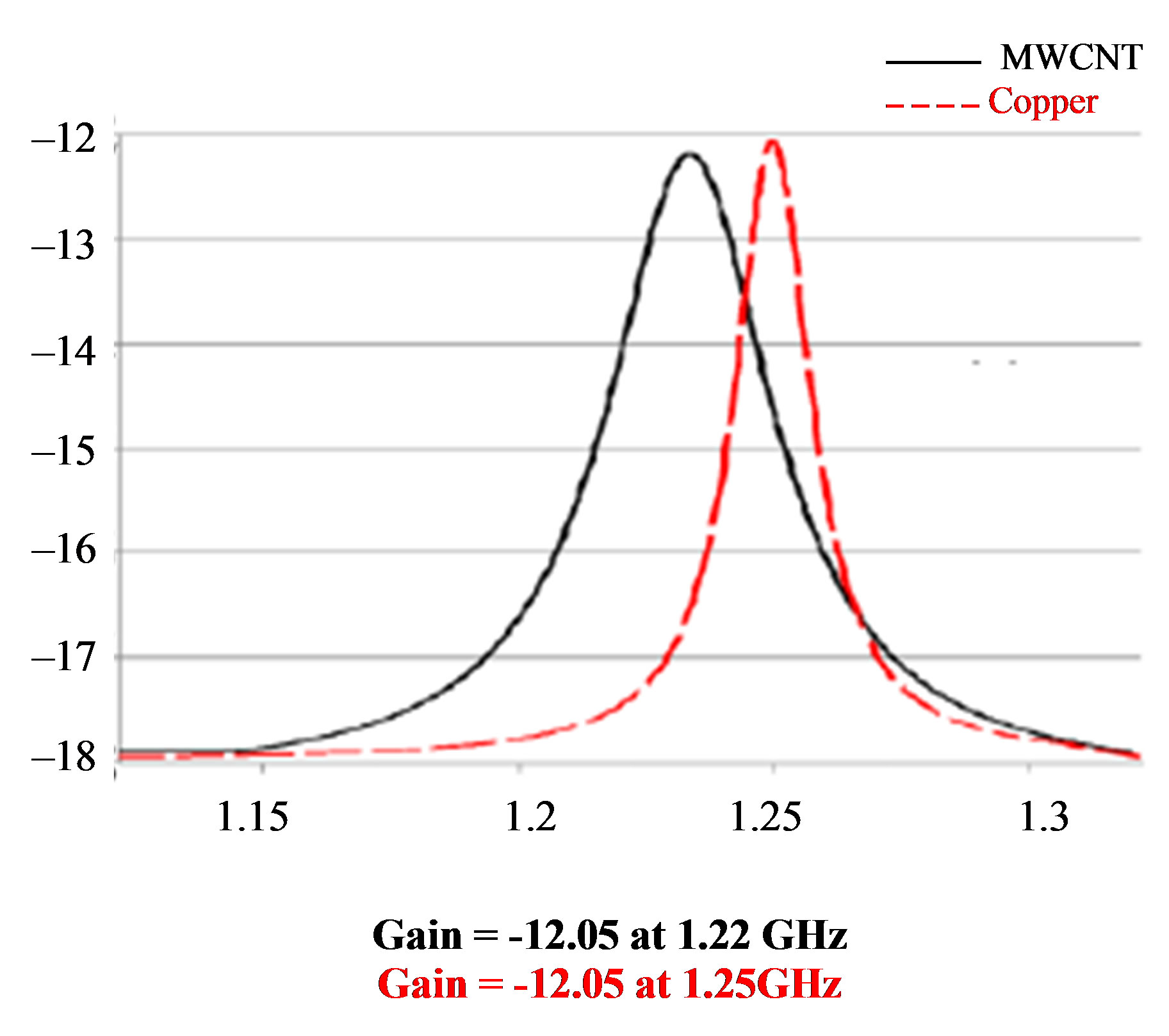
Figure 8. Antenna gain of MWCNT and copper spiral antenna simulated by CST MWS.
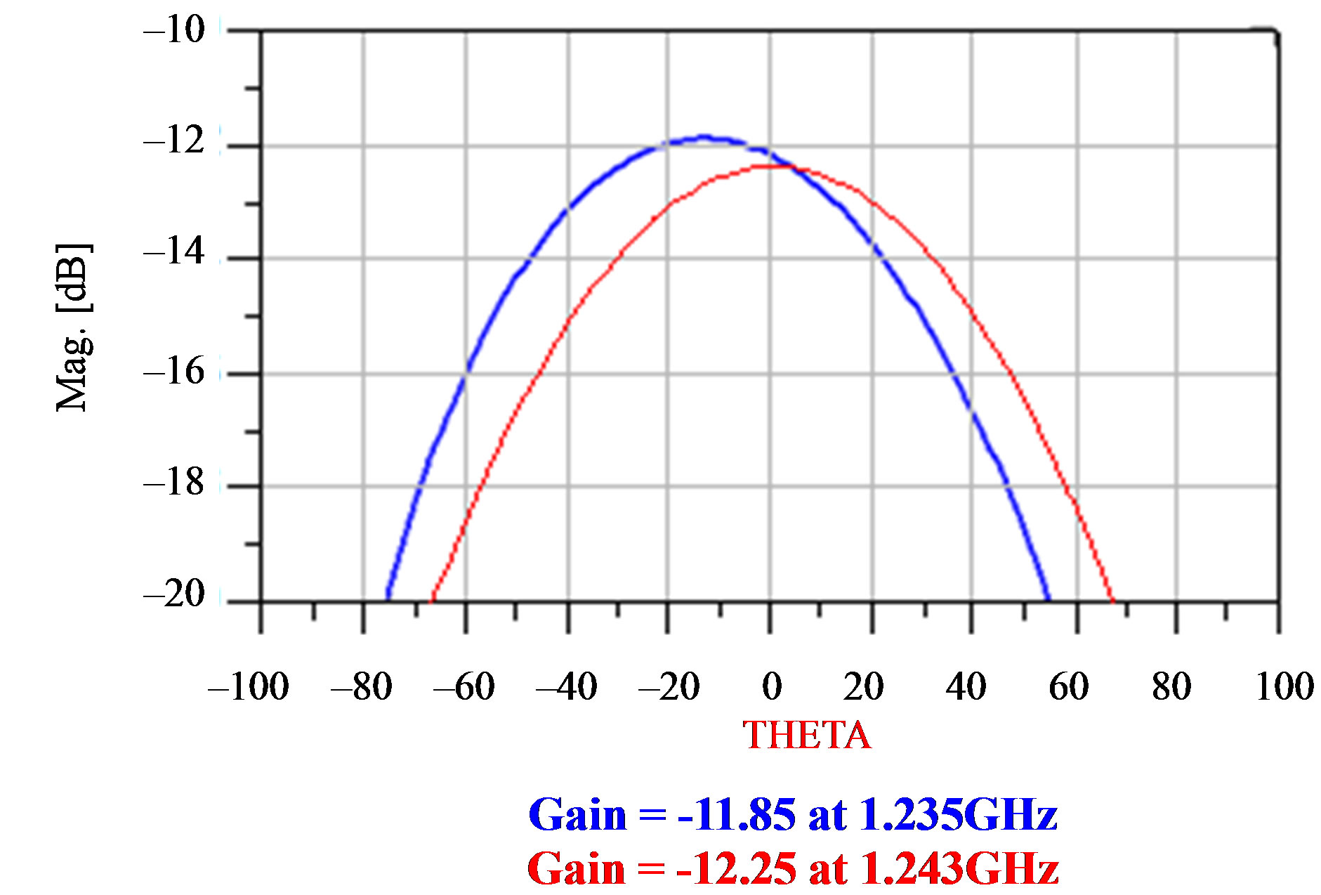
Figure 9. Antenna gain of MWCNT and copper spiral antenna simulated by ADS.

Figure 10. Antenna gain of MWCNT and copper spiral antenna simulated by CST MWS.
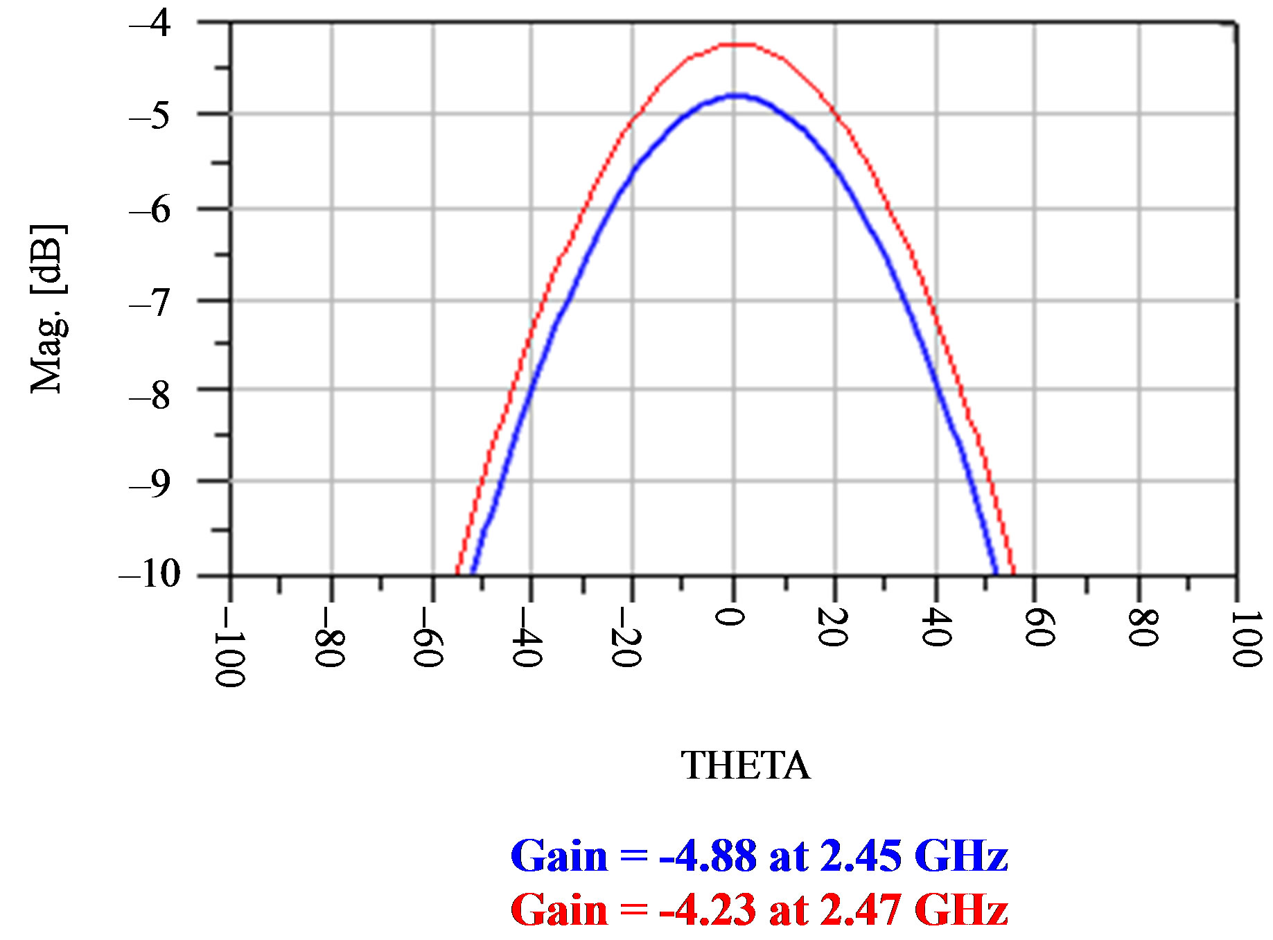
Figure 11. Antenna gain of MWCNT and copper spiral antenna simulated by ADS.
4. Concolusions
Adual-frequancy spiral microstrip antenna based on MWCNT ink has been simulated using ADS simulator, and compared with one obtained by others [1] using CST MWS simulator.
MWCNT ink and copper have been compared using ADS by those obtained by CST MWS in details We show the meandering of the surface current on the radiating in spiral patch.
It should be noted that the ADS simulator is faster and more reliable than the CST MWS simulator.
We suggest for future work, the comparative study for dual-band patch antenna designed, simulated, and implemented by ADS using copper [6] with another one using MWCNT using the same ADS simulator.
REFERENCES
- T. A. Elwi, D. G. Rucker, H. M. Al-Rizzo, H. R. Khaleel, E. Dervishi and A. S. Biris, “A Dual-Frequency Wearable MWCNT Ink-Based Spiral Microstrip Antenna,” Nano Science and Technology Institute—Nanotechnology, Vol. 1, 2010, pp. 266-269.
- E. Dervishi, Z. Li, A. R. Biris, D. Lupu, S. Trigwell and A. S. Biris, “Morphology of Multi-Walled Carbon Nanotubes Affected by the Thermal Stability of the Catalyst System,” Chemistry of Materials, Vol. 19, No. 2, 2007, pp. 179-184. doi:10.1021/cm062237l
- Z. Li, H. Kandel, E. Dervishi, V. Saini and A. Biris, “Does the Wall Number of Carbon Nanotubes Matter as Conductive Transparent Material?” Applied Physics Letter, Vol. 91, No. 5, 2007, pp. 12-20. doi:10.1063/1.2767215
- CST MICROWAVE STUDIO® (CST MWS) Is a Specialist Tool for the 3D EM Simulation of High Frequency Components. http://www.cst.com/
- Advanced Design System, 2008 Momentum Software Manual, Agilent Technologies, Palo Alto, 2008.
- M. Ali Soliman, W. Swelam, A. Gomaa and T. E. Taha, “Compact Dual-Band Microstrip Patch Array Antenna for MIMO 4G Communication Systems,” Proceedings of the 2010 IEEE Antennas & Propagation Symposium, Toronto, 11-17 July 2010, pp. 1-4.
- M. A. Soliman, W. Swelam, A. Gomaa and T. E. Taha, “Compact Dual-Band Microstrip Patch Array Antenna for MIMO 4G LTE and WLAN Systems,” Proceedings of 7th International Conference on Electric Engineering, pp. EE193-1-EE193-13.