Journal of Electromagnetic Analysis and Applications
Vol. 2 No. 8 (2010) , Article ID: 2594 , 8 pages DOI:10.4236/jemaa.2010.28065
Focal Region Field of a Two Dimensional Gregorian System Coated with Isotropic Chiral Medium
![]()
Faculty of Electronic Engineering, GIK Institute of Engineering Sciences and Technology, Topi, Swabi, N.W.F.P., Pakistan.
Email: rahim372@gmail.com, junaid@giki.edu.pk, mazhar_hussnain@yahoo.com
Received March 3rd, 2010; revised May 5th, 2010; accepted May 10th, 2010.
Keywords: Chiral medium, Maslov,smethod, Gregorian system, focal region field
ABSTRACT
Focal region field of a two dimensional Gregorian system coated with chiral medium is analyzed at high frequency. Maslov's method is used because the Geometrical Optics approximation fails at focal points. Maslov’s method combines the simplicity of ray theory and the generality of Fourier transform. Fields patterns are calculated numerically and the results are plotted. The effects of thickness of chiral layer, chirality parameter of the chiral medium and permittivity of the medium are analyzed. The problem of simple dielectric layer is discussed as a special case of this problem.
1. Introduction
The knowledge of focal region field of focusing systems is useful for synthesizing feed arrays in imaging and design of multiple beam antennas in communication systems. The focusing of electromagnetic waves into material media is also a subject of considerable current interest due to applications in hyperthermia, microscopy, and optical data storage. Geometrical optics (GO) approximation is one of the well known method for evaluating high frequency field. It has been widely used to study various kinds of problems in different areas of electromagnetics, acoustics and seismology [1-3]. GO approximation for wave solution is important in electromagnetics because it provide insight into the behavior of wave front. GO is used only for high frequency approximation of a wave, provided the ray tube does not vanish. However, at caustic regions the ray tube shrinks to zero and GO show singularity at these regions. These regions are of great importance in all practical problems e.g. parabolic, paraboloidal and circular reflectors etc. To avoid these singularities Maslov proposed a method based on Maslov`s theory [4,5]. Maslov’s method has been used to find the field at caustic regions [6-20]. The idea in Maslov's method provides a systematic procedure for predicting the field in the caustic region by combining the simplicity of ray theory and generality of the transform method. High frequency field expressions has been derived around feed point of a two dimensional Gregorian system using the Maslov’s method in [19]. The same focussing system has been coated with isotropic and homogeneous chiral medium and field expressions are obtained. In Section 2 the plane wave reflection from a chiral slab backed by perfect electric conducting (PEC) plane is considered. In Section 3 high frequency expression for the field of a chiral coated Gregorian system excited by plane wave is derived. Numerical results and discussion are presented in Section 4 and the paper is concluded in Section 5.
2. Reflection of Plane Waves From a Chiral Slab Backed by Conductor
In this paper we want to find the reflected field around the focal region of a two dimensional Gregorian’s main parabolic reflector coated with chiral medium. To achieve this the reflection of plane waves from a chiral slab backed by perfect electric conducting (PEC) plane is discussed as in [15,21]. As shown in figure 1 the region  is occupied by free space defined by following equations

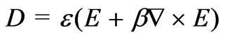
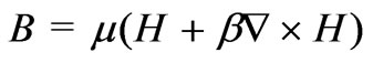
and the region  is occupied by the chiral medium defined by Drude-Born-Fadorov (DBF) constitutive relations [21] as follows
The PEC is placed at  as shown in figure 1. The reflection coefficients for the parallel and perpendicular components of polarization is calculated in [11]
 (1)
(1)
In the above equation,  ,
,  and
and ,
,  are the parallel and perpendicular components of polarization of the incident and reflected fields respectively.
  and
and  are
are  matrices. Elements of the matrices, which are Fresnel coefficients, are given in [15].
  and
and  are also
  matrices and are given in [15]. Using these reflection coefficients, the focal region fields of a two dimensional Gregorian's system are derived.
3. Focal Region Field of Two Dimensional Gregorian Reflector
Gregorian system consists of two reflectors, one is parabolic main reflector and another is hyperbolic sub-reflector as shown in figure 2. This system has several advantages over a single parabolic reflector.In this paper we want to study the caustic region field of a two dimensional Gregorian system when the main reflector is coated with chiral medium using GO and Maslov’s method. The equations of each reflector are given as follows
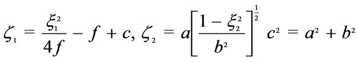
 (2)
(2)
In the above relations  and
and  are the Cartesian coordinates of the point on the parabolic and elliptical reflectors, respectively. The Incident wave traveling along the negative
  -axis is given by
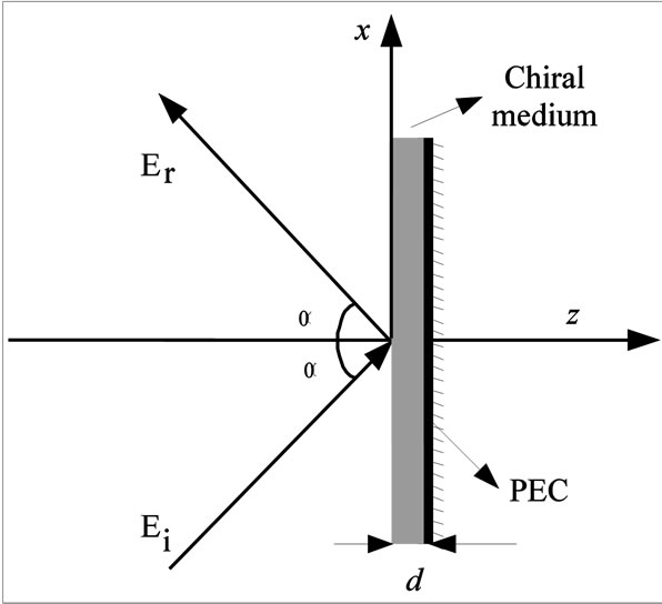
Figure 1. Reflection from a chiral slab backed by PEC
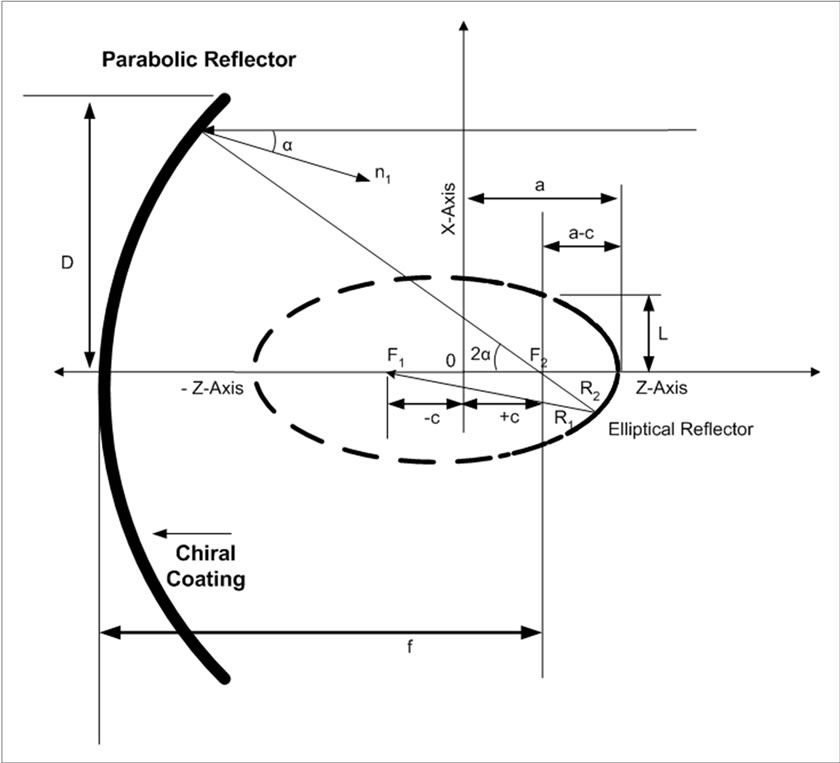
Figure 2. Gregorian antenna coated with chiral medium
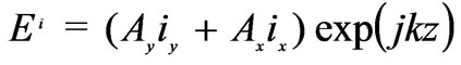 (3)
(3)
where,  ,
,  are the components along
  -axis and
  -axis of the initial amplitude of the incident field respectively. The wave reflected from the hyperboloidal surface is given by
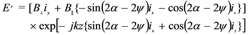 (4)
(4)
The wave vector of the wave reflected by the parabolic reflector is given by
 (5)
(5)
and the wave vector of the wave reflected by the hyperbolic reflector is
 (6)
(6)
where, the angle  and angle
  are given by the relation

In the above equations  and
and  are the distances from the point
  to the focal points
  and
and , respectively. The unit normal vectors to the parabolic and hyperbolic surfaces are given by
  and
and  respectively. These normals can be written as

The general form of the geometrical optics solution for the wave is given by [19]
 (7)
(7)
The Jacobian associated with the wave reflected by the parabolic reflector is given by [19]
 (8)
(8)
The Cartesian coordinates of the ray reflected by the hyperbolic surface is given by
 (9)
(9)
 (10)
(10)
where, . In the above equation
  and
and  are the rectangular components of reflected wave vectors
  and
and , respectively. Now we consider the field after the reflection from the hyperbolic cylinder. The transformation from the Cartesian coordinates
  to the ray coordinates
  is given by [19]
 (11)
(11)
Thus the geometrical ray expression of each component of the reflected wave is
 (12)
(12)
 (13)
(13)
 (14)
(14)
where,  is the amplitude of the incident wave at the reflection point on the parabolic surface and
 (15)
(15)
 (16)
(16)
 (17)
(17)
As indicated by (7),  will become infinite for
  i.e. at the caustic points. The expression which is valid at the focal point according to Maslov’s method is given by [19]
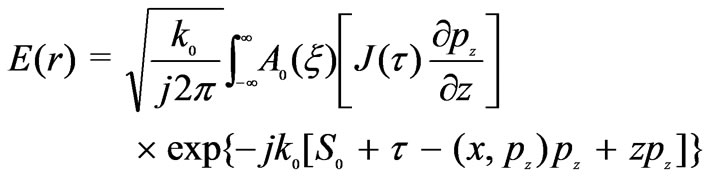 (18)
(18)
The amplitude term  in the above equation is given by [19]
 (19)
(19)
The phase function is given by
 (20)
(20)
where,  is given by (15). The extra term is given by


We substitute (19)-(20) into (18) and taking , we can find the finite field around the caustic as given below
 (21)
(21)
 (22)
(22)
 (23)
(23)
In the above equation,  ,
,  ,
,  and
and  are expressed in terms of
  and
and  and
and  are the subtention angles
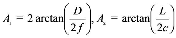
  at the edges of the parabolic and hyperbolic surfaces. The limit of integration are calculated by the expression
4. Result and Discussion
Field pattern around the caustic region of a Gregorian system are determined using (21-23) by performing the integration numerically. The line plots of the field around the focal region located between the two reflectors, that point  in figure 2. Simulation were done for
 ,
,  ,
,  ,
,  ,
,  and different values of
 ,
,  , and
, and . We have considered two types of polarization for incident wave. One is
 ,
,  and the other is
 ,
, . The results are plotted in Figures 3-20. In all figures horizontal axis is
  -axis and vertical axis corresponds to the absolute value of reflected field component. All plots are taken at
 . We have studied the effects of thickness of the the coated layer (
 ), the chirality parameter (
 ) and the relative permittivity of the me-
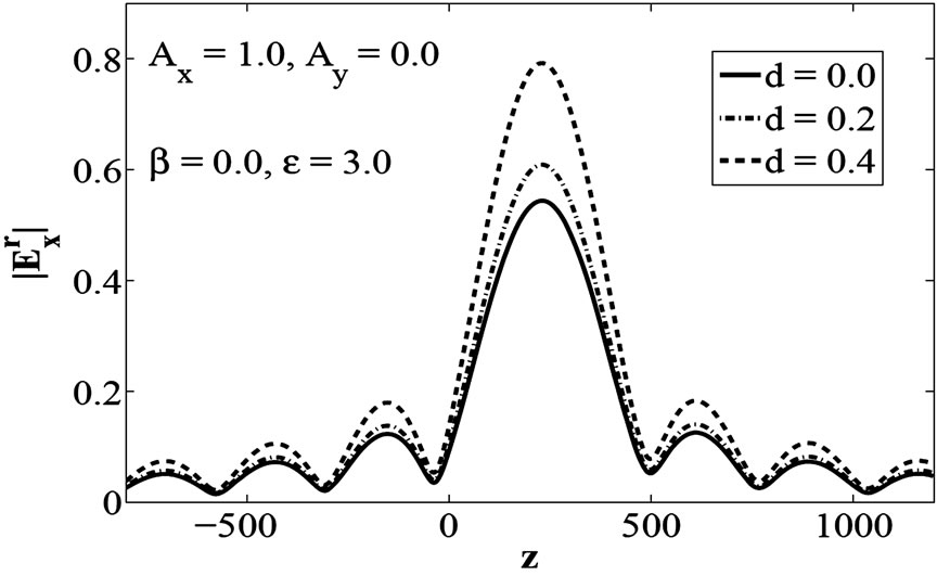
Figure 3. Plot of , when parabolic reflector is coated with dielectric layer of varying thickness d
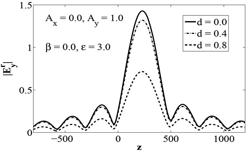
Figure 4. Plot of , when parabolic reflector is coated with dielectric layer of varying thickness d
dium ( ) on the focal region field. Figures 3-5 show the effect of increase in the value of
  keeping
  and
and , that is ordinary dielectric case. We have shown in figure 3 and 5the
  and
and  for
for . These figures show that increase in thickness of the coated layer (
 ) results an increase in
  and
and . Figure 4 shows the plot of
  for
for . This figure shows decrease in field strength as
  increases. Figures 6-11 show the effect of
  while keeping
  and
and  for both types of polarization. Figures 7 and 11 show increase in the field strength of
  and
and  for
for , respectively. Figure 6 and 10 show the cross polarization effect due to chiral medium for polarization
 , which also increases with increase in
 . For
. For , cross polarization effect vanishes and field strength increases with increase in
 . Figure 8 shows the plot of
  for
for , which decreases with increase in
 , and Figure 9
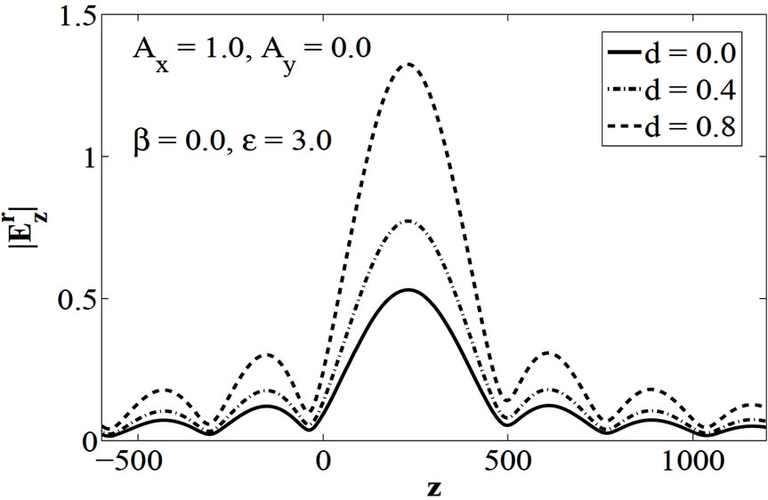
Figure 5. Plot of , when parabolic reflector is coated with dielectric layer of varying thickness d
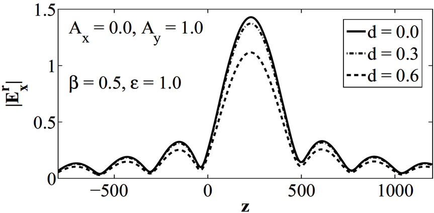
Figure 6. Plot of , when the thickness of the coated layer d is varying. The impedance of chiral medium is equal to that of free space
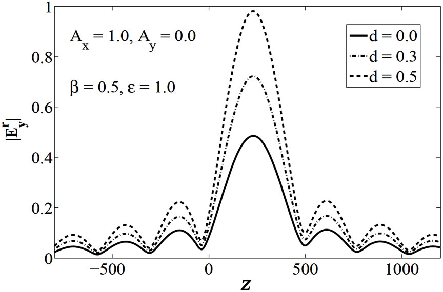
Figure 7. Plot of , when the thickness of the coated layer d is varying. The impedance of chiral medium is equal to that of free space

Figure 8. Plot of , when the thickness of the coated layer d is varying. The impedance of chiral medium is equal to that of free space
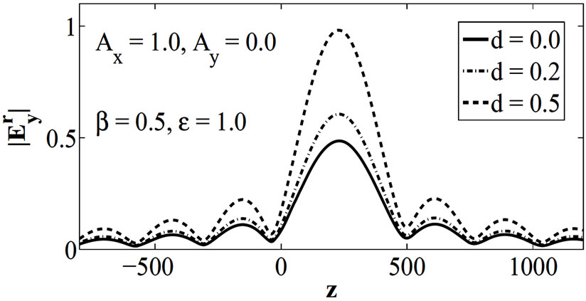
Figure 9. Plot of , when the thickness of the coated layer d is varying. The impedance of chiral medium is equal to that of free space
shows the plot for . This figure shows that cross polarization effect are zero for
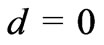 , but increases with increase in layer thickness
 .
.
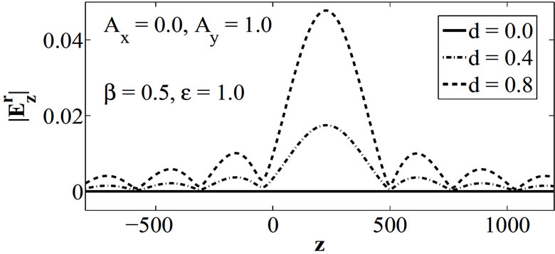
Figure 10. Plot of , when the thickness of the coated layer d is varying. The impedance of chiral medium is equal to that of free space

Figure 11. Plot of , when the thickness of the coated layer d is varying. The impedance of chiral medium is equal to that of free space

Figure 12. Plot of  showing the effect of chirality parameter
 . The impedance of chiral medium is equal to that of free space

Figure 13. Plot of  showing the effect of chirality parameter
 . The impedance of chiral medium is equal to that of free space

Figure 14. Plot of  showing the effect of chirality parameter
 . The impedance of chiral medium is equal to that of free space
Figure 15. Plot of  showing the effect of relative permittivity
  of dielectric layer
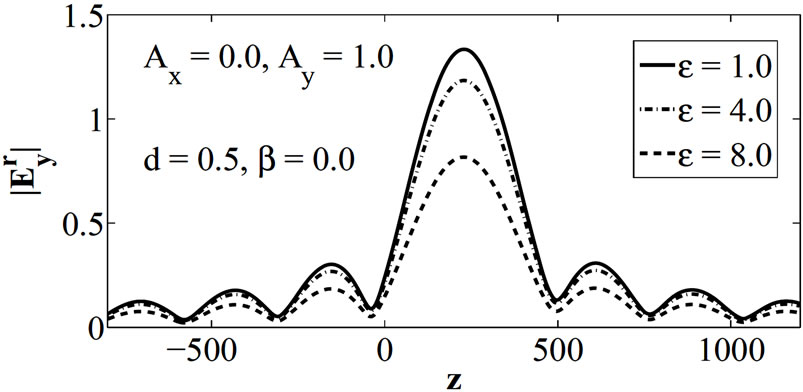
Figure 16. Plot of  showing the effect of relative permittivity
  of dielectric layer
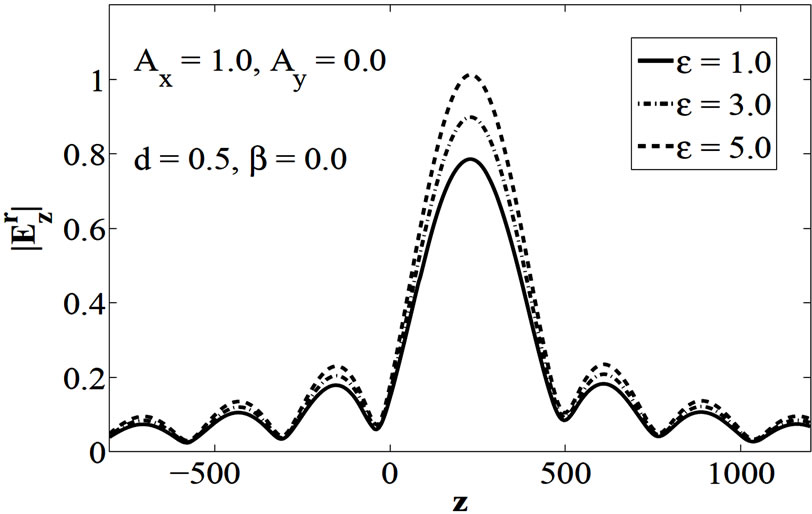
Figure 17. Plot of  showing the effect of relative permittivity
  of dielectric layer

Figure 18. Plot of  showing the effect of relative permittivity
  of chiral layer
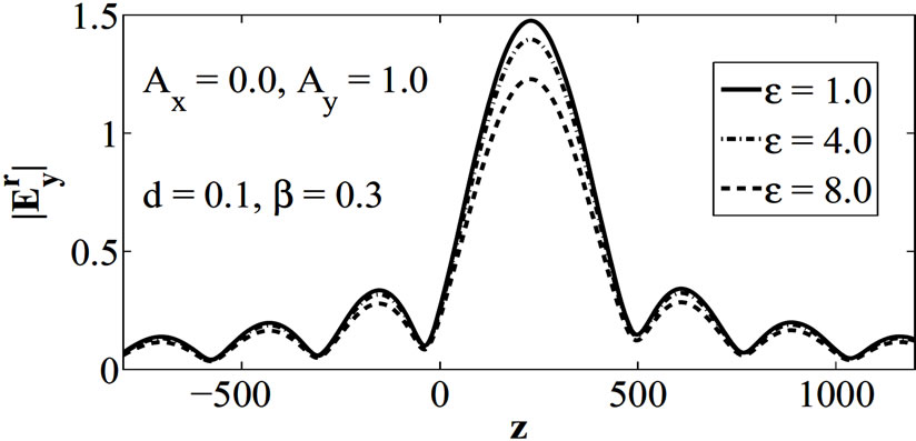
Figure 19. Plot of  showing the effect of relative permittivity
  of chiral layer
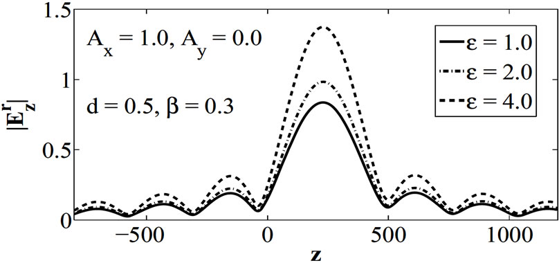
Figure 20. Plot of  showing the effect of relative permittivity
  of chiral layer
Figures 12 and 14 show the effect of chirality parameter  on field components while keeping
  and
and . Figures 12 and 14 show the plots of
  and
and  for
for  respectively. These figures show that field strength increases with increase in chirality parameter
 . Figure 13 shows that
  decreases with increase in
 . Cross polarization effects have not been shown because they have same trends as discussed above. Figures 15-17 show the effect of
  while keeping
  and
and , that is for ordinary dielectric case. Figures 15 and 17 show the plot of
  and
and  for polarization
  respectively and show the increase in the field strength if we increase the relative permittivity of dielectric medium coated on the surface of reflector. Figure 16 shows that
  decreases with increase in
  for polarization
 . Figures 18-20, which are for chiral coating, show the same trends as in Figures 15-17.
5. Conclusions
Focal region fields of a two dimensional Gregorian reflector is analyzed using GO and Maslov’s method. Two types of polarization are discussed. The reflected field components are analyzed numerically and the results are given in the focal plane. It is concluded that increase in chirality parameter ( ), increase in thickness (
 ) and relative permittivity (
 ), results in increase in of
  and
and  for
for . While
  decreases for
 . Cross polarized fields exist when
  and increase with increase in value of
 .
.
REFERENCES
- Y. A. Kravtsov and Y. I. Orlov, “Caustics, Catastrophes, and Wave Fields,” Springer Verlag, Berlin, 1993.
- G. A. Dechamps, “Ray Techniques in Electromagnetics,” Proceedings of IEEE, 1972, pp. 1022-1035.
- C. H. Chapman and R. Drummond, “Body Wave Seismograms in Inhomogeneous Media Using Maslov Asymptotic Theory,” Bulletin of the Seismological Society of America, Vol. 72, No. 68, 1982, pp. 277-317.
- V. P. Maslov, “Perturbation Theory and Asymptotic Methods,” Moskov., Gos., University, Moscow, 1965 (in Russian). (Translated into Japanese by Ouchi et al., Iwanami).
- V. P. Maslov and V. E. Nazaikinski, “Asymptotic of Operator and Pseudo-Differential Equations,” Consultants Bureau, New York, 1988.
- A. Ghaffar, Q. A. Naqvi and K. Hongo, “Analysis of the Fields in Three Dimensional Cassegrain System,” Progress in Electromagnetics Research, Vol. 72, 2007, pp. 215-240.
- A. Hussain, Q. A. Naqvi and K. Hongo, “Radiation ChaRacteristics of the Wood Lens Using Maslov’s Method,” Progress in Electromagnetics Research, Vol. 73, 2007, pp. 107-129.
- Y. Ji and K. Hongo, “Analysis of Electromagnetic Waves Refracted by a Spherical Dielectric Interface Method,” Journal of the Optical Society of America, Vol. 8, No. 3, 1991, pp. 541-548.
- Y. Ji and K. Hongo, “Field in the Focal Region of a Dielec-Tric Spherical by Maslov's Method,” Optical Society of America. Vol. 8, No. 11, 1991. pp. 1721-1728.
- K. Hongo, Y. Ji and E. Nakajima, “High Frequency Expression for the Field in the Caustic Region of a Reflector Using Maslov’s Method,” Radio Science, Vol. 21, No. 6, 1986, pp. 911- 919.
- K. Hongo and Y. Ji, “High Frequency Expression for the Field in the Caustic Region of a Cylindrical Reflector Using Maslov’s Method,” Radio Science, Vol. 22, No. 3, 1987, pp. 357-366,.
- K. Hongo and Y. Ji, “Study of the Field Around the Focal Region of Spherical Reflector Antenna by Maslov’s MetHod,” IEEE Transaction Antennas Propagat, Vol. 36, No. 5, 1988, pp. 592-598.
- R. W. Ziolkowski and G. A. Deschamps, “Asymptotic Evaluation of High Frequency Field near a Caustic: An IntrOduction to Maslov’s Method,” Radio Science, Vol. 19, No. 4, 1984, pp. 1001-1025.
- M. Faryad and Q. A. Naqvi, “High Frequency Expression for the Field in the Caustic Region of Cylindrical Reflector Placed in Chiral Medium,” Progress in Electromagnetics Research, Vol. 76, 2007, pp. 153-182.
- Faryad, M. and Q. A Naqvi, “High Frequency Expression for the Field in the Caustic Region of a Parabolic Reflector Coated with Isotropic Chiral Medium,” Journal of Electromagnetic Waves and Application, Vol. 22, 2008, pp. 965-986.
- M. Faryad and Q. A. Naqvi, “Cylindrical Reflector in Chiral Medium Supporting Simultaneously Positive Phase Velocity and Negative Phase Velocity,” Journal of Electromagnetic Waves and Applications, Vol. 22, No. 2, 2008, pp. 563-572.
- A. Ghaffar, A. Hussain, Q. A. Naqvi and K. Hongo, “Radiation Characteristics of an Inhomogeneous Slab Using Maslov’s Method,” Journal of Electromagnetic Waves and Applications, Vol. 22, No. 2, 2008, pp. 301-312.
- A. Aziz, A. Ghaffar, Q. A. Naqvi and K. Hongo, “Analysis of the Fields in Two Dimensional Gregorian System,” Journal of Electromagnetic Waves and Applications, Vol. 22, no. 1, 2008, pp. 85-97.
- A. Aziz, Q. A. Naqvi and K. Hongo, “Analysis of the Fields in Two Dimensional Cassegrain System,” Progress in Electromagnetics Research, Vol. 71, 2007, pp. 227-241.
- A. Ghaffar, A. Rizvi and Q. A. Naqvi, “Field in the Focal Space of Symmetrical Hyperboloidal Focusing Lens,” Progress in Electromagnetics Research, Vol. 89, 2009, pp. 255-273.
- A. Lakhtakia, “Beltrami Fields in Chiral Media,” World Scientific Series in Contemporary Chemical Physics, 1994.
- S. Bassiri, “Electromagnetic Waves in Chiral Media,” Recent Advances in Electromagnetic Theory, H. N. Kritikos and D. L. Jaggard, Eds., Springer-Verlag, New York, 1990.
- V. Tuz and V. Kazanskiy, “Periodicity Defect Influence on the Electromagnetic Properties of a Sequence with Bi-Isotropic Layers,” Progress in Electromagnetics Research B, Vol. 7, 2008, pp. 299-307.