Journal of Electromagnetic Analysis and Applications
Vol. 1 No. 3 (2009) , Article ID: 727 , 11 pages DOI:10.4236/jemaa.2009.13026
Islanding Detection Method for Multi-Inverter Distributed Generation
Institut de recherche sur l'hydrogène (IRH), Département de Génie Électrique et Génie Informatique, Université du Québec à Trois-Rivières, Trois-Rivières (Québec), Canada.
Email: {Alben.cardenasgonzalez, Kodjo.agbossou}@uqtr.ca.
Received May 21st, 2009; revised July 23rd, 2009; accepted August 23rd, 2009.
Keywords: Distributed Generation (DG), Interconnected Power Systems, Islanding Detection, Power Generation, Voltage Positive Feedback.
ABSTRACT
Islanding detection is an essential function for safety and reliability in grid-connected distributed generation (DG) systems. Several methods for islanding detection are proposed, but most of them may fail under multi-source configurations, or they may produce important power quality degradation which gets worse with increasing DG penetration. This paper presents an active islanding detection algorithm for Voltage Source Inverter (VSI) based multi-source DG systems. The proposed method is based on the Voltage Positive Feedback (VPF) theory to generate a limited active power perturbation. Theoretical analyses were performed and simulations by MATLAB/ Simulink /SimPowerSystems were used to evaluate the algorithm’s performance and its advantages concerning the time response and the effects on power quality, which turned out to be negligible. The algorithm performance was tested under critical conditions: load with unity power factor, load with high quality factor, and load matching DER’s powers.
1. Introduction
The Distributed Energy Resources (DER) including Distributed Generation (DG) and Distributed Storage (DS) are, as renewable energy resources, very important to improve power distribution reliability and capability. Their penetration is increasing nowadays and their utilization shows potential for rural utility solutions [1]. The Hydrogen Research Institute (HRI) has designed and developed a renewable energy (RE) system which includes Photovoltaic (PV) arrays, Fuel Cells (FC) and Wind Turbine Generators (WTG) with an energy storage capability using electrolytic hydrogen [2]. This RE system operates presently in stand-alone mode. It can be adapted for rural dispersed generation solutions and interconnected with the electric utility grid by using inverter based interfaces (DC/AC static converter). Figure 1(a) is a simplified diagram of the basic RE unit as implemented at HRI. Figure 1(b) shows the possible multisource DER system presently under construction.
An important technical issue with utility interfaced DER systems is unintentional islanding operation. The islanding condition occurs when the utility is disconnected and the DG continues to supply power to the local load. This condition is not desirable because it can generate voltage and frequency instability and power quality degradation; and it constitutes a great risk for maintenance personnel. In view of the importance of human and equipment protection, unintentional islanding for DG operation is not tolerated [3]. For these reasons the detection of unintentional islanding operation is required as rapidly as possible to allow the timely disconnection of the DG units. According to the IEEE 1547-2003 standard [4], the DG disconnection is required within two seconds after the utility disconnection. Consequently, for safety DER integration, Anti-Islanding (AI) protection is a requirement.
Remote and local techniques are used for islanding detection. Remote techniques such as Supervisory Control and Data Acquisition (SCADA), Trip (disconnect) Signal and Power Line Carrier Communication (PLCC) systems are centralized methods implemented on the utility side. They offer high performance and applicability on multisource topologies. However, those centralized methods are expensive to implant [5]. On the other hand, local techniques include passive and active methods which are implemented on the DG side. Local passive methods have a large Non Detection Zone (NDZ), and hence are not useful for high DG penetration. A solution for the NDZ reduction is the utilisation of local active anti-islanding methods.
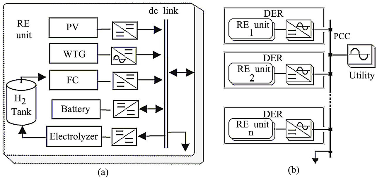
Figure 1. Simplified diagram of stand-alone RE system implemented at HRI and the possible multi-source DER system
Those active methods are currently based on the injection of voltage, frequency or output power perturbations, and the subsequent monitoring for the detection of changes in electric parameters to confirm islanding condition. Those methods can detect the islanding condition, but one of their problems is that they can fail when multiple sources are connected at PCC, because the effect produced by one source may be interfered by another one if synchronization between the multiple converters is not possible. Another drawback of active methods is that they can cause power quality disturbances as Total Voltage Harmonic Distortion (TVHD) increase and voltage and frequency fluctuations or instability. These problems become bigger if the introduced perturbation is increased to make possible the islanding detection [6,7], especially in systems with high penetration.
Use of the Correlation Function combined with active methods is proposed in [8,9] and [10] for multi-source topologies. In [8], the correlation function is combined with an active method that introduces a constant alternating perturbation of reactive power (±5% and ±10%), the anti-islanding algorithm is implanted in only one (master unit) of multiple DGs, and the others units use a passive anti-islanding scheme. The detection time depends on the output power of the master unit and on the reactive power perturbation level. In [9] and [10], the correlation function is combined with an active algorithm that introduces a user defined or random (M-sequence) perturbation of the output voltage (fixed to ±2V for 120V/60Hz system). The correlation function may change with the number of connected DGs, and consequently a threshold adjustment is necessary if the number of units change.
In this article we propose an active islanding detection method based on Voltage Positive Feedback (VPF) and passive method Under/Over Voltage Protection and Under/Over Frequency Protection (U/OVP-U/OFP). The proposed method can be used on multi-source configurations, and allows both unity power factor and power factor improvement operation modes. This method introduces a limited active power perturbation proportional to measured variations of PCC voltage (VPCC). Simulations using MATLAB™/Simulink™ and SimPowerSystems ™ are carried out to validate the algorithm under several operating conditions.
2. Power Control Scheme
The system we consider is illustrated in Figure 1, where several DG units are interconnected with the utility at PCC. Each unit has an IGBT voltage source inverter (VSI) and its active and reactive power control using a current control scheme [11] as shown by Figure 2.
In this power control scheme, the output current fundamental magnitude (IINV(1)) and phase angle (fI) are calculated respectively using (1) and (2).
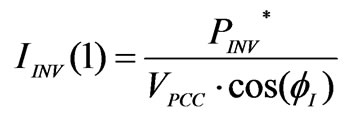 (1)
(1)
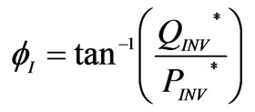 (2)
(2)
where, PINV* and QINV* are respectively the reactive and active power external set points for the DG unit.
The power angle fI represents the phase angle between the inverter output fundamental current and the fundamental voltage measured at PCC.
The resultant set-point current (3) is used to generate the switching signals for the IGBT bridge inverter, using Hysteresis Current Control (HCC) or Sinusoidal Pulse Width Modulation (SPWM) techniques.
 (3)
(3)
where q and f are the phase angle and frequency of the voltage measured at PCC, and t is time in seconds.
Considering that the proposed algorithm (see Section 3)
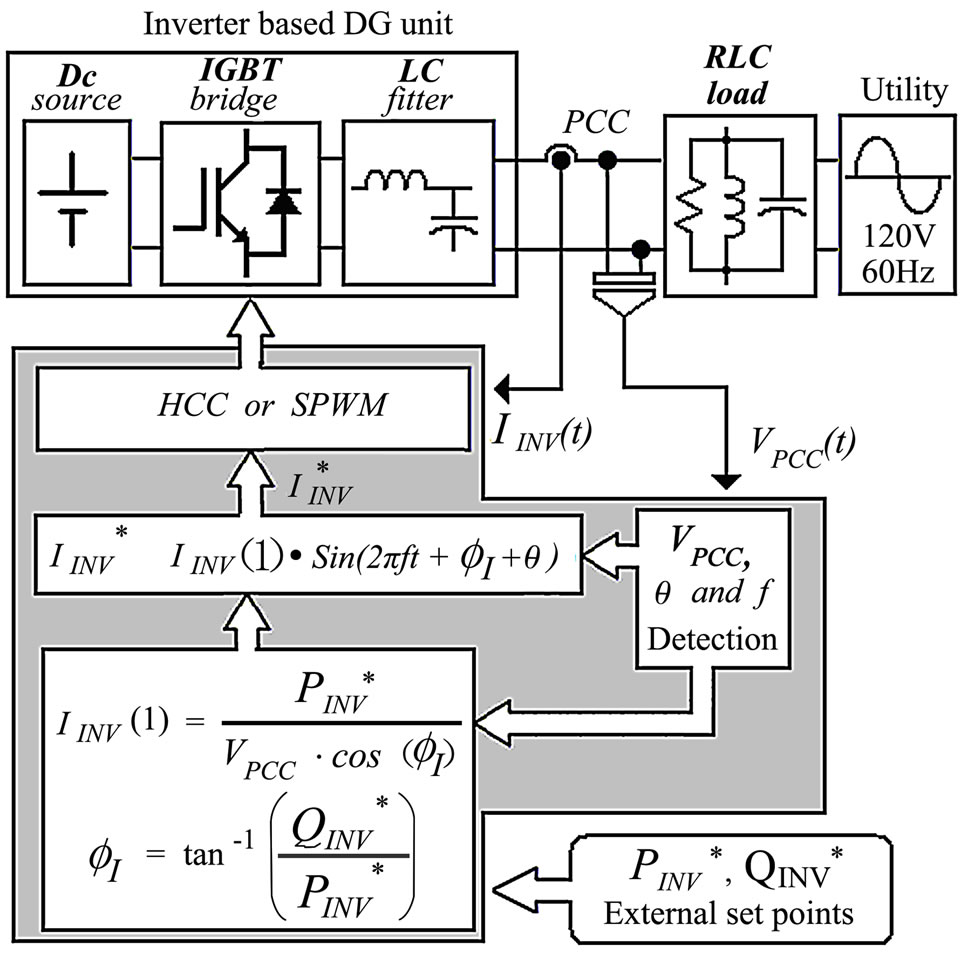
Figure 2. Power control scheme for single grid connected DG unit
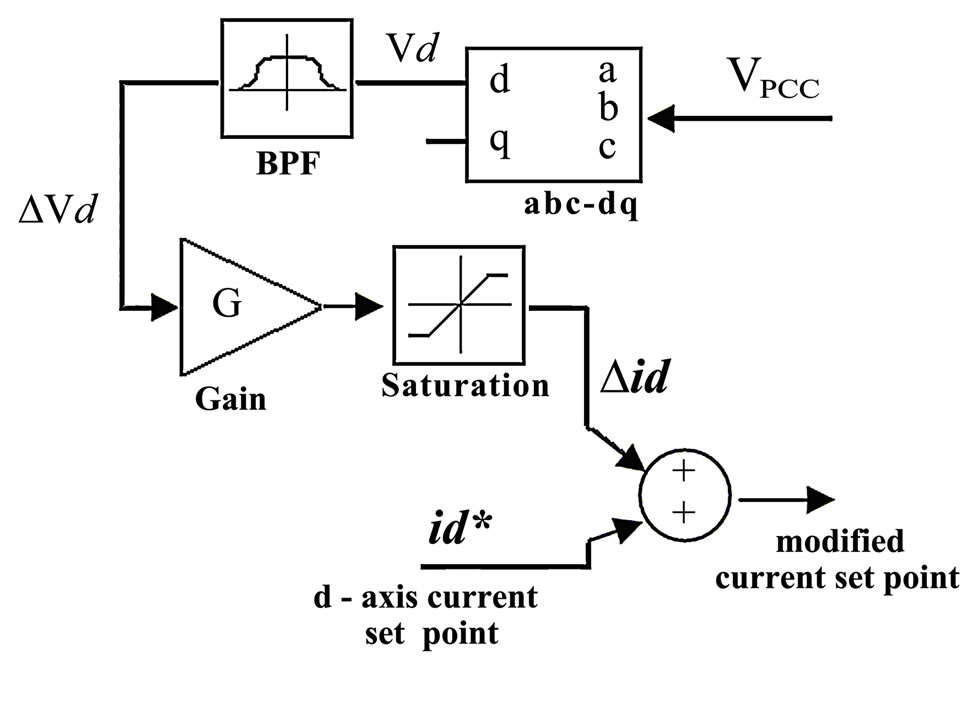
Figure 3. Voltage positive feedback with d-q current control scheme
introduces an active power perturbation that is added to the external set point, we are not limited to the Figure 2 power control scheme, and it may be changed to another one such as the d-q transformation based power control scheme [3]. Notice that the d-q control scheme is convenient when decoupled active and reactive power control is required principally in three phase systems.
3. Islanding Detection Algorithm
This section describes the voltage positive feedback principle and the proposed active islanding detection algorithm.
3.1 Voltage Positive Feedback Islanding Detection Methods
Positive feedback with d-q current control based family of islanding detection methods is presented in [12] and [13]. These methods consider the relation between the active (P) and reactive (Q) powers with the voltage magnitude (V) and frequency (f) as shown in (4) and (5), and the effects of current magnitude and angle deviation on the output active and reactive powers.
 (4)
(4)
 (5)
(5)
where, w=2pf, and R, C and L are the resistance, capacitance and inductance of the resonant load.
This family of islanding detection methods includes frequency and magnitude of voltage positive feedback based schemes. The positive feedback is used to generate a low frequency perturbation signal (∆id or ∆iq) that is added to the id* and/or iq* set points.
Figure 3 shows the principle of Voltage Positive Feedback (VPF) with d-q current control scheme. The d-axis component of VPCC (Vd) is monitored and filtered using a band pass filter (BPF) to obtain the voltage variation ∆Vd, this voltage variation is amplified with a preset gain G (A/V) and used as d-axis current perturbation (∆id). The d-axis current perturbation signal affects directly the inverter output power and consequently the VPCC magnitude and frequency in islanded mode. A saturation block is used to limit the output current perturbation. As a result, on islanding condition a rising deviation of frequency (df) or magnitude (dV) of VPCC is observed, and this deviation can trip U/OVP or U/OFP for DG safety disconnection.
An important characteristic of the VPF based methods is the low power quality degradation in contrast with other active methods that use distorted signals injection, as proposed in [14] and [15].
On the other hand, the time necessary to generate the trip signal using the VPF based method is determined by the load quality factor qF (6) and the feedback preset gain G. One simple way to improve the response speed is to increase G, but this solution increases the risk of voltage or frequency instability, especially in multi-source topologies.
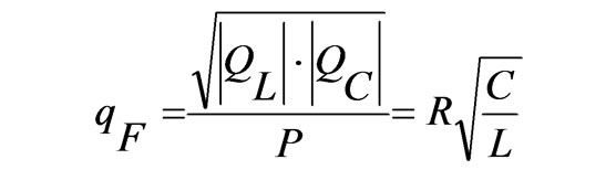 (6)
(6)
The Sandia Voltage Shift (SVS) method [6] uses the utility voltage to calculate the output current amplitude; in this method the average voltage of the utility is compared with the actual voltage in each electric cycle (orhalf cycle) to calculate the current perturbation that is amplified by a preset gain.
In both methods, SVS as well as VPF with d-q transformation, the output voltage at the islanding condition is forced to the trip points of the U/OV protection by an important output current reduction or increase, and it is finally the U/OVP that shuts down the power converter. This important perturbation of the output current before the disconnection may affect the load, and is not appropriate if stand-alone operation of the system is desired after the safety disconnection.
3.2 Proposed Voltage Positive Feedback Scheme
We propose to use the VPF concept, taking the RMS
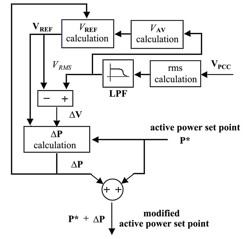
Figure 4. Proposed voltage positive feedback scheme
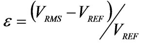
voltage measured at PCC (VRMS) as the feedback variable to generate a limited active power perturbation. The basics of the proposed scheme are presented in Figure 4. The VRMS (after the LPF filter) is compared with a reference voltage VREF, and the difference ∆V is used to calculate the active power perturbation ∆P.
The reference voltage VREF[k+1] is set initially equal to the nominal RMS voltage (VNOM), and is subsequently updated only on System Stable Condition (SSC) using the historic RMS average voltage VAV (7). Otherwise, the new voltage reference (VREF[k+1]) is set equal to the old reference value (VREF[k]) according to (8). The SSC is defined as the condition where both the power and the voltage perturbations (∆P and ∆V) are stable.
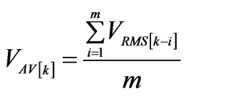 (7)
(7)
where, m is the number of samples considered for the average calculation.
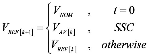 (8)
(8)
The active power perturbation ∆P is calculated using the maximal allowed power perturbation ∆PMAX, the minimal power perturbation ∆PMIN, a gain factor G, and the difference between VREF and VRMS, according to (9,10) and (11).
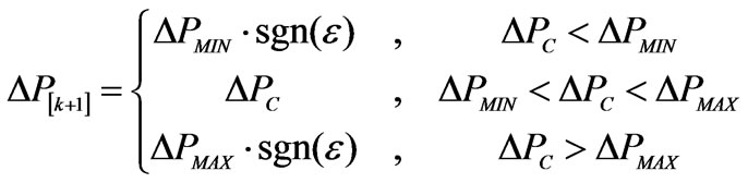 (9)
(9)
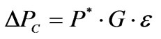 (10)
(10)
 (11)
(11)
3.3 Parameter Selection
The parameters ∆PMIN, ∆PMAX and G are selected to produce a low active power variation in the interconnected mode and a low voltage variation in the islanding detection period. Considering an ideal utility source, the voltage error in the interconnected operation mode may be close to zero, but in practice a minimal error is always resent, and this error affects the real output power. We set the ∆PMIN near the mean active power perturbation calculated using the typical utility voltage variations (εMIN). Based on the measured voltage of the utility, we take a εMIN=±0.167% (±0.2V at 120V) as the minimal voltage error. This εMIN allows us to set a minimal active power perturbation ∆PMIN=±0.5% using a gain of G=3. At the islanding condition, if the system operates at unity power factor, this ∆PMIN introduces a voltage variation of ±0.25% (±0.3V at 120V).
To limit the effects on the output voltage in the detection period, we set the ∆PMAX=±2.5% to produce a maximal voltage error ε=± 1.24% (±1.5V at 120V). This setting permits the islanding detection without output voltage degradation if the load and DG powers are close or matched.
3.4 Expected Operation of the Proposed Algorithm
In grid connected mode, the active power deviation is reduced to minimal ∆PMIN on voltage stability condition. The expected evolution of voltages (VREF and VRMS) and the active power perturbation for the islanded mode is
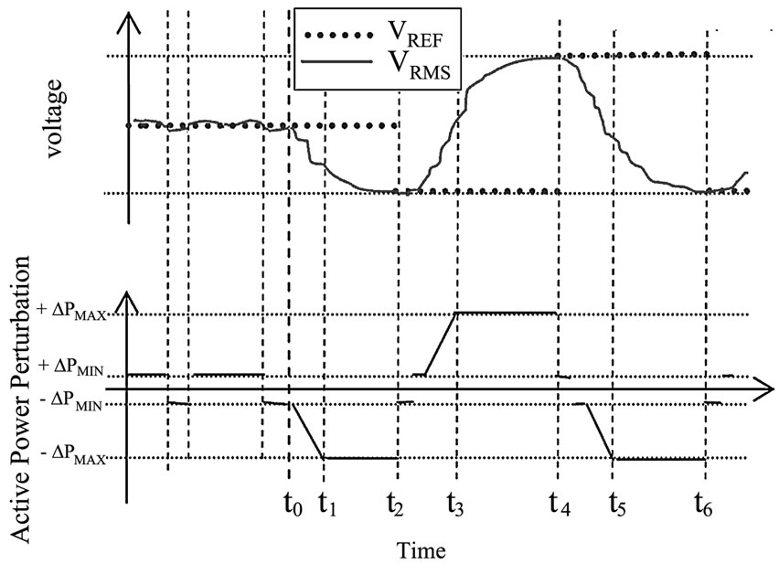
Figure 5. Expected effect of the proposed VPF scheme under islanding condition
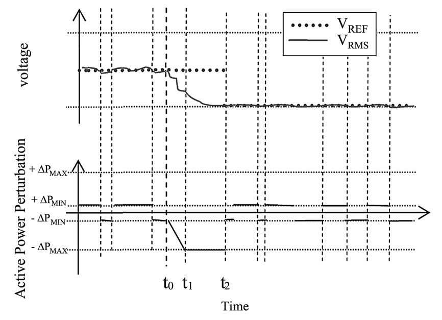
Figure 6. Expected effect of the proposed VPF scheme under voltage reduction and normal voltage variation
shown by Figure 5. Before the utility disconnection (t
The SSC condition is reached at t=t2 with voltage stabilization, and VREF is updated to VAV. Consequently, a reduction and a subsequently positive increase of ∆P are expected to produce a voltage level increase (from t2 to t4). The power perturbation is saturated at t=t3, and a new SSC is reached at t=t4. A cyclic power perturbation and a voltage level oscillation can be observed and used to confirm the islanding condition.
The expected trajectories for a voltage variation are presented in Figure 6. In this case, if an important voltage variation is occurred at t=t0, the VPF effect produces a negative increasing of ∆P until its saturation at t=t1. The SSC condition is reached with VRMS stabilization at t=t2. Consequently, the VREF is updated and the active power perturbation is reduced to ∆PMIN. Subsequently the minimal active power perturbation may be observed as an effect of the normal voltage variation.
3.5 Islanding Confirmation
If the average of the magnitude of the active power perturbation (∆PAV) is calculated and observed during a detection period TDET, then under islanding condition the expected profile of this variable is shown in Figure 7, and we can use this new variable to establish the islanding condition. For islanding condition confirmation, the ∆PAV is compared to two thresholds values ∆PAC (Active Counter) and ∆PRC (Reset Counter) to activate or to reset a time counter (TC). If the TC count is larger than a preset limit of time TMAX, the islanding condition can be confirmed.
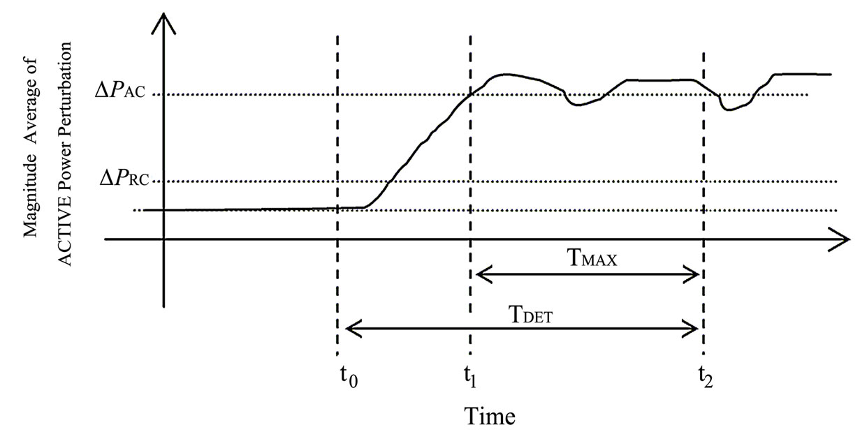
Figure 7. Expected magnitude average of the active power perturbation on islanding condition
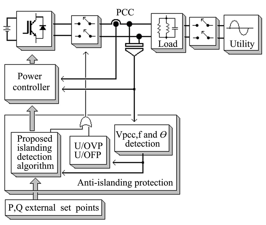
Figure 8. Simplified diagram of the proposed anti-islanding protection scheme
In the example of Figure 7, the utility is disconnected at t=t0, the activation of TC is produced at t=t1, and the islanding condition is confirmed at t=t2.
We set the reset and the activation thresholds of time counter (TC) as ∆PRC=30% and ∆PAC =90% of the ∆PMAX, and TMAX=9 electric cycles (150ms).
If the DG and load powers don’t match, the classical solutions as U/OVP and U/OFP can be employed to confirm rapidly the islanding condition. The combination of the proposed algorithm with the classic passive method (U/OVP and U/OFP) produces a fast islanding detection in all output power conditions. A simplified diagram of the proposed anti-islanding protection scheme is presented in Figure 8.
3.6 Classic VPF Methods and Proposed Method Comparison
The most important difference between the proposed method and the known voltage positive feedback methods, such as SVS and others VPF methods, is that the proposed method does not produce the U/OVP-U/OFP trip if it is not really necessary. That is essentially because in the proposed method the detection is not based on the forced deviation of voltage or frequency beyond the trip points. That way, the ride-trough operation of the DER system is possible if the load and DG powers are close or matched at the instant of the utility disconnection.
It is known that the classical VPF methods have low impact on power quality; however, as mentioned in [16], the voltage instability risk is high when the classic VPF methods are employed with a strong feedback gain and when most of the local load is supplied by the DG. In contrast the proposed method uses a limited active power perturbation that does not produce voltage or frequency instability risk.
On the other hand, considering that the proposed method uses an active power perturbation that is added to the external set point, the proposed method may be easily implemented in current controlled or in phase angle (power angle) controlled inverters.
4. Simulation Results
For preliminary validation of the islanding detection algorithm, we consider two scenarios: unity power factor operation and power factor improvement operation. The power converters of the DG units are connected at PCC with a 120V/60Hz grid source. We consider two different disconnection modes, as shown by Figure 9, where the main circuit breaker (CB1) disconnects the utility, and the secondary circuit breaker (CB2a or CB2b) is the controlled switch operated by the anti-islanding (AI) control.
In the first case, with the islanding confirmation, the DG units are shutting down and are disconnected by breaker CB2a. In the second case, we consider the possibility of automatic operational mode change from the grid-connected mode to the stand-alone mode when the DG system can supply the totality of the load power: in this case CB2b is opened and CB2a remains closed to allow the supply of power to the load with safety disconnection from the utility. Otherwise, the DG units are turned off and disconnected after the islanding detection as in the first case.
The simulations are carried out using Matlab/SimulinkTM for the islanding detection algorithm and the power control scheme implementation, and using SimPowerSystemsTM for the power devices models implementation.
The load RLC elements are calculated to obtain quality factor values between 0.5 and 2.5. The load and DG system power match is considered as the most difficult situation.
The anti-islanding parameters setup is presented in the Appendix.
4.1 Results for Islanding Detection in DG Unity Power Factor Operation
Figure 10 presents the active power and voltage deviation; the grid, load and DG output currents; and Total Voltage Harmonic Distortion (TVHD) of VPCC, for a system with three grid-connected DG units, with load at unity power factor and quality factor qF=2.5. The grid is disconnected at t=0 and subsequently a voltage and an active power
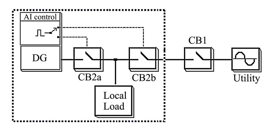
Figure 9.DG unit disconnection modes perturbations are observed.
We can also observe that the disconnect signal is generated before 14 electric cycles (233ms), and the algorithm effect on voltage TVHD is negligible before and after the islanding condition.
Similar traces are obtained for systems with one and six DG units. The time needed for the islanding confirmation (TIC) using the proposed algorithm in the systems working at unity power factor is presented in Table 2.
In this case we consider also that the DG and load power are matched. We can notice that this time is always lower than 2 seconds as recommended by the IEEE 1547-2003 standard. The simulation results show that the islanding event is confirmed faster for the systems with a high number of DG units.
As expected, the performance of the proposed method is increased if an active power mismatch is considered between the DG and the load. Table 3 shows the simulation results for the time needed for the islanding confirmation (TIC) in a system with 3 DG units operating at unity power factor. In this case, we consider different conditions of active power mismatch (12) between the DG and the load.
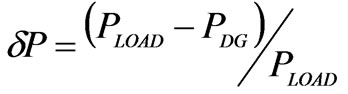 (12)
(12)
If dP is greater than 0.2 an important variation in the voltage measured at PCC is observed with the islanding condition. In this case the O/UVP acts and disconnects the DG units within 2 electric cycles.
4.2 Results for Islanding Detection in DG Power Factor Improvement Operation
For power factor improvement operation mode, the load RLC elements are calculated to produce an inductive power factor PF=0.95 and a quality factor qF=2.5. The DG system is configured to supply the active and reactive load powers.
The performance of the islanding detection method was evaluated for systems with 3 and 9 DG units operating in power factor improvement mode with different load power factors, and considering a high load quality factor (qF=2.5). In all simulated cases, as shown by Table 4, the
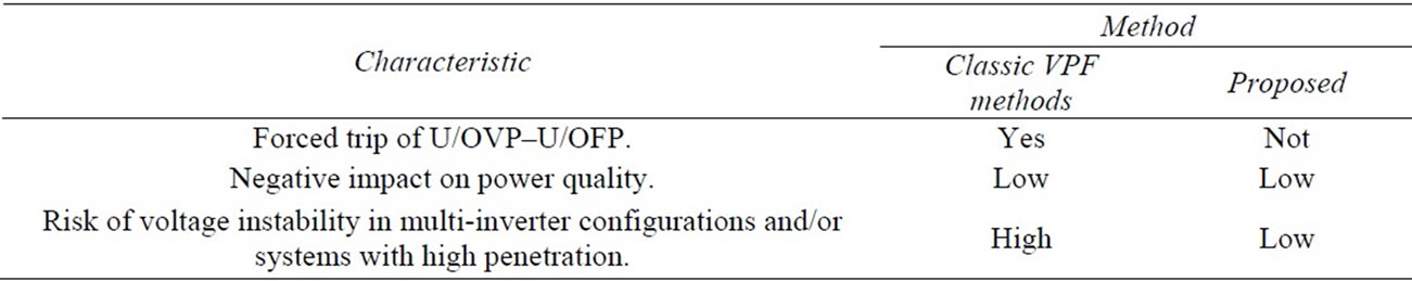
Table 1. Comparison of classic VPF methods and proposed method
islanding condition was confirmed within 13 electric cycles (216ms).
The simulation traces for a system with six DG units operating in the power factor improvement mode are presented in Figure 11. This simulation result shows that the proposed method offers fast detection of the islanding condition in the systems working in the power factor improvement mode; in this case the disconnection signal is generated within 11 electric cycles (183ms).
The performance of the proposed method was also evaluated in the power factor improvement mode, considering different load quality factor. In this case, we consider a system with 3 DG units operating in power improvement mode, with load power factor between 0.85 and 0.98 (0.85£PF£0.98), and load quality factor of 1.0, 1.5 and 2.5 (qF=1.0, qF=1.5, qF=2.5). The simulation results show that the time needed for the islanding confirmation is similar for different conditions of the load quality factor and the power factor. As shown in Table 4, the islanding confirmation in the simulated cases is reached within 12.5 electric cycles (208ms)
4.3 Results for Automatic Change of DG Operating Mode from Grid-Connected to Stand-Alone Mode after the Islanding Detection
We tested the performance of the proposed islanding detection method and observed the effect of the algorithm on the power quality when the stand-alone operation of DG is allowed after the islanding detection. In
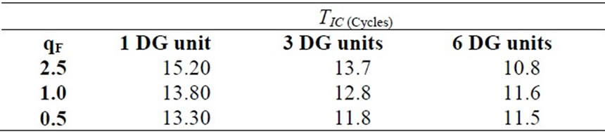
Table 2. Time necessary for the islanding confirmation using the proposed method in the systems operating at unity power factor
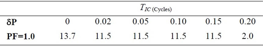
Table 3. Time necessary for the islanding confirmation using the proposed method in the systems with 3 DG units when the DG and load powers don’t match
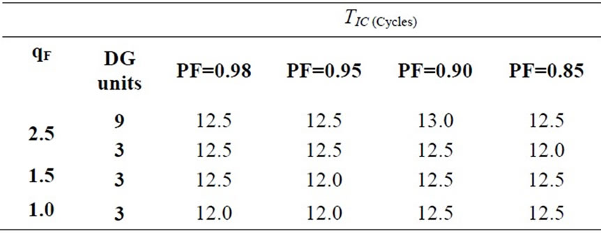
Table 4. Time necessary for the islanding confirmation using the proposed method in systems with 3 and 9 DG units operating in the power factor improvement mode
this case the AI protection opens the breaker CB2b to disconnect the DG system from the utility at the islanding confirmation.
Figure 12 shows the VPCC voltage and DG1 output current (IINV) traces before and after the islanding condition, the disconnection signal, the TCHD of the IINV and the TVHD of the VPCC for a system composed by four DG units. In this case, the DG system and load powers were matched, and the load elements were calculated for unity power factor (PF=1.0) and high quality factor (qF=2.5).
The simulation results show that the system can change its operational mode from grid connected mode to Stand-alone mode within a few cycles (10.75 cycles) after grid disconnection. The Total Current Harmonic Distortion (TCHD) and TVHD are always maintained at less than 2%. According the 1547-IEEE standard [4], the maximal allowed TCHD of DG is 5% and the TVHD measured at PCC must be less than 2.5%. As in the previous cases, the grid is disconnected at t=0. After the grid disconnection (t>0), the islanding detection algorithm produces the output power perturbation to detect the islanding condition. In this case, the islanding condition is confirmed and the disconnect signal is generated within 10.75 electric cycles. Then, at t=10.75 cycles, CB2 is opened and the system changes its operation mode from the grid-connected mode (on islanding condition) to the Stand-Alone mode. In the stand-alone mode, the voltage characteristics are imposed by the DG system output power. In the simulated case, the VPCC voltage reaches its nominal level in the stand-alone mode because the DG and load powers are matched. In a practical situation, and with a variable load power, the voltage and frequency control is possible by controlling the active
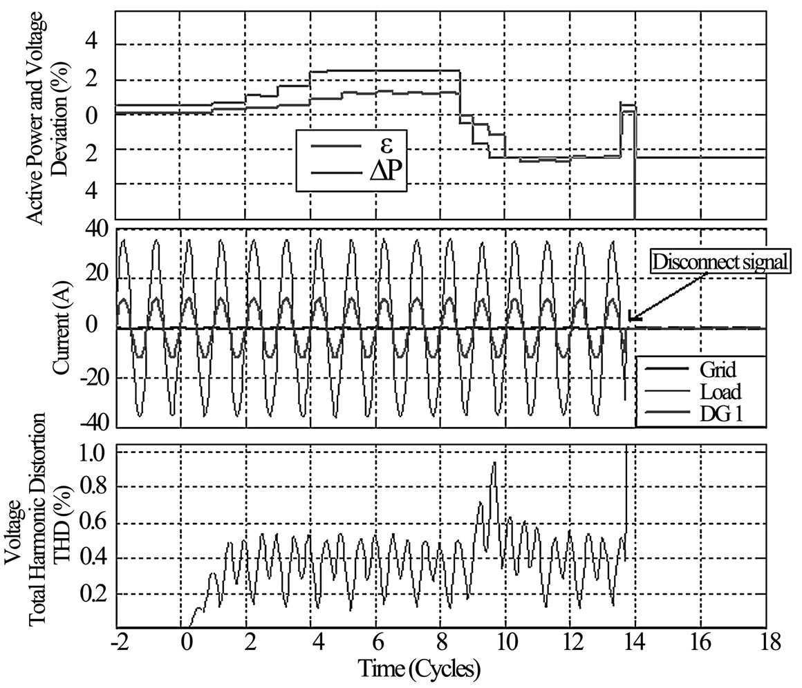
Figure 10. Simulation results for islanding detection on a three grid connected DG units system operating in unity power factor mode. Load PF=1.0 and qF=2.5
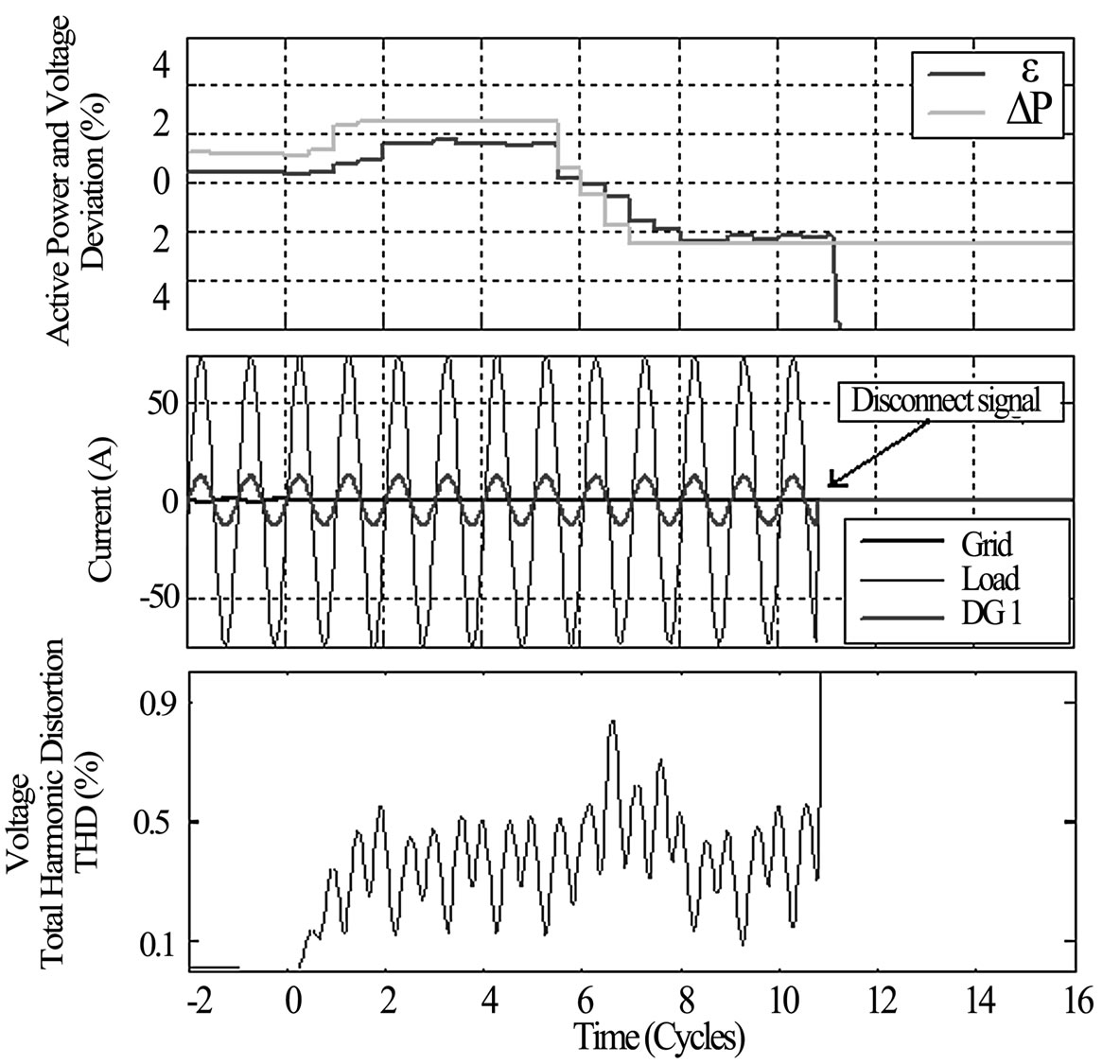
Figure 11. Simulation results for islanding detection for a system with six gridconnected DG units, operating in power factor improvement mode
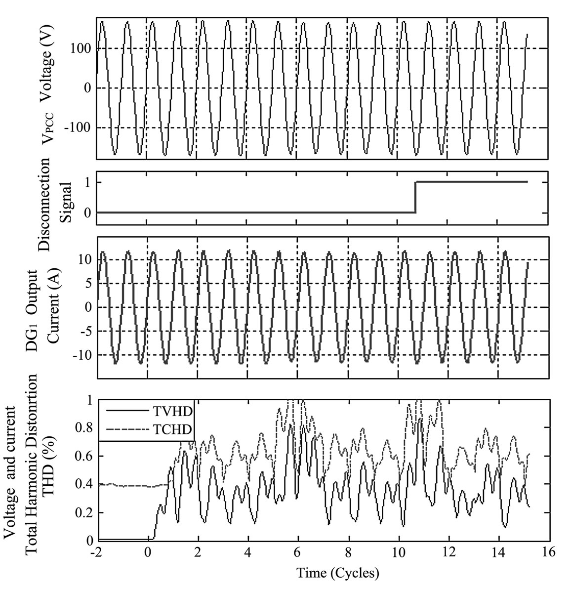
Figure 12. Simulation results for islanding detection and operational mode change from grid connected to stand-alone mode for four grid connected DG units system operating in unity power factor mode
and reactive output powers using the Voltage-Power Droop/Frequency-Reactive power Boost scheme (VPD/ FQB) as mentioned in [3] and as proposed in [17].
5. Conclusions
This paper presents an active islanding detection algorithm for multi-source DG systems. The proposed algorithm is based on the voltage positive feedback. Theoretical analyses are provided and simulation results show that the proposed islanding detection algorithm offers fast anti-islanding protection with negligible impact on power quality. This method may be useful for systems with single or multiple grid connected DG units. The synchronization between the different DG units is theoretically not required due to the fact that all units use a common variable to generate their local anti-islanding protection.
Considering its fast response and the negligible effect on power quality, this anti-islanding scheme could be used to allow the operation of the grid-connected distributed generation systems with safety disconnection. In contrast with commonly used methods, that force the voltage or frequency to the U/OVP or U/OFP trip limits,using the proposed islanding detection method makes possible the stand-alone operation of the DG system after the islanding is confirmed, and that without interruption of the load power.
The proposed method is easy and inexpensive to implant. The detection algorithm may be added to the pro gram of the power control unit to use the same digital processor.
Current and future works include the implementation of the algorithm using FPGA for the experimental validation under real and critical scenarios using multi-inverter configurations.
6. Acknowledgments
This work was supported by the LTE Hydro-Québec and the Natural Sciences and Engineering Research Council of Canada.
REFERENCES
- B. Kroposki, R. Lasseter, T. Ise, S. Morozumi, S. Papathanassiou, and N. Hatziargyriou, “Making microgrids work,” IEEE Power and Energy Magazine, Vol. 6, No. 3, pp. 40–53, 2008.
- K. Agbossou, M. Kolhe, J. Hamelin, and T. K. Bose,
- “Performance of a stand-alone renewable energy system based on energy storage as hydrogen,” IEEE Transactions on Energy Conversion, Vol. 19, No. 3, pp. 633–640, 2004.
- F. Katiraei, R. Iravani, N. Hatziargyriou, and A. Dimeas, “Microgrids management: Controls and operation aspects of microgrids,” IEEE Power and Energy Magazine, Vol. 6, No. 3, pp. 54–65, 2008.
- “IEEE standard for interconnecting distributed resources with electric power systems, IEEE standards,” in Standards Coordinating Committee 21 on Fuel Cells, Photovoltaics, Dispersed Generation, and Energy Storage, July 28, 2003.
- P. Mahat, C. Zhe, and B. Bak-Jensen, “Review of islanding detection methods for distributed generation,” Third International Conference on Electric Utility Deregulation and Restructuring and Power Technologies-DRPT, Vol. 1, pp. 2743–2748, 2008.
- W. Bower and M. E. Ropp, “Evaluation of islanding detection methods for utility-interactive inverters in photovoltaic systems,” Sandia Report SAND2002–3591, 2002.
- R. Bhandari, S. Gonzalez, and M. E. Ropp, “Investigation of two anti-islanding methods in the multi-inverter case,” IEEE Power and Energy Society General MeetingConversion and Delivery of Electrical Energy in the 21st Century, Vol. 1, pp. 1–7, 2008.
- C. Jeraputra, E. C. Aelwizal, P. N. Enjeti, and S. Choi, “An improved anti-islanding algorithm for utility interconnection of multiple distributed fuel cell powered generation,” Twentieth Annual IEEE Applied Power Electronics Conference and Exposition-APEC-2005, Vol. 1, pp. 103–108, 2005.
- O. Tsukamoto and K. Yamagishi, “Detection of islanding of multiple dispersed photovoltaic power systems,” Solar Energy, Vol. 58, No. 1–3, pp. 9–15, 1996.
- M. L. Doumbia, K. Agbossou, and D. Tran-Khanh-Viet, “Correlation technique investigation for islanding detection of inverter based distributed generation,” IEEE Power Electronics Specialists Conference-PESC2008, Vol. 1, pp. 4556–4561, 2008.
- Z. Chen and E. Spooner, “Voltage source inverters for high-power, variable-voltage DC power sources,” IEE Proceedings Generation, Transmission and Distribution, Vol. 148, No. 5, pp. 439–447, 2001.
- Z. Ye, L. Li, L. Garces, C. Wang, R. Zhang, M. Dame, R. Walling, and N. Miller, “A new family of active anti-islanding schemes based on DQ implementation for grid-connected inverters,” IEEE 35th Annual Power Electronics Specialists Conference–2004–PESC–04, Vol. 1, pp. 235–241, 2004.
- Z. Ye, R. Walling, L. Garces, R. Zhou, L. Li, and T. Wang, “Study and development of anti-islanding control for grid-connected inverters,” General Electric Global Research Center Niskayuna, New York, NREL/SR-560- 36243, 2004.
- M. E. Ropp, M. Begovic, and A. Rohatgi, “Analysis and performance assessment of the active frequency drift method of islanding prevention,” IEEE Transactions on Energy Conversion, Vol. 14, No. 3, pp. 810–816, 1999.
- S. J. Huang and F. S. Pai, “Design and operation of grid-connected photovoltaic system with power-factor control and active islanding detection,” IEEE Proceedings on Generation, Transmission and Distribution, Vol. 148, No. 2, pp. 243–250, 2001.
- X. Wang and W. Freitas, “Influence of voltage positive feedback scheme on inverter-based distributed generator stability,” IEEE Transactions on Power Delivery, Vol. 24, No. 2, pp. 972–973, 2009.
- C. K. Sao and P. W. Lehn, “Control and power management of converter fed microgrids,” IEEE Transactions on Power Systems, Vol. 23, No. 3, pp. 1088–1098, 2008.
Appendix
A. Grid and DG Units Characteristics
Grid voltage: 120V-60Hz Grid line inductance: Ls= 0.05mH DG type: IGBT-VSI, 1kW, 120V-60Hz
B. Setup of Islanding Detection Algorithm
∆PMAX= 2.5%, ∆PMIN = 0.5%, G = 3.0
∆PRC = 0.75%, ∆PAC = 2.25%, TMAX = 9 electric cycles DG Output filter: L=5mH, C=0.1mF