Int'l J. of Communications, Network and System Sciences
Vol.6 No.1(2013), Article ID:27464,8 pages DOI:10.4236/ijcns.2013.61006
Simple GUI Wireless Controller of Quadcopter
1Department of Mechatronic and Robotic Engineering, Faculty of Electrical and Electronic Engineering, University Tun Hussein Onn Malaysia, Batu Pahat, Malaysia
2Department of Power Engineering, Faculty of Electrical and Electronic Engineering, University Tun Hussein Onn Malaysia, Batu Pahat, Malaysia
Email: dr_dirman@yahoo.com
Received October 24, 2012; revised November 26, 2012; accepted December 20, 2012
Keywords: Quadcopter; GUI; Wireless; Arduino Uno; PID Controller
ABSTRACT
This paper presents the development of remotely operated Quadcopter system. The Quadcopter is controlled through a graphical user interface (GUI) where the communication between GUI and Quadcopter is constructed by using wireless communication system. The Quadcopter balancing condition is sensed by FY90 controller and IMU 5DOF sensor. For smooth landing, Quadcopter is equipped with ultrasonic sensor. All signals from sensors are processed by Arduino Uno microcontroller board and output from the Arduino Uno microcontroller board is implemented to control Quadcopter propellers. The GUI is designed using Visual Basic 2008 Express as interfacing communication between the Proportional, Integral and Derivative (PID) controller and the Quadcopter system. The experiment shows that the Quadcopter system can hover while maintain it balancing and the stability is guaranteed. Moreover, the developed system is able to cope with load disturbance up to 250 g during the hover position. Maximum operated time of Quadcopter is six minutes using 2200 mAh Lipo battery and operate time can be increased by using largest battery capacity.
1. Introduction
Research and development of unmanned aerial vehicle (UAV) and micro aerial vehicle (MAV) are getting high encouragement nowadays, since the application of UAV and MAV can apply to variety of area such as rescue mission, military, film making, agriculture and others. In US Coast Guard maritime search and rescue mission, UAV that attached with infrared cameras assist the mission to search the target [1]. Quadcopter or quad rotor aircraft is one of the UAV that is major focuses of active researches in recent years. Compare to terrestrial mobile robot that often possible to limit the model to kinematics, Quadcopter required dynamics in order to account for gravity effect and aerodynamic forces [2]. Quadcopter operated by thrust that produce by four motors that attached to it body. It has four input force and six output states (x, y, z, θ, ψ, ω) and it is an under-actuated system, since this enable Quadcopter to carry more load [3]. Quadcopter has the advantages over the conventional helicopter where the mechanical design is simpler. Besides that, Quadcopter changes direction by manipulating the individual propeller’s speed and does not require cyclic and collective pitch control [3,4].
2. Related Work
Nowadays, studies on UAV has attracted researchers and academia due to its broad of applications. One kind of UAV is Quadcopter. The research related to Quadcopter covers the areas of design, control, stability, communication systems and collision avoidance.
The using of GUI for controlling of Quadcopter has been widely used. Reference [5] studied on designing GUI control of UAV based on genetic algorithm (GA). The GUI developed is multi remote control and multi button. Reference [6] learned GUI control of Quadcopter for test purpose. The GUI is analyzed using GA. Reference [7] investigated GUI for convenient detection and control of the leak bottle detection equipment and embedded in ARM processor.
Reference [8] focused their study on the 3-DOF attitude control free-flying vehicle. The characteristic to be heavily coupled with inputs and outputs, and the serious non-linearity appear in the flying vehicle and due to this non-linear control, multi variable control or optimal control for the attitude control of flying Quadcopter. Reference [9] developed of nonlinear model and nonlinear control strategy for a 6-DOF Quadcopter aerial robot. The nonlinear model of Quadcopter aerial robot is based on Newton-Euler formalism. Model derivation comprises determining equations of motion of the Quadcopter in three dimensions and seeking to approximate actuation forces through modeling of the aerodynamic coefficients and electric motor dynamics. Reference [10] is done research on control of Quadcopter by visual tracking using stereo camera. The motion of a Quadcopter is control based on visual feedback and measurement of inertial sensor. In this research, active markers were finely designed to improve visibility under various perspectives. Figure 1 is the structure of Quadcopter controller done in this research. Reference [11] worked on intelligent fuzzy controller of Quadcopter. A fuzzy control is designed and implemented to control a simulation model of the Quadcopter. The inputs are the desired values of the height, roll, pitch and yaw. The outputs are the power of each of the four rotors that is necessary to reach the specifications. Simulation results prove the efficiency of this intelligent control strategy. References [12,13] are done research to analyze the dynamic characteristics and PID controller performance of a Quadcopter. This paper is describe the architecture of Quadcopter and analyzes the dynamic model on it. Besides that, this paper also designs a controller which aim to regulate the posture (position and orientation) of the 6-DOF Quadcopter.
3. Quadcopter Model
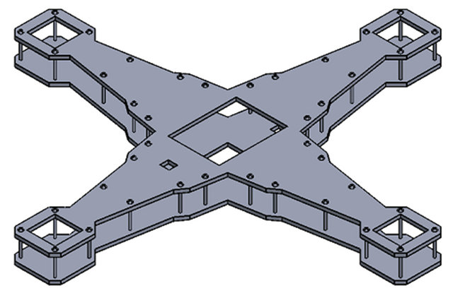
In this paper the frame of Quadcopter is build using aluminum plate. It is two layer of shape aluminum plate and connects together with bolts and nuts as this will make the frame of the Quadcopter become rigid and light-weight. Weight of the Quadcopter is proportional with it hover ability. Less weight will increase hover ability of it with minimum power consumption. This Quadcopter frame consist of a minimum area that just enough to place all the parts such as motor, controller board and batteries. Figure 2 shows Quadcopter frame

Figure 1. Schematic of Quadcopter.
 (a)
(a)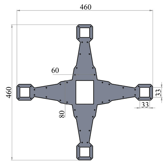 (b)
(b) (c)
(c)
Figure 2. (a) Quadcopter frame; (b) Top view; (c) Botom view.
mptio develop.
While the physical form of the Quadcopter develop is described in Figure 3.
To produce optimal performance of the Quadcopter, weight and thrust output of each motor used are calculated by using the motor calculation software provided by Motrolfly. These are obtained through key in the parameters of motor, power source and propeller size.
4. Quadcopter Mathematical Model
Schematic dynamical of Quadcopter is represented in

Figure 3. Physical form of Quadcopter system.
Figure 1 and based this mathematical model of Quadcopter dynamics are derived [14,15].
Where,  is sum of the thrust of each motor. Th1, Th2, Th3 and Th4 are thrust generated by front, rear, left and right motor respectively. m is Quadcopter mass, g is the gravity acceleration and
  is the half length of Quadcopter. x, y and z are the three axis potion.
  are three Euler angles representing pitch, roll and yaw.
The dynamics formulation of Quadcopter moving from landing position to a fixed point in the space is given as:
 (1)
(1)
where,  is a matrix transformation,

By applying the force and moment balance laws, Quadcopter motion formulations are given as in Equations (2) till (4).
 (2)
(2)
 (3)
(3)
 (4)
(4)
where  is drag coefficient (assume zero since drag is negligible at low speed).
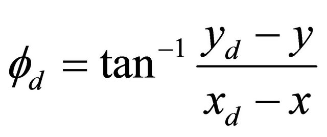
The angle movement of Quadcopter is illustrated in Figure 4.
The angle  and
and  are determined as the following:
 (5)
(5)
 (6)
(6)
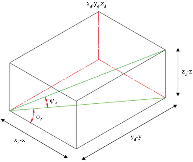
Figure 4. Angle movement of Quadcopter.
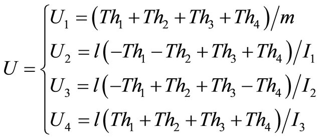
Quadcopter has four controller input ,
,  ,
,  and
and . Each of the affects the attitude, rotation in roll angle, rotation in pitch angle and yaw angle respectively. And equation of them as given as below:
 (7)
(7)
where  is thrust generated by four motor,
  is the force to moment scaling factor and
  is the moment of inertia with respect to the axes. Then the second derivatives of each angle are:
 (8)
(8)
 (9)
(9)
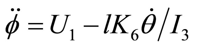 (10)
(10)
5. Quadcopter Controller
In this paper, to control Quadcopter altitude motion, PID controller has been developed and embedded in Arduino Uno. PID control will maintain the distance of Quadcopter altitude motion based on input from ultrasonic sensor. Ultrasonic sensor will sense the distance between Quadcopter and ground, then send this output signal to Arduino Uno board for controlling the throttle. Figure 5 shows the block diagram of Quadcopter altitude control.
6. Simple GUI Design of Quadcopter Control
The graphical user interface (GUI) is a type of user interface that allows users to interact or communicate with electronic devices using images rather than text
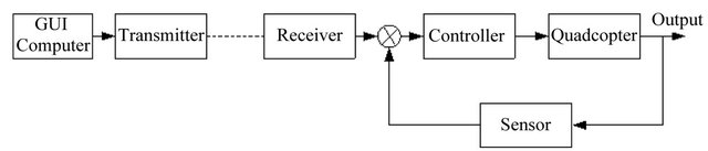
Figure 5. Quadcopter controller.
commands [16]. In this work the GUI is design for communicating tools between the human as operator and Quadcopter movement. The command as input of the Quadcopter controller will be inputted by the operator through GUI. There are four movements of Quadcopter that will control. They are throttle for altitude movement, rudder for yaw movement, aileron for roll movement, and elevator for pitch movement. Figure 6 describes the Quadcopter GUI controller develops.
7. Quadcopter Wireless Communication
Input data to Quadcopter control is send through wireless communication system. The XBee wireless communication module is used. The data is inputted using GUI and consist of throttle for altitude movement, rudder for yaw movement, aileron for roll movement, and elevator for pitch movement as in Figure 2. From GUI, data is transmitted to transmitter at computer and received by receiver at Quadcopter. Based on that data controller send command signals to Quadcopter propeller and Quadcopter responses are sensed using ultrasonic sensor and gyro to ensure achievement of controller objectives. Figure 7 describes the connection between Arduino Uno board and XBee board.
The PID controller was applied since it is one type of widely used controller [17]. The PID controller is the most common form of feedback. The PID controllers are today found in all areas where a control is used. Their useful functions are sufficient for a large number of process applications and the transparency of the features leads to wide acceptance by the users. On the other hand, it can be shown that the internal mode control (IMC) framework leads to PID controllers for virtually all models common in practice [17,18]. PID control is an important ingredient of a distributed control system.
The PID algorithm is describe as
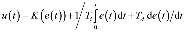 (11)
(11)
where, y is the measured process variable, r is the reference variable,  is the control signal and e is the control error
 . The reference variable is often called the set point
 .
.
The control signal is thus a sum of three terms: the P-term (which is proportional to the error), the I-term
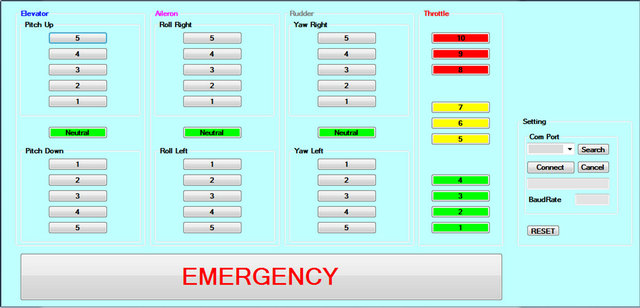
Figure 6. Quadcopter GUI controller.
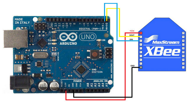
Figure 7. Xbee and Arduino Uno connection.
(which is proportional to the integral of the error), and D-term (which is proportional to the derivative of the error). The controller parameters are proportional gain K, integral time , and derivative time
 . In general form the PID algorithm can be represented by the transfer function below:
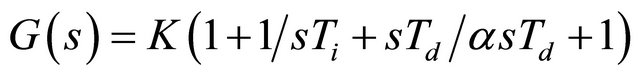 (12)
(12)
where,  typically takes a value of 1/10. This type of controller is called interacting controller and it is easier to be tune manually [17]. Figure 8 shows the block of the PID controller related to previous equation.
8. Result and Analysis
In order to verify the GUI controller develops, two tests have been done. They are the Quadcopter roll axis disturbance and Quadcopter pitch axis disturbance.
8.1. Quadcopter Roll Axis Disturbance Test
First test is done for hover movement on roll axis of Quadcopter controller performance to varies load as a disturbance condition. The results are represented in Figures 9-14. Each figure describes the response of
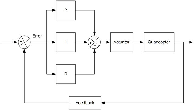
Figure 8. Block of Quadcopter PID controller.

Figure 9. Roll axis hover test response for no load.
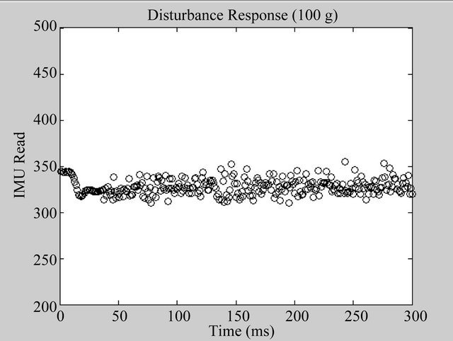
Figure 10. Roll axis hover test response for load 100 g load.
Quadcopter controller response related to amount of load as a disturbance that is provided to it.
Quadcopter can maintain it balance and stability till amount of up to 200 g as in Figures 9-12. Even though some of output data is not in straight line, but most of data are in the range.
For the load 250 g and above, the Quadcopter cannot balance itself as represented in Figures 13 and 14. The

Figure 11. Roll axis hover test response for 150 g load.
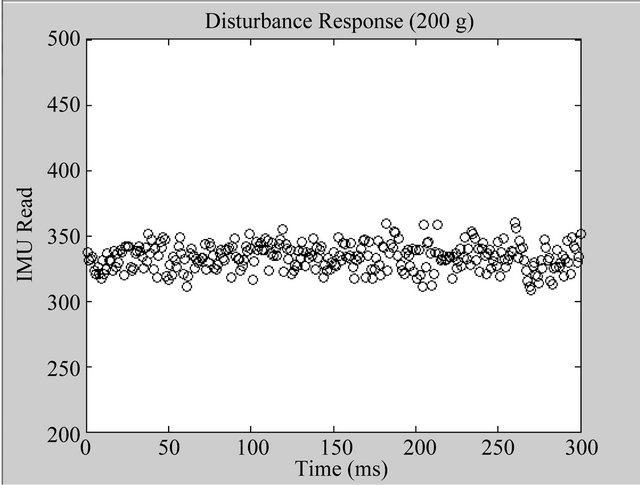
Figure 12. Roll axis hover test response for 200 g load.
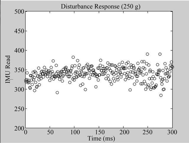
Figure 13. Roll axis hover test response for 250 g load.
responses are spread away and not gather in straight line. Quadcopter is not able to balance itself and lost stability. It means the maximum amount of load of Quadcopter designed for roll axis hover is 200 g.
8.2. Quadcopter Pitch Axis Disturbance Test
The second test of Quadcopter is pitch axis disturbance test. The test is done in same method with previous test by applied varies amount of load to Quadcopter as a disturbance while Quadcopter is doing pitch axis hover. The test results are described in Figures 15-20.
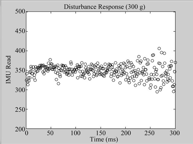
Figure 14. Roll axis hover test response for 300 g load.

Figure 15. Pitch axis hover test response for no load.

Figure 16. Pitch axis hover test response for 100 g load.
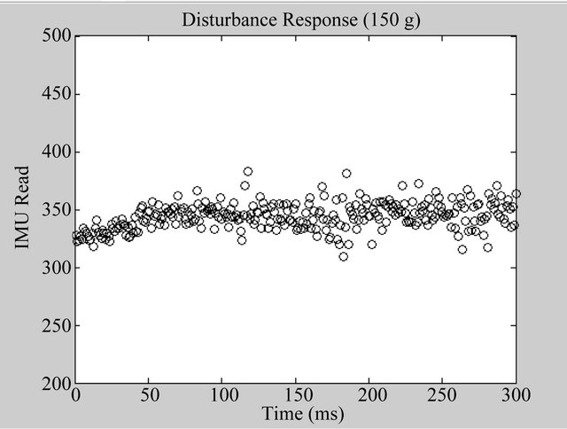
Figure 17. Pitch axis hover test response for 150 g load.
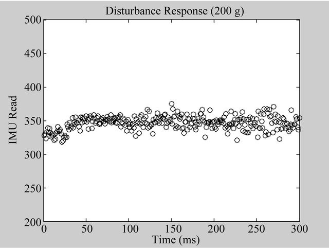
Figure 18. Pitch axis hover test response for 200 g load.

Figure 19. Pitch axis hover test response for 250 g load.
Table 1 shows the summary of the load amount as a disturbance test result for roll and pitch axis hover of Quadcopter.
From the table above, Quadcopter can maintain it sta-

Figure 20. Pitch axis hover test response for 300 g load.
Table 1. Summarize of disturbance test result.
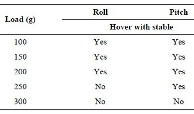
bility with load applied up to 200 g for roll axis hover and up to 250 g for pitch axis hover. It means Quadcopter designed able to operate in balance and stable condition till 200 g load.
9. Conclusion
Quadcopter and its GUI controller have been successfully constructed and developed. Based the test results, GUI controller able to send the control signal to Quadcopter controller and Quadcopter controller can translate the command signal to maintain its stability and balance. The Quadcopter developed able to accept load disturbance up to two hundred and fifty grams during hovering position.
10. Acknowledgements
This work has been supported by Office of Research Innovation Commercialization and Consultancy (ORICC) Universiti Tun Hussein Onn Malaysia under project vot. no. 1077.
REFERENCES
- A. Ryan and J. K. Hedrick, “A Mode-Switching Path Planner for UAV-Assisted Search and Rescue,” Proceeding of the 44th IEEE Conference on Decision and Control, and the European Control, Seville, 12-15 December 2005, pp. 1471-1476. doi:10.1109/CDC.2005.1582366
- A. L. Salih, M. Moghavvemil, H. A. F. Mohamed and K. S. Gaeid, “Flight PID Controller Design for a UAV Quadcopter,” Scientific Research and Essays, Vol. 5, No. 23, 2010, pp. 3660-3667.
- A. Z. Azfar and D. Hazry, “Simple GUI Design for Monitoring of a Remotely Operated Quadcopter Unmanned Aerial Vehicle,” Proceeding of the 7th International Colloquium on Signal Processing and its Applications (CSPA), Penang, 4-6 Mach 2011, pp. 23-27.
- K. W. Weng, “Quadcopter,” Robot Head to Toe Magazine, Vol. 10, 2011, pp. 1-3.
- T. Mori, T. Nonaka and T. Hase, “Design Method of GUI Using Algorithm,” Proceeding of the IEEE International Conference on System Man and Cybernatics (SMC), 10-13 October 2010, pp. 3200-3204. doi:10.1109/ICSMC.2010.5642282
- A. Rauf, S. Anwar, M. A. Jaffer and A. A. Shahid, “Automated GUI Test Coverage Analysis Using GA,” Proceeding of the 7th International Conference on Information Technology: New Generation (ITNG), 12-14 April 2010, pp. 1057-1062. doi:10.1109/ITNG.2010.95
- L. Sun, H. Xie and K. Chen, “Design and Realization of GUI-Control for Leak Detection Equipment,” Proceeding of the International Conference on Electronic, Communication and Control (ICECC), 9-11 September 2011, pp. 3638-3641. doi:10.1109/ICECC.2011.6067556
- D. Park, M.-S. Park and S.-K. Hong, “A Study on the 3-DOF Attitude Control of Free-Flying Vehicle,” Proceeding of the IEEE International Symposium on Industrial Electronics (ISIE), Pusan, 12-16 June 2001, Vol. 2, pp. 1260-1265.
- A. A. Mian and W. Daobo, “Nonlinear Flight Control Strategy for an Underactuated Quadrotor Aerial Robot,” Proceeding of the IEEE International Conference on Networking, Sensing and Control (ICNSC), Sanya, 6-8 April 2008, pp. 938-942. doi:10.1109/ICNSC.2008.4525351
- M. Achtelik, T. Zhang, K. Kuhnlenz and M. Buss, “Visual Tracking and Control of a Quadcopter Using a Stereo Camera System and Inertial Sensors,” Proceeding of the International Conference on Mechatronics and Automation (ICMA), 9-12 August 2009, pp. 2863-2869. doi:10.1109/ICMA.2009.5246421
- M. Santos, V. López and F. Morata, “Intelligent Fuzzy Controller of a Quadrotor,” Proceeding of the IEEE International Conference on Intelligent Systems and Knowledge Engineering (ISKE), Hangzhou, 15-16 November 2010, pp. 141-146. doi:10.1109/ISKE.2010.5680812
- I. Morar and I. Nascu, “Model Simplification of an Unmanned Aerial Vehicle,” Proceeding of the IEEE International Conference on Automation Quality and Testing Robotics (AQTR), Cluj-Napoca, 24-27 May 2012, pp. 591- 596. doi:10.1109/AQTR.2012.6237779
- J. Li and Y. T. Li, “Dynamic Analysis and PID Control for a Quadrotor,” Proceeding of the International Conference on Mechatronics and Automation (ICMA), Beijing, 7-10 August 2011, pp. 573-578. doi:10.1109/ICMA.2011.5985724
- A. K. Cooke, I. D. Cowling, S. D. Erbsloeh and J. F. Whidborne, “Low Cost System Design and Development an Autonomous Rotor Vehicle,” Proceeding of the 22nd International Conference on Unmanned Air Vehicle Systems, Bristol, 16-18 April 2007, pp. 281-289
- C. Balas, “Modelling and Linear Control of Quadcopter,” M.S. Thesis, Cranfield University, Cranfield, 2007.
- L. Yang, Y. Choi, C. Seo, T. Yang and M. S. Kim, “Design of VY: Mini Visual IDE for the Development of GUI in Embedded Devices,” Proceeding of the 5th ACIS International Conference on Software Engineering Research Management & Application, 20-22 August 2007, pp. 625-632. doi:10.1109/SERA.2007.76
- M. A. Johnson and M. H. Moradi, “PID Control,” SpringerVerlag, London, 2005.
- D. Hanafi, “PID Controller Design for Sem-Active Car Suspension Based on Model from Intelligent System Identification,” Proceeding of the IEEE International Conference on Computer Engineering and Applications (ICCEA), Bali, 19-21 Mach 2010, pp. 60-63. doi:10.1109/ICCEA.2010.168