Journal of Biomedical Science and Engineering
Vol.6 No.8(2013), Article ID:35603,11 pages DOI:10.4236/jbise.2013.68099
The effects of stent porosity on the endovascular treatment of intracranial aneurysms located near a bifurcation
![]()
1Department of Mechanical Engineering, University of Hong Kong, Hong Kong, China
2Division of Neurosurgery, Department of Surgery, Li Ka Shing Faculty of Medicine, University of Hong Kong, Queen Mary Hospital, Hong Kong, China
3Department of Neurosurgery, Kwong Wah Hospital, Hong Kong, China
4Medical Engineering Program, Department of Electrical and Electronic Engineering, University of Hong Kong, Hong Kong, China
Email: abmtang@hku.hk
Copyright © 2013 Abraham Yik-Sau Tang. This is an open access article distributed under the Creative Commons Attribution License, which permits unrestricted use, distribution, and reproduction in any medium, provided the original work is properly cited.
Received 31 May 2013; revised 10 July 2013; accepted 21 July 2013
Keywords: Intracranial aneurysm; Endovascular Treatment; Stent; Stent Porosity; Computational Fluid Dynamics
ABSTRACT
Intracranial aneurysm occurs when a cerebral artery develops an abnormal sac-like dilatation, and will cause massive bleeding in the subarachnoid space upon rupture. Endovascular stenting is a minimally invasive procedure in which a flow-diverting stent is deployed to cover the aneurysm neck, thereby restricting blood from entering the aneurysm and reducing the risk of rupture. The stent porosity, a crucial factor determining the intra-aneurysmal hemodynamics following treatment, is investigated by computational fluid dynamics techniques. Based on the computational results, a low porosity stent will dramatically reduce the flow velocity and the flow rate inside the side branch vessel. Conversely, a high porosity stent may not provide adequate flow reduction inside the aneurysm, possibly causing treatment failure. An advisable range of optimal stent porosity would be 60% to 75%, which can drastically reduce the flow rate into the aneurysm while preserving enough blood flow for the side branch vessel. Clinically, deployment of two or more flow-diverting stents may not increase treatment efficacy but can potentially lead to adverse effects due to side-branch hypoperfusion. The present quantitative analysis can also provide practical insight for future stent design.
1. INTRODUCTION
Aneurysms are abnormal focal dilatations of human blood vessels that may constitute dangerous pathological conditions. Intracranial aneurysms are commonly found near the Circle of Willis in the brain. The weakened aneurysmal wall may rupture and will cause severe subarachnoid hemorrhage (a kind of severe hemorrhagic stroke) [1,2]. The prevalence of intracranial aneurysm is about 5% [2,3], and this is associated with high mortality and morbidity rates upon rupture [1,2,4].
Saccular intracranial aneurysms are commonly located near the bifurcation point of the arteries [4-6]. The ultimate goals of treatment are the obliteration of the aneurysmal lumen and reduced risk of rupture. In open surgery procedure, applying a clip across the neck of aneurysm will occlude the inflow of blood into the aneurysm. With the development of endovascular intervention technique in the past two decades, most aneurysm sacs can now be occluded by micro-coils, which are delivered through intravascular microcatheters. When the lumen of aneurysm is occluded, blood from the main circulation cannot enter and the risk of rupture is mitigated. Another recent development is the flow-diverting stent, which is deployed in the segment of vessel harbouring the aneurysm [7]. This stent vastly reduces the blood flow entering the aneurysm and induces flow stasis inside the sac. As the aneurysmal sac becomes isolated from the blood circulation, risk of aneurysm rupture is thus reduced [8]. Consequently, the effect of endovascular stenting on the hemodynamics within the aneurysm and the nearby vasculature is of clinical significance and deserves careful studies.
The porosity of the stent is important. A stent of low porosity will drastically reduce the flow entering the aneurysm, but may also lead to significant flow reduction in the side branch, resulting in possibly permanent damage of the organs downstream. Complete occlusion of the side branch vessel might also occur after stenting in extreme cases [9]. Consequently, the flow-diverting stent should be designed such that flow inside the aneurysm is minimized while sufficient flow to the side branch is preserved.
This paper is the first report which investigates a wide range of stent porosity for the bifurcation model, a common geometry of an intracranial aneurysm, under pulsatile flow condition. Flows in both the aneurysm and the side branch vessel are considered. The issue of optimal stent porosity will be addressed quantitatively by performing computational fluid dynamics (CFD) simulations. In fact, computational investigation with finite element or finite volume approach is a widely used noninvasive tool in medical engineering [10-14].
Indeed, intensive CFD studies of intracranial aneurysm have been performed earlier in the literature. Perktold et al. analyzed the flow rates in a Y-shaped model under pre-stenting situation [6]. Liou et al. studied helix and mesh types stent configurations [15]. Seshadhri et al. tested the Neuroform stents and the Silk stent with steady blood flow conditions [16]. In addition, Shobayashi et al. investigated several stent designs with closed-cell structure mechanically using the finite element method (FEM) [17]. Babiker et al. compared different stent configurations using a bifurcation model without testing the stent porosity quantitatively [18]. Bernardini et al. determined the hemodynamics of post-stenting cerebral aneurysm by different computational approaches [19,20]. Moreover, the geometry of the aneurysm and the parent vessel vasculature had also been studied [21-24].
On the other hand, investigations of varying stent porosity had been carried out without a bifurcation of blood vessels. Experiments using particle image velocimetry were conducted to visualize the blood flow. Yu et al. tested the porosity of stents and springs ranging from 45% to 78% using the steady flow assumptions [25]. Rhee et al. considered lateral and fusiform aneurysm models, and compared stents with porosity of 79% and 86% [26]. Furthermore, Lieber et al. focused on the stent porosity ranging from 76% to 85%. The results suggested that a low porosity stent could lead to a reduction in aneurysmal vortex speed and smaller interaction with the parent vessel flow in both large and small arteries [27]. Augsburger et al. investigated stent porosity of 45% to 100%, and concluded that a low porosity stent could reduce the intra-aneurysmal flow significantly [28]. Liou et al. examined a range of stent porosities from 25% to 100% using CFD and experiments, and claimed that a stent with extremely low porosity might not reduce the aneurysm inflow rate very effectively [29]. Kim et al. studied the multiple stent deployment with patient specific model, and concluded that stent design and porosity were important in altering the hemodynamic parameters of the aneurysm [30]. These studies mainly focused on sidewall aneurysms being located on a straight blood vessel, without considering a side branch vessel nearby. Janiga et al. tested two stent porosities and different stent locations with patient specific models [31]. From a clinical perspective, Sadasivan et al. deployed flow-diverting stents in intracranial aneurysms in rabbits. Both stent porosities and variations with the actual number of pores per unit area were tested. However, the stent porosity studied was limited to a 65% to 70% range [32].
The Pipeline Embolization Device (PED) is a commercially available flow-diverting stent with a metallic surface coverage ranging from 30% to 35%, which implies a stent porosity of 65% to 70% [33]. A Silk stent, however, would have a lower porosity ranging from 45% to 65% [34]. Other products like Neuroform stent can have porosities of 67% and 83% [16]. High porosity device like the Wallstent and the Tristar stent will have porosities of 82% and 84%, respectively [35]. During the clinical operation, surgeons can adjust the effective porosity by controlling the number of stents deployed at the same position [9]. If two flow-diverting stents are implanted at the same position, the metallic surface coverage at the neck of the aneurysm increases almost twofold, and will thus reduce the porosity by half [36,37].
The objective of our study is to investigate the blood flow dynamics of stent deployment in an idealized Y-shaped configuration, a common geometry of the cerebral arteries [1]. Nine different values of porosity, ranging from 35% to 100%, are tested. In addition, the flow velocities and the volume flow rates for different stent porosities are evaluated, providing quantitative information for side branch perfusion and rupture risk assessment. The shear stress levels near the aneurysm neck are also assessed, as extremely low level of such stresses may lead to long term damage of endothelial cells or other undesirable pathological consequences [38-41]. Shear forces acting on the stent along the flow direction are important, as they might cause stent migration and eventually treatment failure [42,43].
2. METHODS
Hemodynamics of the cardiovascular system is generally difficult to analyze, mainly due to the highly irregular vasculature geometry and the pulsatile nature of blood flow. Computational fluid dynamics techniques and increasingly sophisticated software are frequently employed recently to assist clinical personnel in making therapeutic decision, as in vivo measurements are usually difficult to conduct.
Three pieces of software were adopted in the current study. A computer-aided design software SOLIDWORKS 2011 (Concorde, Massachusetts, USA) was used to generate a high quality three-dimensional model. The task of mesh generation with mesh quality control was performed by GAMBIT 2.4.6 (developed by FLUENT). For the task of blood flow simulation, the software FLUENT 6.3.26 (ANSYS, Canonsburg, Pennsylvania, USA) had been utilized.
2.1. Geometrical Model
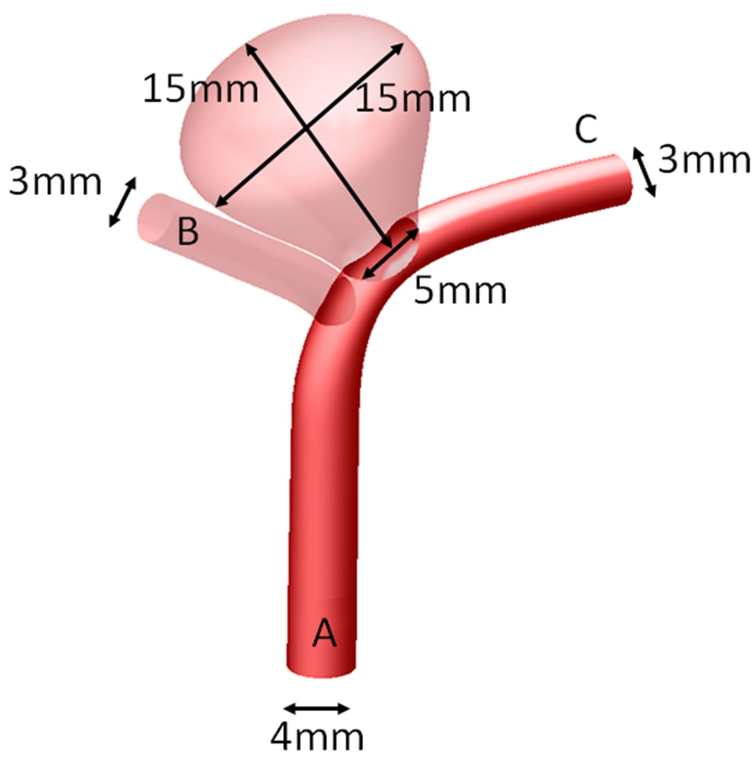
An idealized configuration with an aneurysm located near the tip of a bifurcation (Figure 1(a)), which commonly occurs in many patients, is adopted as the numerical model [6]. Referring to real human anatomy, the diameters of the proximal parent artery (position “A”), the side branch vessel on the left (position “B”) and the distal parent vessel on the right (position “C”), were set with values of 4 mm, 3 mm and 3 mm, respectively. The dimensions for the height, dome (maximum diameter) and the neck of the aneurysm were set as 15 mm, 15 mm and 5 mm, respectively (Figure 1(a)). The aspect ratio (aneurysm height/aneurysm neck) thus attained the value of 3. From previous studies [44-46], such high aspect ratio intracranial aneurysms may suffer from a higher chance of rupture.
Simulating endovascular treatment of aneurysm, a flow-diverting stent is deployed to cover the aneurysm neck and the side branch vessel on the left (Figure 1(b)) [47]. The porosity of the stent will then be varied from 35% to 100%. The 100% porosity case implies a nonstenting situation, and the 35% porosity represents the two Pipeline stents situation, with metallic surface coverage almost doubling that of the one-stent case.
The stent is a mesh-like device, which is constructed via the software SOLIDWORKS, and the stent would conform to the vessel curvature. Each closed-cell is postulated to be the shape of a rhombus, which is a reasonable assumption for both Pipeline stent and Silk stent. The stent thickness and the width of each stent strut were 0.1 mm and 0.07 mm, respectively. In fact, a commercial stent can have a stent strut size ranging from 0.03 mm (Silk stent) to 0.1 mm (Neuroform stent) [16]. The size of the rhombus would be varied to produce the necessary range of porosity from 35% to 100% (Figure 1(c)). Furthermore, the thickness of the stent is assumed to be constant. The elasticity of the stent is ignored here, and would be addressed in future research.
2.2. Governing Equations
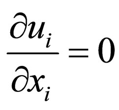
The three dimensional fluid flow is governed by the continuity equation and the Navier-Stokes (NS) equations [1] (as usual, repeated indices = summation):
 , (1)
, (1)
 (a)
(a)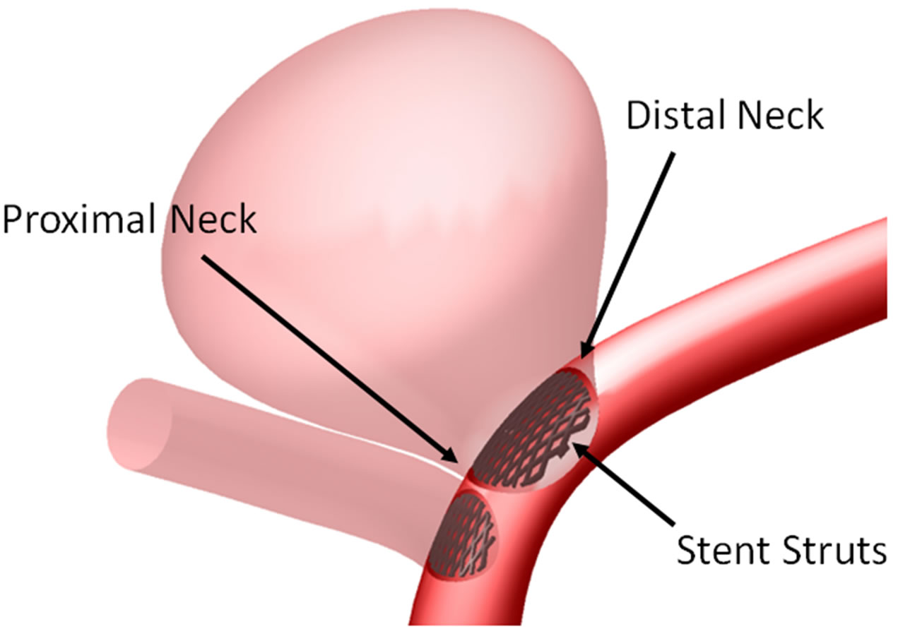 (b)
(b)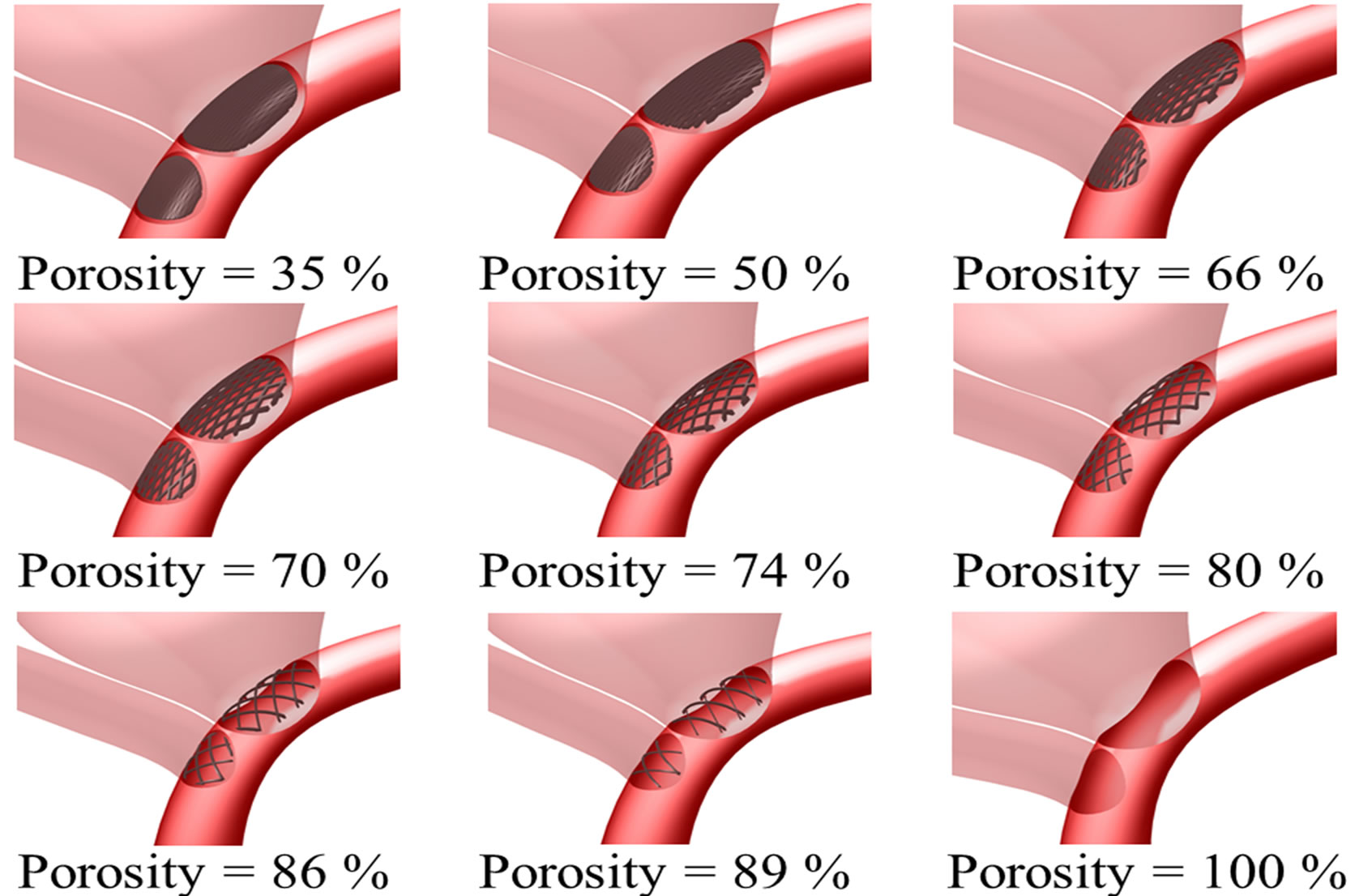 (c)
(c)
Figure 1. Intracranial aneurysm model considered in this investigation. (a) Geometry and dimensions; A, B, and C respectively denote proximal parent artery, side branch vessel, and distal parent artery; (b) Illustration of stent deployment that encompasses the aneurysm neck in the distal parent artery; (c) Three dimensional perspective of intracranial aneurysm model with stent porosities ranging from 35% to 100% (the last case is essentially the pre-deployment scenario).
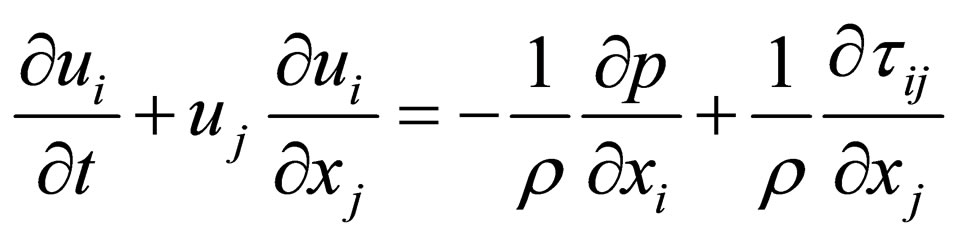 , (2)
, (2)
where ui (i = 1, 2, 3) are the components of the velocity vector, ρ = fluid density, p = pressure, and τij = normal and shear stresses. These equations are iteratively solved by the unsteady flow solver of the software FLUENT. The time step size is set to be 0.001 second, with a continuity residual error of 10−6.
2.3. Spatial Grid Sizes
To preserve proper resolution, the number of elements should be carefully selected. Here, the spatial grid size ranged from 0.032 mm to 0.3 mm, due to the variation of the complexity of the pre-operation (nonstented) and post-operation (stented) models. Tetrahedral elements are employed [16,31]. For the stented models, further refinement of the spatial grid size is essential for low stent porosity cases in order to maintain the quality of the mesh. The numbers of elements are indicated in Table 1.
The accuracy of the computational results was validated by performing mesh independence tests. The preoperative configuration and the 89% porosity case were taken as representative examples. For each model, three different grid sizes were tested and the results were summarized in Table 2. From these data, the models with 780,903 grids (porosity = 100%) and 2,007,881 grids (porosity = 89%) were taken as sufficiently accurate, as the results are unlikely to be altered by further mesh refinement.
2.4. Fluid Properties and Boundary Conditions
Blood plasma is treated as a continuum. All the suspended particles, like the blood cells and platelets, were ignored since they are small compared to the size of the blood vessels (3 - 4 mm). In addition, blood is assumed to be an incompressible and Newtonian fluid [39]. The density and the dynamic viscosity were assumed to be 1060 kg·m−3 and 0.0035 kg·m−1·s−1 respectively [48,49].
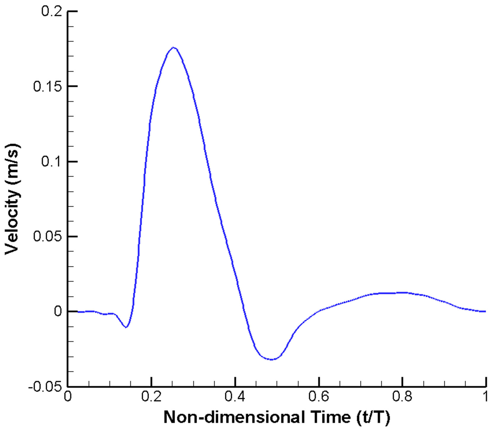
A widely used scheme of imposing velocity inlet and pressure outlet boundary conditions is adopted. A velocity profile pulsatile in time (but uniform in space) (Figure 2(a)) is prescribed at the inlet [10,50,51]. Similarly, a pulsatile pressure waveform with realistic blood pressure of 122/82 mmHg (1 mmHg = 133.3 Pa) is imposed at the outlets (Figure 2(b)) [51,52]. Moreover, all the vessel walls are assumed to be rigid and satisfy the noslip condition [53].
The cardiac cycle (T) was selected as 0.8 second, assuming a patient with a heart rate of 75 beats per minute [51,52]. At the moment of systole (t/T = 0.25), the Reynolds number is 215, based on the diameter of inlet (4 mm), the peak velocity (0.178 m·s−1) and the blood viscosity (0.0035 kg·m−1·s−1) [54,55]. Thus the flow can be treated as laminar. In addition, the Womersley number, a dimensionless parameter indicating the pulsating effect of the flow, is 6.2.
The results reported here are referring to data extracted during the third cycle of computations, since periodic output can typically be produced after two cycles of calculations. Furthermore, unless specified otherwise, the properties stated subsequently are those at the moment of systole, i.e. t/T = 0.25.
3. RESULTS AND DISCUSSIONS
A stent of low porosity will achieve reduction of flow into the aneurysm, but may unfortunately impede blood supply to the side branch as well. Hence attaining an optimal stent porosity is critical, and the simulation results presented below demonstrate that a porosity in the range of 60% to 75% might be optimal. Relevant factors to consider are 1) velocity and pressure inside the aneurysm and in the side branch vessel; 2) wall shear stress on the aneurysmal wall and the vessel walls; 3) stent migration force; and 4) volume flow rates into the aneurysm and the side branch vessel.
3.1. Velocity and Pressure
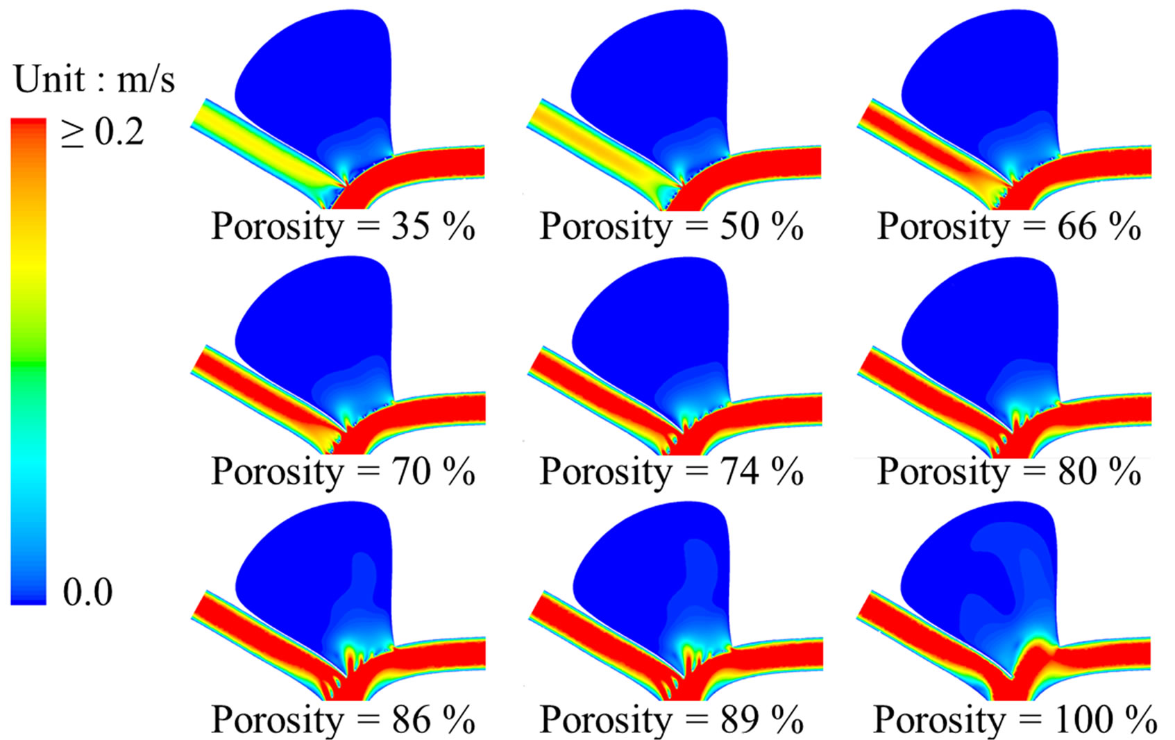
Both the flow patterns (streamline contours) and the magnitude of velocity are dramatically altered by the metallic stent (Figure 3). Before stenting, the flow will impinge onto the distal neck of the aneurysm and eventually will leave the aneurysm through the proximal neck. The flow pattern, however, changes completely after stenting. For the post-operative cases, blood enters the aneurysm near the proximal neck while leaving the aneurysm near the distal neck, and the flow speed near the apex of the aneurysm is suppressed. These flow patterns are remarkably similar to the results obtained by Liou et al. [29]
After stenting, the maximum velocity near the stent ranges from 0.305 m·s−1 (porosity of 35%) to 0.318 m·s−1 (porosity of 89%). This can be contrasted with a value of 0.277 m·s−1 in that area for the pre-operation model. This small increment in flow speed results from the local reduction of area due to the stent, but is unlikely to cause severe damage to the aneurysm wall.
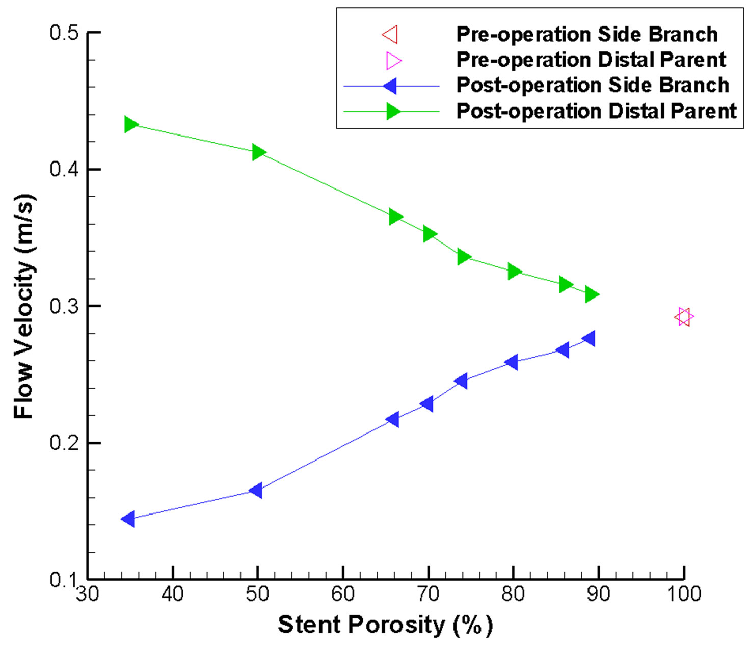
As expected, the maximum flow velocity in the side branch is reduced after stenting, and drops dramatically when the stent porosity decreases (Figure 4(a)). This ve-
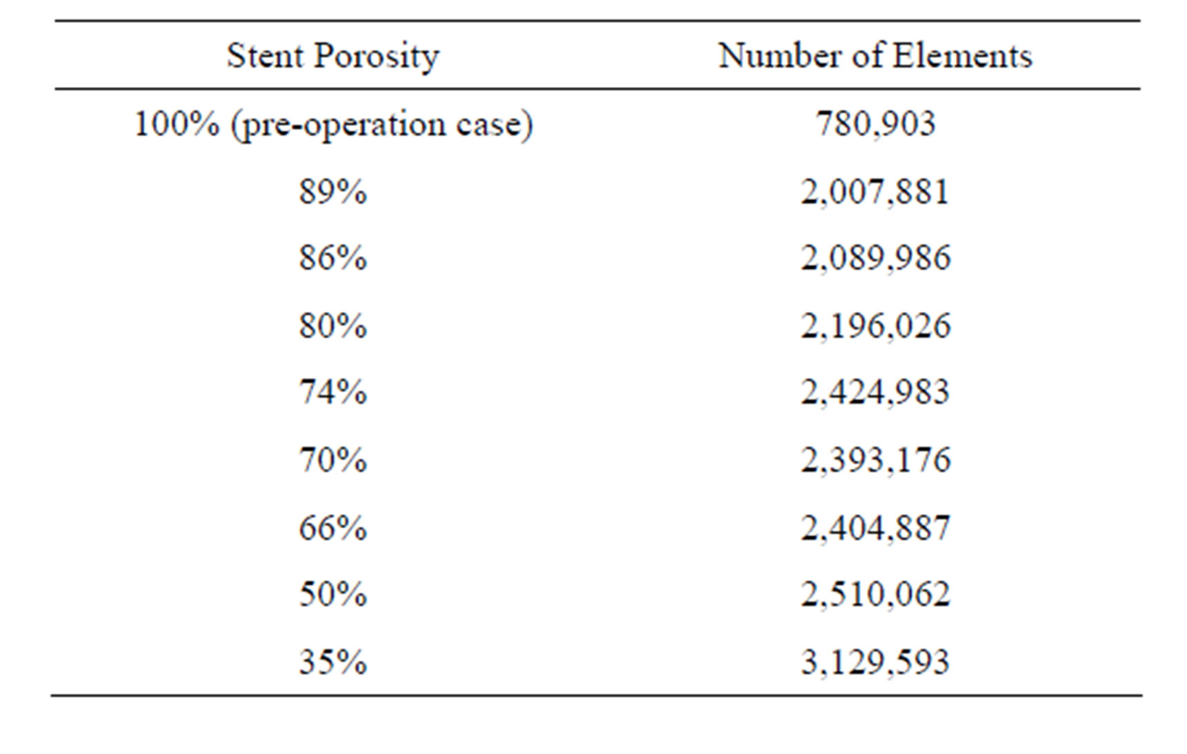
Table 1. Number of elements for various stent porosities.
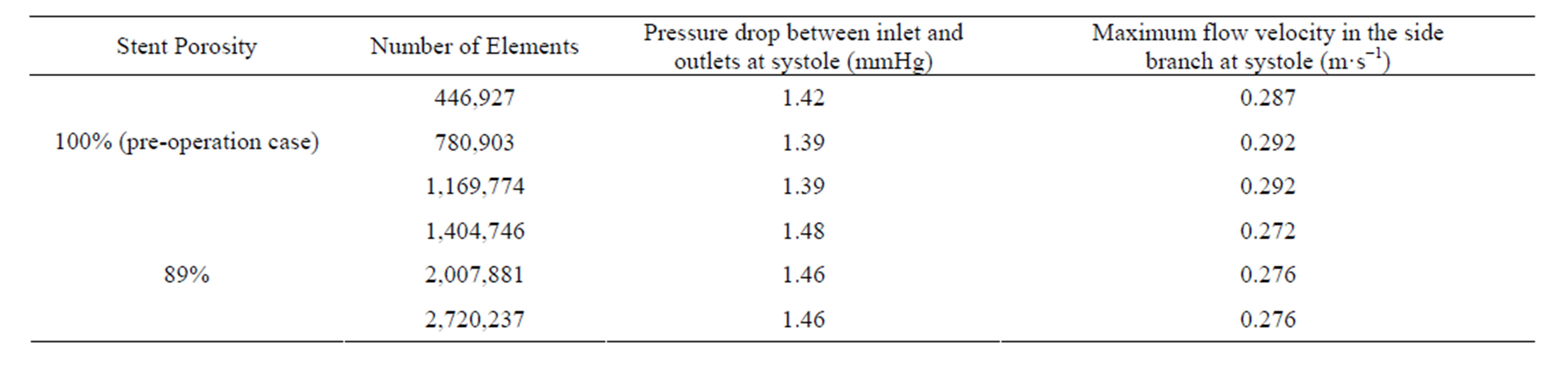
Table 2. Mesh independence tests of the study.
 (a)
(a)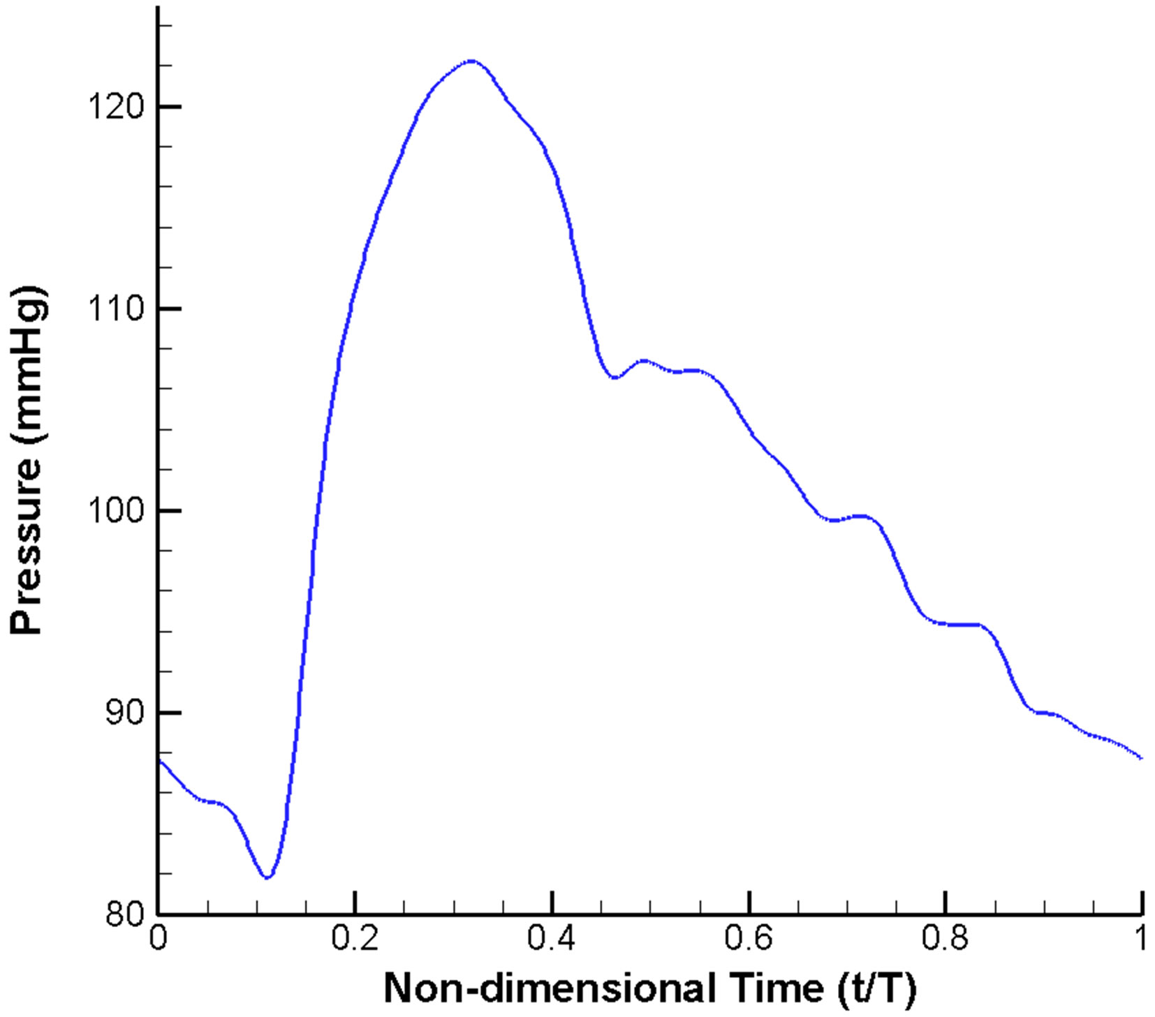 (b)
(b)
Figure 2. Pulsatile blood flow waveform prescribed in the CFD model: (a) Velocity inlet; (b) Pressure outlet.
locity is measured at the outlet of the vessel. For a stent of low porosity, the flow velocity is reduced by up to 50% as compared to the pre-operative situation. Consequently, an extremely low porosity stent might not be desirable as the flow inside the side branch will be dras-
 (a)
(a)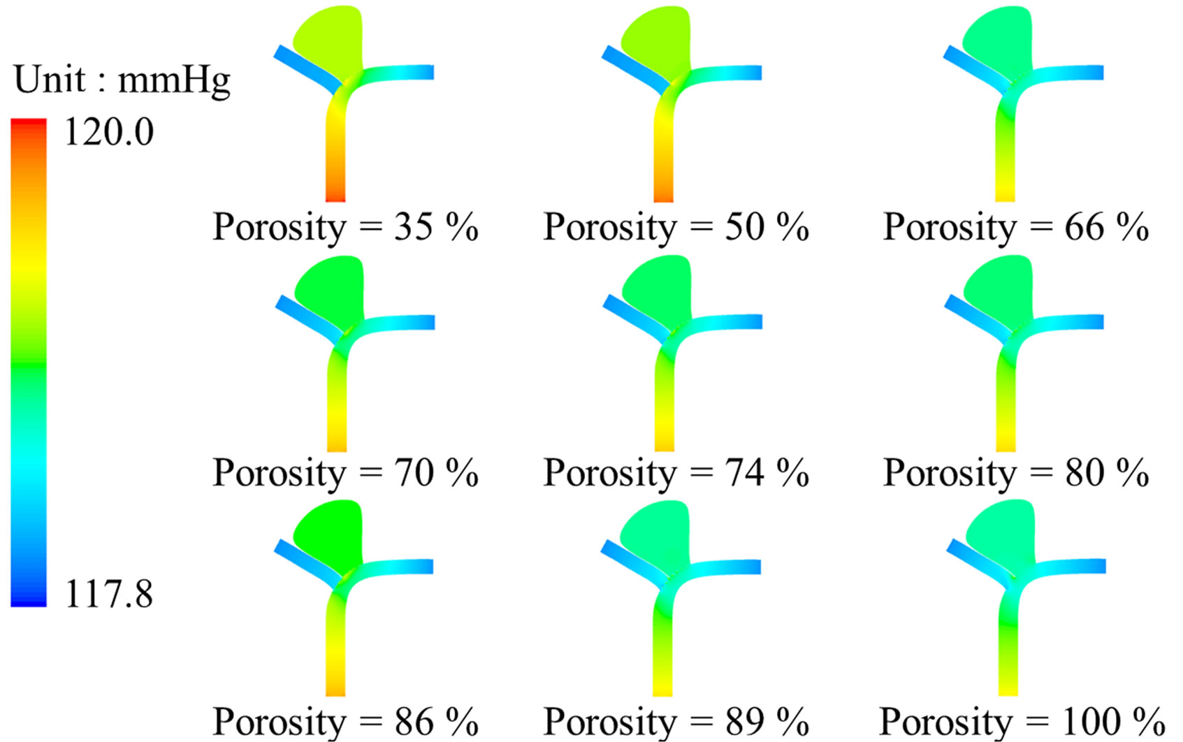 (b)
(b)
Figure 3. Stent porosity significantly modifies flow patterns in the intracranial aneurysm model. Contour maps at peak systole (t/T = 0.25) are shown for: (a) Flow velocity; (b) Intraluminal pressure. As the stent porosity decreases from 100% (nonstented) to 35%, the flow velocity in the side branch was reduced, while the pressure differential decreased inside the aneurysm (see also Figure 4).
tically altered.
Pressure gradient is another critical parameter in determining the flow inside the intracranial aneurysm (Figure 3). The maximum pressure differential within the aneurysm is 19 Pa before stenting. However, this pressure differential drops to the range of 2.9 Pa (porosity = 35%) to 12.1 Pa (porosity = 89%) after stenting (Figure 4(b)). As a greater pressure differential implies a larger tendency for fluid motion, i.e., an insufficient flow reduction
 (a)
(a)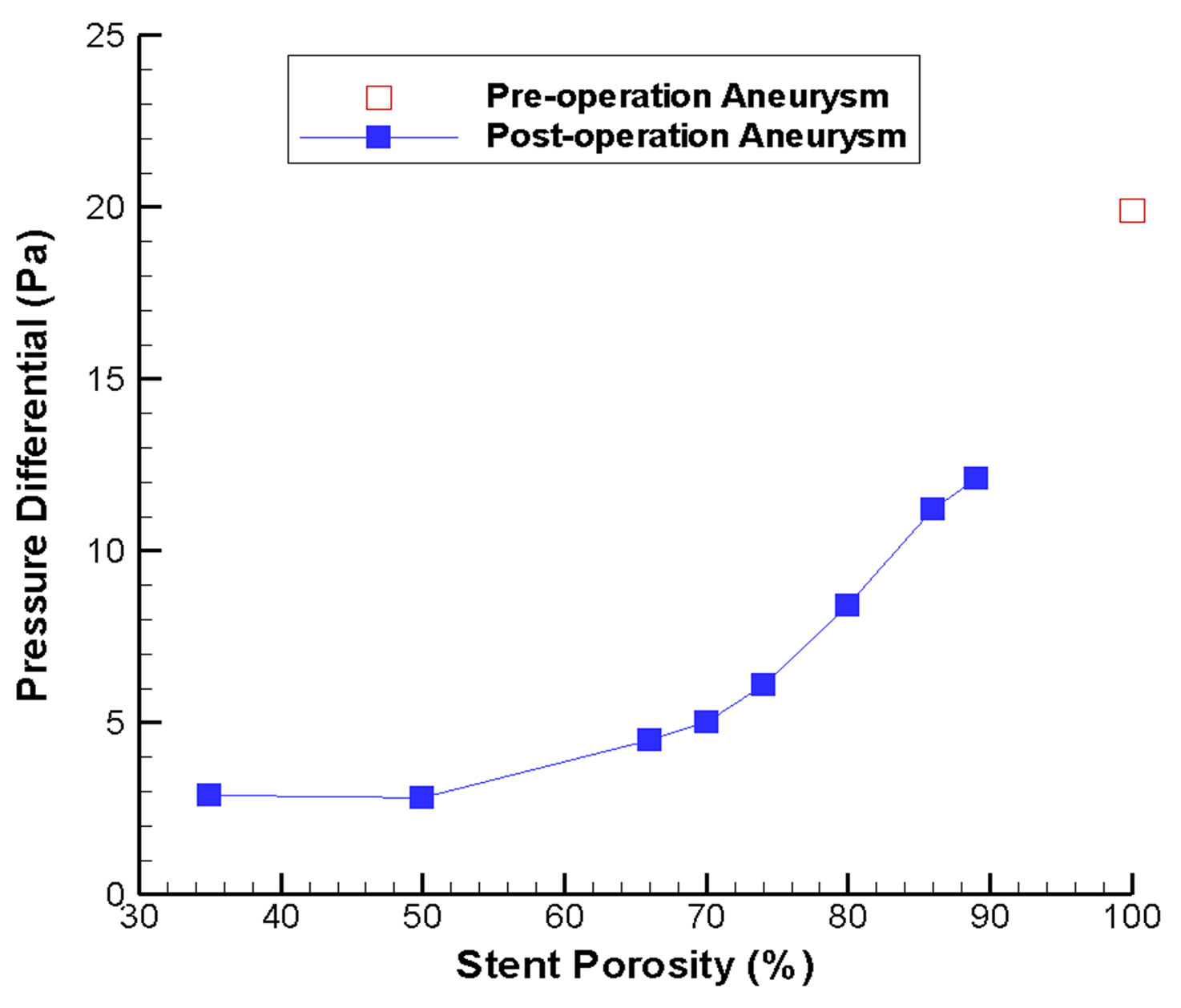 (b)
(b)
Figure 4. Changes in flow velocity and aneurysm pressure as a function of stent porosity. In (a) CFD-derived peak systolic flow velocity values are shown for the side branch vessel and distal parent artery; increasing imbalance between the two branches can be noticed as stent porosity decreases. In (b) the pressure differential inside the aneurysm is plotted; the differential is generally smaller at low stent porosities.
inside the aneurysm, a high porosity stent might not be favorable for endovascular treatment.
The porosity of the stent would also modify the pressure drop between the inlet region (A, Figure 1(a)) and the outlet regions (B, C, Figure 1(a)). Before stent implantation, the pressure drop is relatively small (1.39 mmHg). However, for the post-operation stage, the pressure drop would range from 1.46 mmHg (porosity = 89%) to 1.99 mmHg (porosity = 35%). This indicates that endovascular stenting increases the resistance of blood flow motion into the normal side branch. A stent of very low porosity is even more undesirable, as any reduction in the overall blood pressure due to physiological or pathological changes might hinder blood flow into the normal side branch, thus causing tissue ischemia.
3.2. Wall Shear Stress
The effect of wall shear stress (WSS) in vascular biology had been studied intensively earlier in the literature. Typically, a low WSS would damage the endothelial cells of the vessel wall, perhaps ultimately causing atherosclerosis and plaque formation [38].
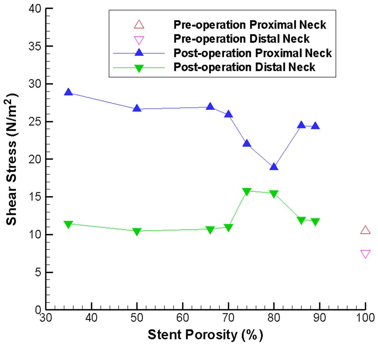
For an unruptured aneurysm, deployment of a metallic stent might alter the WSS on the aneurysm wall, leading to long term damage of the endothelial cells and possibly rupture of the aneurysm. Consequently the WSS at the neck of the aneurysm is analyzed before and after stenting, as the stent is located adjacent to the neck. The variation of WSS at the neck of the aneurysm for different stent porosities is indicated in Figure 5(a). Generally speaking, the maximum shear stress at proximal and distal necks (Figure 1(b)) will increase after stenting, but the shear stress at the distal neck still remains at a relatively low value except for the special porosity range of 75% to 80%.
Consideration of the WSS on the side branch vessel and the distal parent vessel also substantiate our understanding of the flow dynamics (Figure 5(b)). With a stent of low porosity, less fluid can pass through the stent and flow into the side branch. This reduction in flow volume results in a smaller shear stress. This severe reduction of flow might lead to an undesirable hemodynamic environment and adverse pathological consequences. On the other hand, from conservation of mass, the flow along the distal parent vessel must increase, leading to a higher shear stress. Hence careful consideration of rupture risk and follow-up clinical investigation would be recommended.
3.3. Stent Migration Force
An important clinical concern is the risk of stent migration, leading to failure of the endovascular procedure as the neck of the aneurysm would no longer be covered by the metallic stent. This question can be addressed by calculating the shear force per unit area acting on the stent along the flow direction. Based on the simulation results, this value drops almost linearly with the stent porosity, and ranges from 11.55 N·m−2 (porosity = 89%) to 5.33 N·m−2 (porosity = 35%). Consequently, a high porosity stent might pose a greater risk of stent migration, and long term follow-up of the patients are necessary.
3.4. Volume Flow Rates
Flow-diverting stent can minimize the flow rate into the aneurysm, but will also preserve sufficient blood flow in the side branch vessel for the downstream cells and organs. The efficiency of the stent will, however, vary notably with the stent porosity. As the aneurysm is a closed region, the net inflow and outflow must sum to zero algebraically over one cardiac cycle. To measure the mean volume flow rate entering and leaving the aneurysm quantitatively, the integral of the absolute value of the axial velocity (velocity component perpendicular to the neck) is evaluated over a cardiac cycle, moderated by the factor of 1/2, to account for the flow reversal represented only by the absolute value:
 , (3)
, (3)
where Q is the mean volume flow rate (m3·s−1), T is the cardiac cycle (taken as 0.8 second),  is the spatialaveraged absolute axial velocity at the neck region (m·s−1), A is the cross-sectional area of the neck (m2), and t is an arbitrary time instant.
 (a)
(a)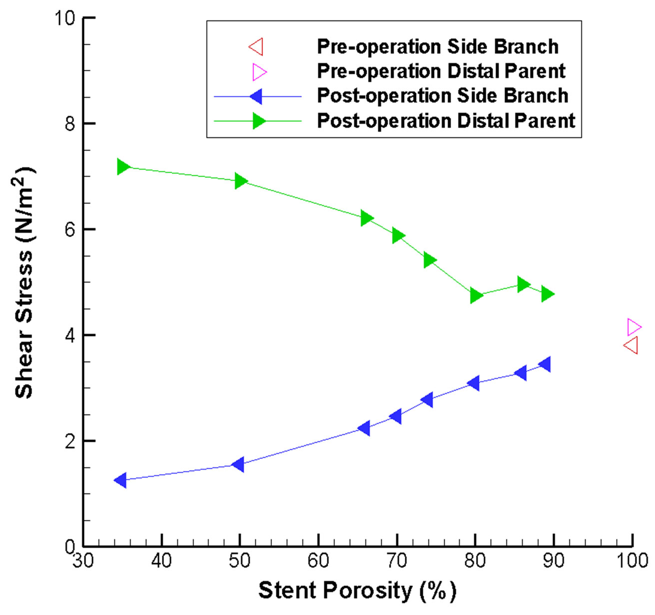 (b)
(b)
Figure 5. Stent porosity affects the maximum wall shear stress at various locations in the intracranial aneurysm model. Results are shown for: (a) Proximal and distal necks of the aneurysm (abnormal variations are evident over the 75% - 80% stent porosity range); (b) Side branch vessel and distal parent artery (difference between the two branches increases as stent porosity drops).
Figure 6 depicts the absolute axial velocity  throughout the cardiac cycle. This absolute axial velocity remains high before the operation, while it would be reduced after stenting, and the reduction depends on the stent porosity. Generally, a high/low porosity stent will have greater/smaller absolute axial velocity. Furthermore, the mean volume flow rates (in ml·s−1; 1 m3·s−1 = 1,000,000 ml·s−1) entering the aneurysm for various stent porosities are shown in Figure 7(a). As the stent porosity becomes smaller, the mean volume flow rate into the aneurysm decreases drastically. However, the curve flattens when the porosity is low, indicating that further reduction in stent porosity by the deployment of multiple stents is unlikely to reduce the flow rate into the aneurysm significantly.
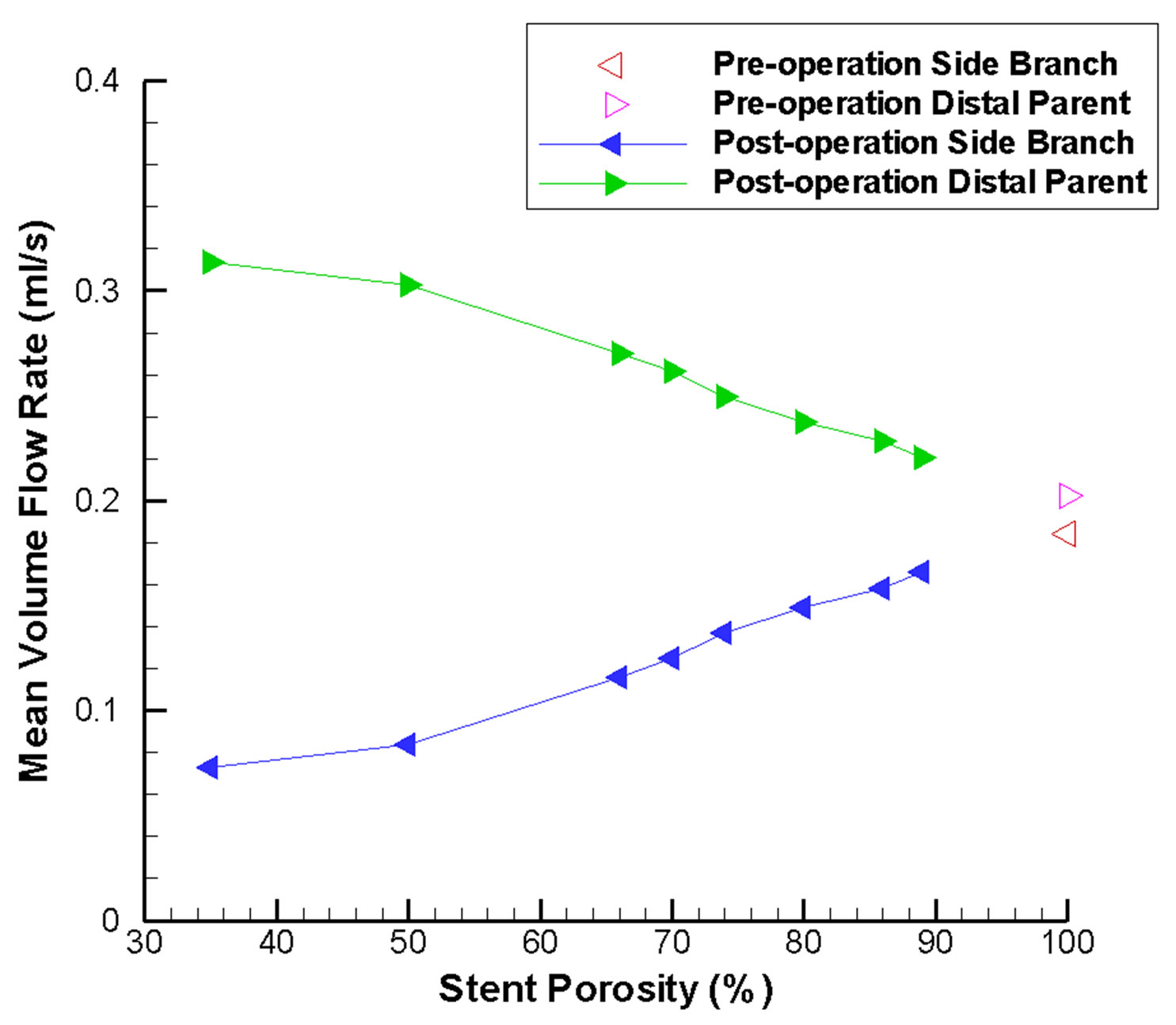
Another issue of clinical interest would be the flow reduction of the side branch vessel nearby. In Figure 7(b), the mean volume flow rates inside the side branch vessel and the distal parent artery are plotted. Due to the presence of the flow-diverting stent, blood is directed to the distal parent artery. This effect becomes more notable as stent porosity decreases, and might lead to occlusion of the side branch vessel.
The percentages of original flow rate inside the aneurysm and the side branch vessel are portrayed in Figure 8. This provides sufficient indication that the optimal stent porosity would fall within a range of 60% to 75%, as the flow rate reduction of the side branch vessel would be lower than that in the aneurysm. This would be the ideal hemodynamic environment, since flow reduction inside the aneurysm might induce flow stasis and thrombosis, while blood flow inside the side branch vessel is preserved for nutrition and oxygen supply to the downstream tissues. This supports the claim that a low porosity stent might cause undesirable outcomes. Conse-
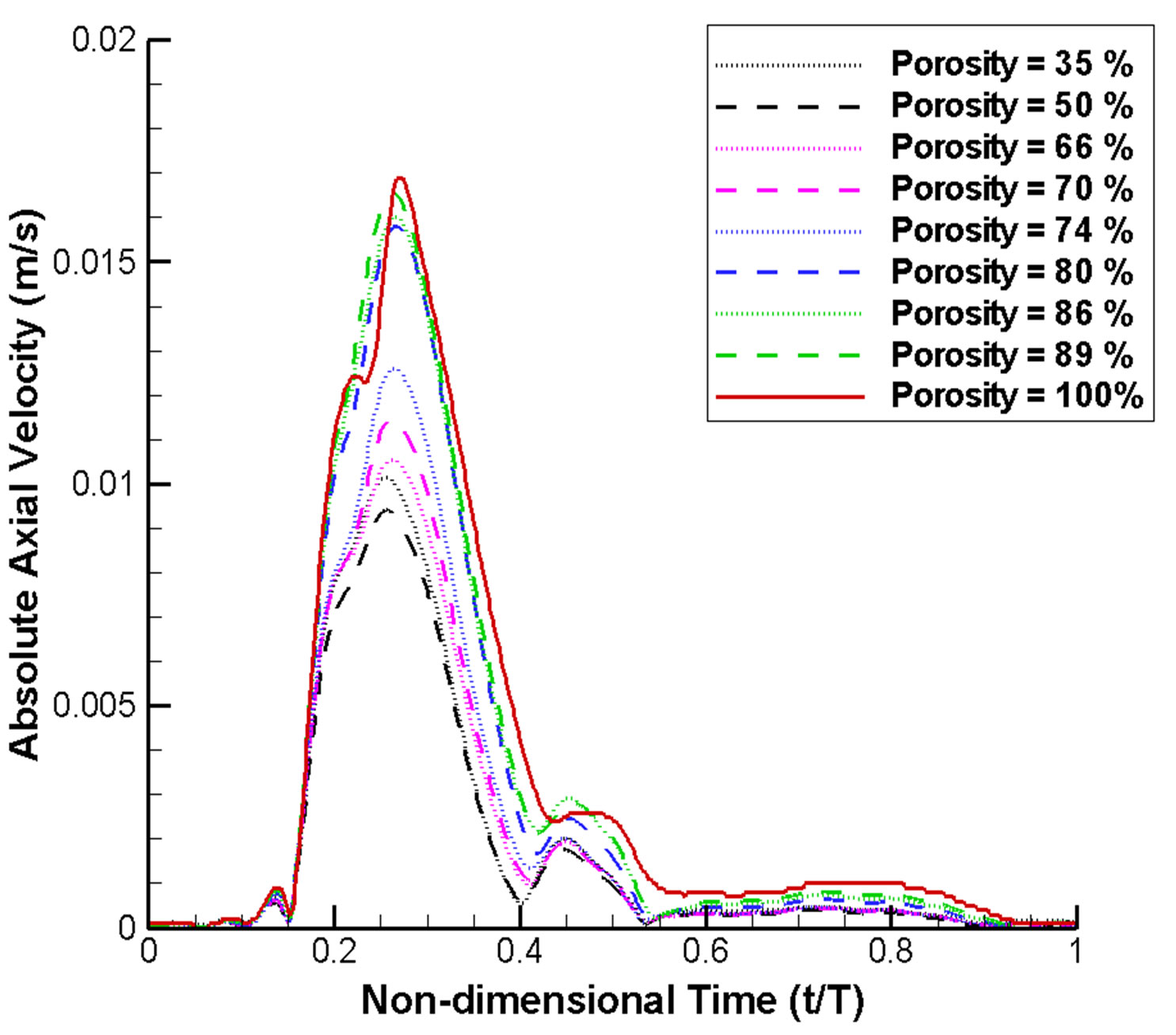
Figure 6. Absolute axial velocity of blood flow at the neck region over a complete cardiac cycle (normalized with respect to cardiac period T). The velocity generally drops as the stent porosity decreases.
 (a)
(a)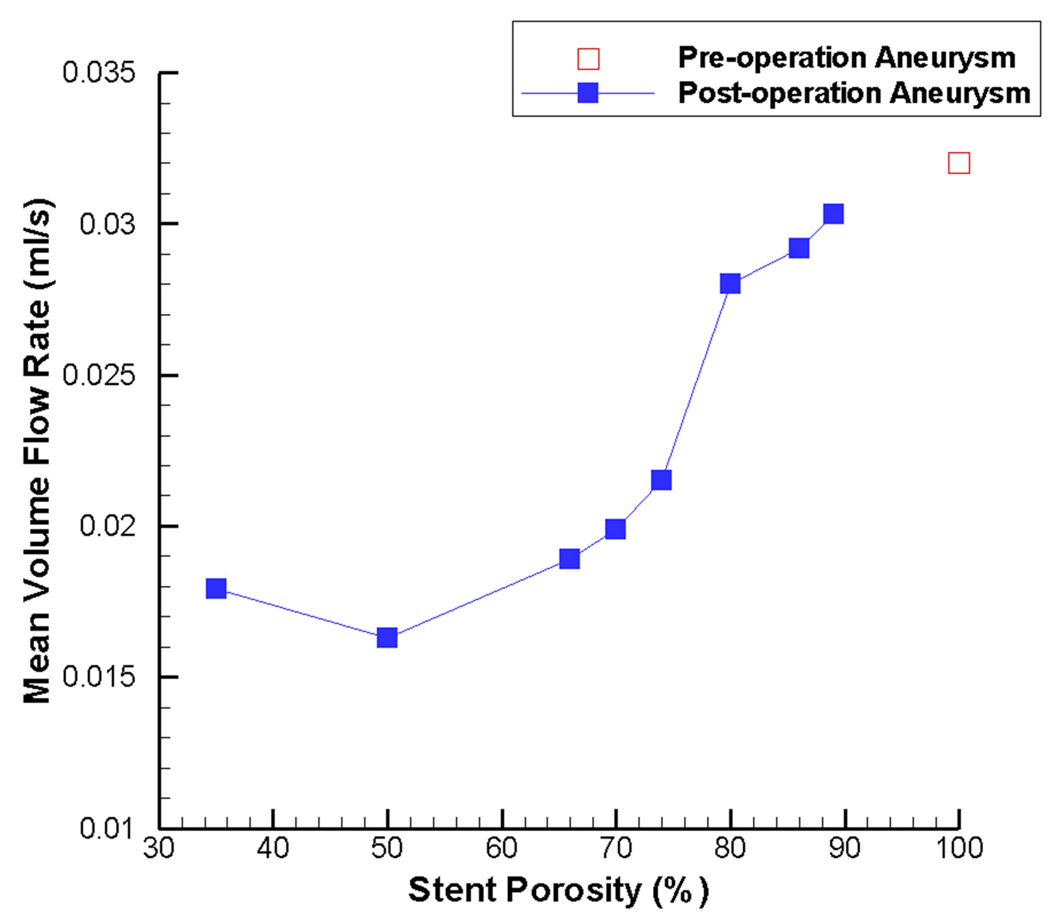 (b)
(b)
Figure 7. Mean volume flow rate variations in the intracranial aneurysm model as a function of stent porosity. (a) CFD-derived values at the aneurysm neck; as stent porosity decreases, significant drop in the flow rate entering the aneurysm can be observed; (b) Corresponding results for the side branch vessel and distal parent artery; at lower stent porosities, mean volume flow rate decreases in the side branch vessel and increases in the distal parent artery.
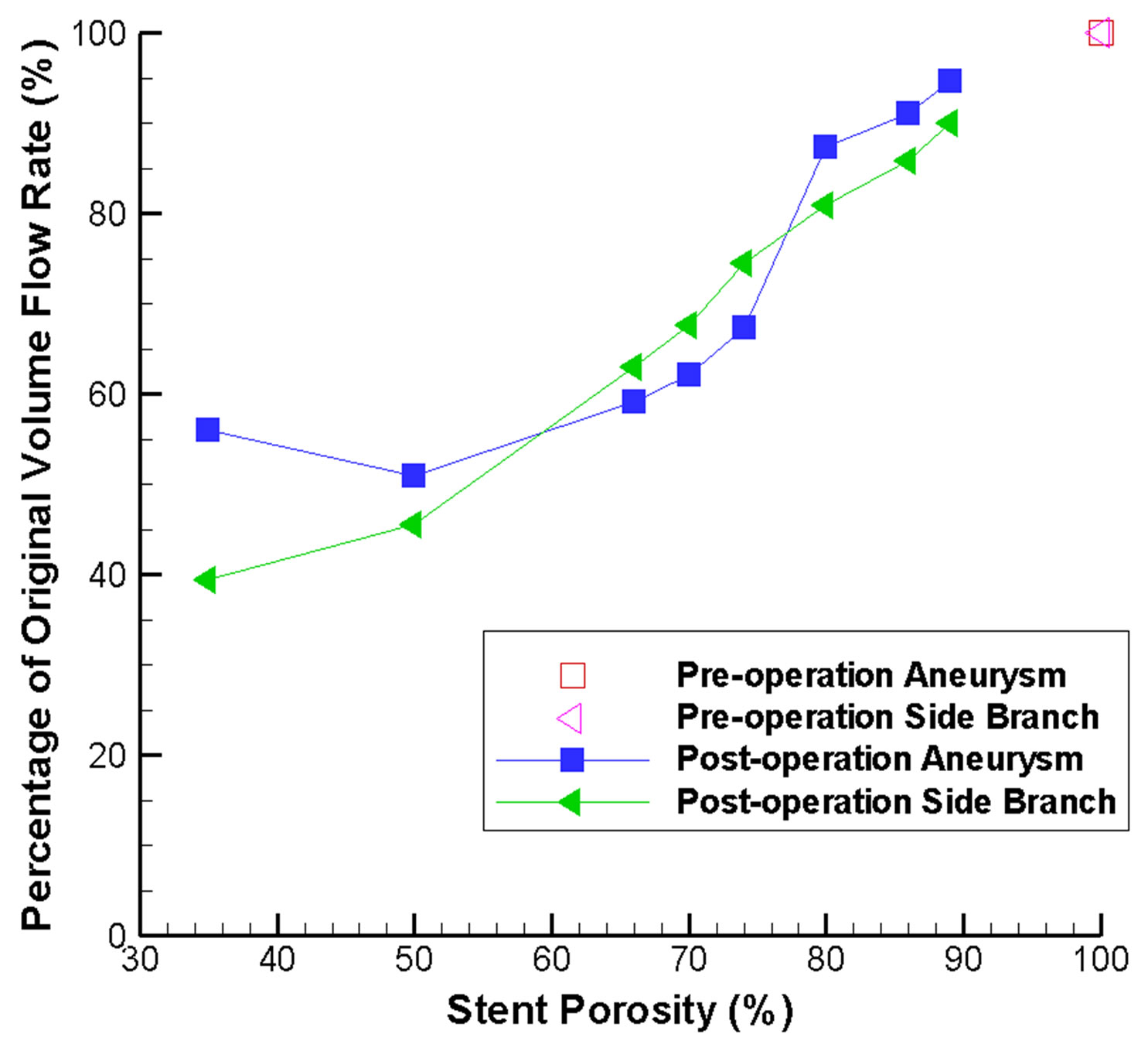
Figure 8. Stent-porosity-dependent flow reduction inside the aneurysm and side branch. Results are shown in terms of percentage of original volume flow rate.
quently, deployment of two or more flow-diverting stents at the same position might not be advisable, and careful follow-up inspection is of vital importance. The results are in fact consistent with those obtained previously in the literature [29]. This quantitative analysis would definitely provide valuable information for making surgical decision and for future endovascular stent design and development.
4. CONCLUSIONS
As diseases of the blood vessels constitute a major cause of mortality and morbidity, many theoretical and experimental methods have been employed to study the human cardiovascular system, e.g. lumped parameter models [56] and magnetic resonance imaging techniques [57]. In this paper we demonstrate that computational continuum mechanics can be profitably utilized too. More precisely, intracranial aneurysms can be treated clinically by implantation of a flow-diverting stent, which is becoming a promising therapeutic modality. By considering an idealized Y-shaped intracranial aneurysm model, the underlying hemodynamics can be determined through computational fluid dynamics studies. The optimal porosity of the stent is examined quantitatively by analyzing the blood flow into the aneurysm and the flow rate inside the side branch vessel. Results from these simulations lead to the conjecture that a flow-diverting stent with porosity in the range of 60% to 75% would be most desirable. Computational results supporting this argument are:
• The maximum flow velocity inside the side branch vessel is vastly reduced by low stent porosity, potentially resulting in insufficient supply of nutrients and oxygen downstream.
• The maximum pressure differential inside the aneurysm still remains high for high stent porosity, which implies that the flow reduction inside the aneurysm is not substantial.
• The pressure drop between the inlet region and the outlet regions will go up substantially for low stent porosity. This will increase the chance of disruption of flow in the healthy side branch or even stroke if blood pressure is not maintained.
• Low wall shear stress (WSS) is believed to cause abnormal endothelial cells functions and other pathological consequences. Here, the maximum shear stress at the proximal and distal necks will generally increase after stenting, but the shear stress at the distal neck still remains at a relatively low regime except for the porosity range of 75% to 80%.
• As the flow inside the side branch vessel is significantly altered by a low porosity stent, the WSS on that vessel is also greatly reduced, potentially increasing the risk of long term damage of the vessel wall.
• The shear force per unit area acting on a high porosity stent is greater, meaning an enhanced risk of stent migration. Consequently, long term follow-up monitoring should be considered.
• Regarding the mean volume flow rate, the flow reduction inside the aneurysm becomes “saturated” when the porosity is low. The flow rate inside the side branch vessel, however, drops drastically with the stent porosity.
The present computational study can certainly provide useful information for clinicians to assess the effect of different stent porosities on the hemodynamics of this therapeutic condition. In clinical practice, deployment of two or more stents at the same position should be considered carefully, as the effective porosity becomes low and might result in adverse consequences.
Finally, remarks are given concerning the limitations in this study. Firstly, although the implantation of the stent would alter the blood flow rate in the side branch, there might be compensatory autoregulation of the cerebral vasculature. This effect, however, is not considered here. Moreover, there is still no clinical evidence to correlate the absolute flow rate reduction of the side branch vessel with tissue ischemia. Furthermore, the present conclusions might be applicable to this particular model only. Consequently, it is worthwhile to test different aneurysm configurations, for example, wide neck aneurysms. Nevertheless, the insight of how porosity of the stent alters the hemodynamics in this pathological condition can still be gained from the present study.
From the perspective of future works, trends predicted by these numerical results may be tested and verified in the laboratory by fabricating intracranial aneurysm phantom models through rapid prototyping. Preferably, these models would be reconstructed from patient-specific imaging data. Flow of blood mimicking fluid can then be quantitatively measured by flow visualization or ultrasonography. Since an elastic soft material will be utilized, further insight including the effects of an elastic vessel wall can be gained. High-frame-rate ultrasound imaging techniques can be employed, which allows almost realtime flow visualization. The deployment of the virtual flow-diverting stent may predict the post-stenting condition before the actual surgical procedure, which provides clinicians with valuable information for treatment planning and subsequent patient care.
5. ACKNOWLEDGEMENTS
Partial financial support has been provided by the Innovation and Technology Commission (ITS/083/11) of the Hong Kong Special Administrative Region Government.
REFERENCES
- Sforza, D.M., Putman, C.M. and Cebral, J.R. (2009) Hemodynamics of cerebral aneurysms. Annual Review of Fluid Mechanics, 41, 91-107. doi:10.1146/annurev.fluid.40.111406.102126
- Humphrey, J.D. and Taylor, C.A. (2008) Intracranial and abdominal aortic aneurysms: Similarities, differences, and need for a new class of computational models. Annual Review of Biomedical Engineering, 10, 221-246. doi:10.1146/annurev.bioeng.10.061807.160439
- Sekhar, L.N. and Heros, R.C. (1981) Origin, growth, and rupture of saccular aneurysms: A review. Neurosurgery, 8, 248-260. doi:10.1227/00006123-198102000-00020
- Schievink, W.I. (1997) Intracranial aneurysms. New England Journal of Medicine, 336, 28-40. doi:10.1056/NEJM199701023360106
- Lasheras, J.C. (2007) The biomechanics of arterial aneurysms. Annual Review of Fluid Mechanics, 39, 293-319. doi:10.1146/annurev.fluid.39.050905.110128
- Perktold, K., Kenner, T., Hilbert, D., Spork, B. and Florian, H. (1988) Numerical blood flow analysis: Arterial bifurcation with a saccular aneurysm. Basic Research in Cardiology, 83, 24-31. doi:10.1007/BF01907101
- Pierot, L. (2011) Flow diverter stents in the treatment of intracranial aneurysms: Where are we? Journal of Neuroradiology, 38, 40-46. doi:10.1016/j.neurad.2010.12.002
- Wanke, I. and Forsting, M. (2008) Stents for intracranial wide-necked aneurysms: More than mechanical protection. Neuroradiology, 50, 991-998. doi:10.1007/s00234-008-0460-0
- Puffer, R.C., Kallmes, D.F., Cloft, H.J. and Lanzino, G. (2012) Patency of the ophthalmic artery after flow diversion treatment of paraclinoid aneurysms. Journal of Neurosurgery, 116, 892-896. doi:10.3171/2011.11.JNS111612
- Cavazzuti, M., Atherton, M., Collins, M. and Barozzi, G. (2010) Beyond the virtual intracranial stenting challenge 2007: Non-newtonian and flow pulsatility effects. Journal of Biomechanics, 43, 2645-2647. doi:10.1016/j.jbiomech.2010.04.042
- Byun, H.S. and Rhee, K. (2004) CFD modeling of blood flow following coil embolization of aneurysms. Medical Engineering & Physics, 26, 755-761. doi:10.1016/j.medengphy.2004.06.008
- Zhao, S., Li, W. and Gu, L. (2012) Biomechanical prediction of abdominal aortic aneurysm rupture risk: Sensitivity analysis. Journal of Biomedical Science and Engineering, 5, 664-671. doi:10.4236/jbise.2012.511083
- Fung, G.S.K., Lam, S.K., Cheng, S.W.K. and Chow, K.W. (2008) On stent-graft models in thoracic aortic endovascular repair: A computational investigation of the hemodynamic factors. Computers in Biology and Medicine, 38, 484-489. doi:10.1016/j.compbiomed.2008.01.012
- Cheng, S.W.K., Lam, E.S.K., Fung, G.S.K., Ho, P., Ting, A.C.W. and Chow, K.W. (2008) A computational fluid dynamic study of stent graft remodeling after endovascular repair of thoracic aortic dissections. Journal of Vascular Surgery, 48, 303-310. doi:10.1016/j.jvs.2008.03.050
- Liou, T.M., Liou, S.N. and Chu, K.L. (2004) Intra-aneurysmal flow with helix and mesh stent placement across side-wall aneurysm pore of a straight parent vessel. ASME Journal of Biomechanical Engineering, 126, 36-43. doi:10.1115/1.1644566
- Seshadhri, S., Janiga, G., Beuing, O., Skalej, M. and Thé- venin, D. (2011) Impact of stents and flow diverters on hemodynamics in idealized aneurysm models. ASME Journal of Biomechanical Engineering, 133, 071005-1-9. doi:10.1115/1.4004410
- Shobayashi, Y., Tanoue, T., Tateshima, S. and Tanishita, K. (2010) Mechanical design of an intracranial stent for treating cerebral aneurysms. Medical Engineering & Physics, 32, 1015-1024. doi:10.1016/j.medengphy.2010.07.002
- Babiker, M.H., Gonzalez, L.F., Ryan, J., Albuquerque, F., Collins, D., Elvikis, A. and Frakes, D.H. (2012) Influence of stent configuration on cerebral aneurysm fluid dynamics. Journal of Biomechanics, 45, 440-447. doi:10.1016/j.jbiomech.2011.12.016
- Bernardini, A., Larrabide, I., Morales, H.G., Pennati, G., Petrini, L., Cito, S. and Frangi, A.F. (2011) Influence of different computational approaches for stent deployment on cerebral aneurysm haemodynamics. Interface Focus, 1, 338-348. doi:10.1098/rsfs.2011.0004
- Bernardini, A., Larrabide, I., Petrini, L., Pennati, G., Flore, E., Kim, M. and Frangi, A.F. (2012) Deployment of self-expandable stents in aneurysmatic cerebral vessels: Comparison of different computational approaches for interventional planning. Computer Methods in Biomechanics and Biomedical Engineering, 15, 303-311. doi:10.1080/10255842.2010.527838
- Meng, H., Wang, Z., Kim, M., Ecker, R.D. and Hopkins, L.N. (2006) Saccular aneurysms on straight and curved vessels are subject to different hemodynamics: Implications of intravascular stenting. American Journal of Neuroradiology, 27, 1861-1865.
- Ford, M.D., Lee, S.W., Lownie, S.P., Holdsworth, D.W. and Steinman, D.A. (2008) On the effect of parent-aneurysm angle on flow patterns in basilar tip aneurysms: Towards a surrogate geometric marker of intra-aneurismal hemodynamics. Journal of Biomechanics, 41, 241- 248. doi:10.1016/j.jbiomech.2007.09.032
- Sato, K., Imai, Y., Ishikawa, T., Matsuki, N. and Yamaguchi, T. (2008) The importance of parent artery geometry in intra-aneurysmal hemodynamics. Medical Engineering & Physics, 30, 774-782. doi:10.1016/j.medengphy.2007.09.006
- Valen-Sendstad, K., Mardal, K.A. and Steinman, D.A. (2013) High-resolution CFD detects high-frequency velocity fluctuations in bifurcation, but not sidewall, aneurysms. Journal of Biomechanics, 46, 402-407. doi:10.1016/j.jbiomech.2012.10.042
- Yu, S.C.M. and Zhao, J.B. (1999) A steady flow analysis on the stented and non-stented sidewall aneurysm models. Medical Engineering & Physics, 21, 133-141. doi:10.1016/S1350-4533(99)00037-5
- Rhee, K., Han, M.H. and Cha, S.H. (2002) Changes of flow characteristics by stenting in aneurysm models: Influence of aneurysm geometry and stent porosity. Annals of Biomedical Engineering, 30, 894-904. doi:10.1114/1.1500406
- Lieber, B.B., Stancampiano, A.P. and Wakhloo, A.K. (1997) Alteration of hemodynamics in aneurysm models by stenting: Influence of stent porosity. Annals of Biomedical Engineering, 25, 460-469. doi:10.1007/BF02684187
- Augsburger, L., Farhat, M., Reymond, P., Fonck, E., Kulcsar, Z., Stergiopulos, N. and Rüfenacht, D.A. (2009) Effect of flow diverter porosity on intraaneurysmal blood flow. Clinical Neuroradiology, 19, 204-214. doi:10.1007/s00062-009-9005-0
- Liou, T.M. and Li, Y.C. (2008) Effects of stent porosity on hemodynamics in a sidewall aneurysm model. Journal of Biomechanics, 41, 1174-1183. doi:10.1016/j.jbiomech.2008.01.025
- Kim, M., Levy, E.I., Meng, H. and Hopkins, L.N. (2007) Quantification of hemodynamic changes induced by virtual placement of multiple stents across a wide-necked basilar trunk aneurysm. Neurosurgery, 61, 1305-1313. doi:10.1227/01.neu.0000306110.55174.30
- Janiga, G., Rössl, C., Skalej, M. and Thévenin, D. (2013) Realistic virtual intracranial stenting and computational fluid dynamics for treatment analysis. Journal of Biomechanics, 46, 7-12. doi:10.1016/j.jbiomech.2012.08.047
- Sadasivan, C., Cesar, L., Seong, J., Rakian, A., Hao, Q., Tio, F.O., Wakhloo, A.K. and Lieber, B.B. (2009) An original flow diversion device for the treatment of intracranial aneurysms: Evaluation in the rabbit elastase-induced model. Stroke, 40, 952-958. doi:10.1161/STROKEAHA.108.533760
- Szikora, I., Berentei, Z., Kulcsar, Z., Marosfoi, M., Vajda, Z.S., Lee, W., Berez, A. and Nelson, P.K. (2010) Treatment of intracranial aneurysms by functional reconstruction of the parent artery: The Budapest experience with the Pipeline Embolization Device. American Journal of Neuroradiology, 31, 1139-1147. doi:10.3174/ajnr.A2023
- Tähtinen, O.I., Manninen, H.I., Vanninen, R.L., Seppä- nen, J., Niskakangas, T., Rinne, J. and Keski-Nisula, L. (2012) The silk flow-diverting stent in the endovascular treatment of complex intracranial aneurysms: Technical aspects and midterm results in 24 consecutive patients. Neurosurgery, 70, 617-624. doi:10.1227/NEU.0b013e31823387d4
- Kim, M., Taulbee, D.B., Tremmel, M. and Meng, H. (2008) Comparison of two stents in modifying cerebral aneurysm hemodynamics. Annals of Biomedical Engineering, 36, 726-741. doi:10.1007/s10439-008-9449-4
- Benndorf, G., Herbon, U., Sollmann, W.P. and Campi, A. (2001) Treatment of a ruptured dissecting vertebral artery aneurysm with double stent placement: Case report. American Journal of Neuroradiology, 22, 1844-1848.
- Cekirge, H.S., Yavuz, K., Geyik, S. and Saatci, I. (2011) A novel “Y” stent flow diversion technique for the endovascular treatment of bifurcation aneurysms without endosaccular coiling. American Journal of Neuroradiology, 32, 1262-1268. doi:10.3174/ajnr.A2475
- Malek, A.M., Alper, S.L. and Izumo, S. (1999) Hemodynamic shear stress and its role in atherosclerosis. Journal of the American Medical Association, 282, 2035-2042. doi:10.1001/jama.282.21.2035
- Shojima, M., Oshima, M., Takagi, K., Torii, R., Hayakawa, M., Katada, K., Morita, A. and Kirino, T. (2004) Magnitude and role of wall shear stress on cerebral aneurysm: Computational fluid dynamic study of 20 middle cerebral artery aneurysms. Stroke, 35, 2500-2505. doi:10.1161/01.STR.0000144648.89172.0f
- Boussel, L., Rayz, V., McCulloch, C., Martin, A., Acevedo-Bolton, G., Lawton, M., Higashida, R., Smith, W.S., Young, W.L. and Saloner, D. (2008) Aneurysm growth occurs at region of low wall shear stress: Patient-specific correlation of hemodynamics and growth in a longitudinal study. Stroke, 39, 2997-3002. doi:10.1161/STROKEAHA.108.521617
- Jou, L.D. and Mawad, M.E. (2011) Hemodynamic effect of Neuroform stent on intimal hyperplasia and thrombus formation in a carotid aneurysm. Medical Engineering & Physics, 33, 573-580. doi:10.1016/j.medengphy.2010.12.013
- Kelly, M.E., Turner IV, R.D., Moskowitz, S.I., Gonugunta, V., Hussain, M.S. and Fiorella, D. (2008) Delayed migration of a self-expanding intracranial microstent. American Journal of Neuroradiology, 29, 1959-1960. doi:10.3174/ajnr.A1224
- Lobotesis, K., Gholkar, A. and Jayakrishnan, V. (2010) Early migration of a self expanding intracranial stent: Case report. Neurosurgery, 67, E516-E517. doi:10.1227/01.NEU.0000372094.75062.D4
- Ujiie, H., Tamano, Y., Sasaki, K. and Hori, T. (2001) Is the aspect ratio a reliable index for predicting the rupture of a saccular aneurysm? Neurosurgery, 48, 495-503. doi:10.1097/00006123-200103000-00007
- Nader-Sepahi, A., Casimiro, M., Sen, J. and Kitchen, N.D. (2004) Is aspect ratio a reliable predictor of intracranial aneurysm rupture? Neurosurgery, 54, 1343-1348. doi:10.1227/01.NEU.0000124482.03676.8B
- Tang, A.Y.S., Lai, S.K., Leung, K.M., Leung, G.K.K. and Chow, K.W. (2012) Influence of the aspect ratio on the endovascular treatment of intracranial aneurysms: A computational investigation. Journal of Biomedical Science and Engineering, 5, 422-431. doi:10.4236/jbise.2012.58054
- Tanemura, H., Ishida, F., Miura, Y., Umeda, Y., Fukazawa, K., Suzuki, H., Sakaida, H., Matsushima, S., Shimosaka, S. and Taki, W. (2013) Changes in hemodynamics after placing intracranial stents. Neurologia MedicoChirurgica, 53, 171-178. doi:10.2176/nmc.53.171
- Marzo, A., Singh, P., Larrabide, I., Radaelli, A., Coley, S., Gwilliam, M., Wilkinson, I.D., Lawford, P., Reymond, P., Patel, U., Frangi, A. and Hose, D.R. (2011) Computational hemodynamics in cerebral aneurysms: The effects of modeled versus measured boundary conditions. Annals of Biomedical Engineering, 39, 884-896. doi:10.1007/s10439-010-0187-z
- Fan, Y., Cheng, S.W.K., Qing, K.X. and Chow, K.W. (2010) Endovascular repair of type B aortic dissection: A study by computational fluid dynamics. Journal of Biomedical Science and Engineering, 3, 900-907. doi:10.4236/jbise.2010.39120
- Ku, D.N. (1997) Blood flow in arteries. Annual Review of Fluid Mechanics, 29, 399-434. doi:10.1146/annurev.fluid.29.1.399
- Reymond, P., Merenda, F., Perren, F., Rüfenacht, D. and Stergiopulos, N. (2009) Validation of a one-dimensional model of the systemic arterial tree. American Journal of Physiology—Heart and Circulatory Physiology, 297, H208-H222. doi:10.1152/ajpheart.00037.2009
- Hajjar, I., Selim, M., Novak, P. and Novak, V. (2007) The relationship between nighttime dipping in blood pressure and cerebral hemodynamics in nonstroke patients. The Journal of Clinical Hypertension, 9, 929-936. doi:10.1111/j.1524-6175.2007.07342.x
- Steinman, D.A., Milner, J.S., Norley, C.J., Lownie, S.P. and Holdsworth, D.W. (2003) Image-based computational simulation of flow dynamics in a giant intracranial aneurysm. American Journal of Neuroradiology, 24, 559- 566.
- Isoda, H., Hirano, M., Takeda, H., Kosugi, T., Alley, M.T., Markl, M., Pelc, N.J. and Sakahara, H. (2006) Visualization of hemodynamics in a silicon aneurysm model using time-resolved, 3D, phase-contrast MRI. American Journal of Neuroradiology, 27, 1119-1122.
- Stuhne, G.R. and Steinman, D.A. (2004) Finite-element modeling of the hemodynamics of stented aneurysms. ASME Journal of Biomechanical Engineering, 126, 382- 387. doi:10.1115/1.1762900
- Kokalari, I., Karaja, T. and Guerrisi, M. (2013) Review on lumped parameter method for modeling the blood flow in systemic arteries. Journal of Biomedical Science and Engineering, 6, 92-99. doi:10.4236/jbise.2013.61012
- Martins, H., Carreiras, M., Ribeiro, M.M., Sousa, P. and Silva-Fortes, C. (2013) The influence of the blood pressure on the venous cerebral flow measured by magnetic susceptibility (SWI) technique. Journal of Biomedical Science and Engineering, 6, 426-434. doi:10.4236/jbise.2013.63A053