Engineering
Vol.6 No.4(2014), Article ID:44050,8 pages DOI:10.4236/eng.2014.64024
A Study on the Characteristics and the Effective Reduction Methods for the Ground Vibration Due to the Travelling Tilting Train
Hee Seok Kim
Structural Engineering Research Division, Korea Institute of Construction Technology, Goyang-Si, Republic of Korea
Email: lagoon@kict.re.kr
Copyright © 2014 by author and Scientific Research Publishing Inc.
This work is licensed under the Creative Commons Attribution International License (CC BY).
http://creativecommons.org/licenses/by/4.0/


Received 3 February 2014; revised 3 March 2014; accepted 10 March 2014
ABSTRACT
In this paper, a study on the characteristics and the reduction methods of ground vibration due to the tilting train travelling in the conventional line is carried out. The load transmitted into the ground is computed considering the interaction between the tilting car and the line. This load is then applied in the numerical model for the analysis of ground vibration due to the travelling tilting car. The far-fields of the numerical model are modeled using the dashpot, as one of the most widely used absorbing boundaries in finite element analysis. Using this numerical model, the analysis of the ground vibration characteristics caused by the travelling tilting car and the analysis of the blocking effect of the ground vibration by wave barriers are performed. From the numerical analysis, it is shown that the blocking effect of the trench and the barrier filled with soft material is more effective than that of the barrier filled with hard material.
Keywords:Component; Ground Vibration; Tilting Car; Absorbing Boundary; Wave Barrier

1. Introduction
The Gyeongbu High Speed Railway in Korea significantly increased the speed of the national railway network in a will to reduce the transportation cost of goods and boost the national competitiveness. However, its construction required tremendous cost and time. Besides, the development of the semi high speed/high speed tilting train together with the reshuffling of the alignment to improve the speed while using the existing line to make it possible to exploit the established infrastructure. This new option can thus contribute to solving the economic burden and enhancing the transportation means of areas that did not share the benefits of the high speed railway like the Jungang Line, Yeongdong Line and Taebaek Line in Korea. Improving the speed by reshuffling the alignment can be achieved by adopting an appropriate cant to prevent the overturning of the vehicle or the loss of riding comfort caused by the centrifugal force in the curved section or by flattening the curve to make it practically straight but such solutions are not only expensive but their applicability is also very limited due to the topographical conditions at hand. Following, adequate solutions should be conceived for the train rather than for the track. The development of the tilting train may constitute such solution with significantly reduced cost while providing a degree of comfort comparable to the high speed train by tilting the track inward in the curved section as a pendulum so as to offer riding stability and comfort to the passenger.
However, the replacement of the existing train running currently at maximum operating speed of 130 km/h by the tilting train traveling at speed beyond 200 km/h will change the operating environment. This stresses the necessity to implement performance evaluation of the existing track crossed by the tilting train including the examination of the wheel force and lateral force on the track, the safety and the riding stability in curved section. In addition, the dynamic behavior caused by the interaction between the train and the track as well as the environmental vibrations along the railway should also be evaluated to secure the safety of the train and riding comfort.
There is thus a serious need in investigating thoroughly the vibration mechanism induced by the interaction between the rail and wheel of the tilting train that will run at high speed on the existing track structure and the characteristics of the ground vibration transmitted to the neighboring structures through the ground during the crossing of the train. Accordingly, this study intends to examine the characteristics of ground vibration caused by the travelling of the tilting train, and suggests methods for reducing the ground vibration.
The load transmitted to the ground during the traveling of the train is computed by means of the dynamic model analysis of the track and train considering the traveling characteristics of the tilting train. The results of the analysis are then used to identify the loading mechanism and its characteristics. The infinite ground is modeled by numerical element domains by adopting absorbing boundaries using viscous dampers. The computed transferred load is applied to the numerical model to perform numerical analysis. And the blocking effect of the ground vibration by wave barriers is analyzed through the numerical analysis.
2. Transferred Load and Propagation Characteristics of Ground Vibration Due to Travelling Train
When the train crosses a straight section, the leftand right-side wheel loads have identical size and are transferred to the ground through the rails. However, in a curved section, the leftand right-side wheel loads have different sizes because of the centrifugal force and the tilting of the train due to the adjusting cant and are transferred to the ground through the rails. Especially, in the case of the tilting train crossing the curved section at higher speed than conventional trains, the developed wheel loads present a pattern different to that of conventional trains due to the difference in the dimensions of the train accompanied with the increase of the centrifugal force and the additional tilting brought by the tilt angle. Accordingly, since the characteristics of the vibration propagating to the ground may also differ, the traveling characteristics of the tilting train must imperatively be reflected in the ground vibration analysis.
This study computes the size of the wheel loads considering the dimensions of the tilting train, the centrifugal force and the tilt angle so as to calculate the load transferred to the ground during the crossing of a curved section.
Figure 1 compares the PSD of the force transferred to the sleeper by the conventional train and tilting train according to the running speed in a straight section. Here, the peaks occur at various frequencies due to the crossing period of the diverse wheels. It can be also observed that the high frequency contents increase with higher speed. The maximum loads for all the running speeds occur at frequencies below 20 Hz. In addition, the transferred load caused by the tilting train appears to be larger than that of the conventional train. This can be simply explained by the difference in the dimensions of the trains, which result in the occurrence of a larger transferred load induced by the tilting train for the same speed in a straight section [1] .
When the train travels in a curved section, asymmetric wheel loads occur due to the adjusting cant and the centrifugal force. Especially, the tilting train exhibits wheel loading with a pattern different to the conventional train because of the dimensions of the train and the differences in the tilt angle and centrifugal force [2] [3] .
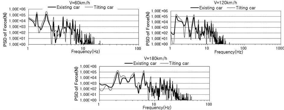
Figure 1. PSD of transferred load according to traveling speed of train (sleeper) [1] .
Since the pattern of the vibration propagation can also vary, numerical analysis is performed considering the riding characteristics in a curved section and the loads of Figure 1.
Figures 2 and 3 plot the frequency contents of the displacements and Figures 4 and 5 plot the frequency contents of the accelerations per running speed (turning radius) according to the distance from the vibration source. The frequencies are seen to shift toward high frequency band with higher speed because of the characteristics of the load occurrence in Figure 1. Moreover, for identical speeds, the displacements and accelerations at the receiving probe appear to occur identical frequency bands. This last result can be explained by the fact that the shear wave propagates without mode conversion.
3. Ground Vibration Reduction by Anti-Vibration Structures
Evaluating the vibrations around the railway in terms of the response of the track and the environmental vibrations is important for the safety and travelling comfort of the train. The popularization and acceleration of the speed of the railway require to perform field monitoring and qualitative analysis in order to provide adequate vibration-reduction measures. The measures reducing the noisy vibrations occurring in the train can be divided into 3 domains that are, the vibration source, propagation path and, vibrating part.
Among them, the anti-vibration measures related to the vibration source of the track structure are the most efficient not only in terms of the establishment of regulatory anti-vibration measures of the vibration source but also in terms of effectiveness and economy. This efficiency can be explained by the fact that the characteristics of the vibration caused by the train as well as the characteristics of the structure and ground vibration transmitted below the track are fundamentally and extremely affected by the track structure. However, the suppression of vibration at the source is more effective for reducing the high frequency vibrations caused by the roughness load than the low frequency vibrations caused by the moving wheel load [4] .
Following, this approach is more suited for suppressing the vibration of track structures installed on bridges or other structures rather than suppressing the vibration of the track structure installed on the ground since the vibration propagating to the ground experiences relatively faster damping of its high frequency content making the ground vibration more governed by the low frequency vibration generated by the moving wheel load. Accordingly, the anti-vibration measures of the vibration path may be more effective than the anti-vibration measures of the vibration source for the track structure installed on the ground. Consequently, this study examines the vibration-blocking effect provided by the trench and wave barrier among the anti-vibration methods of the vibration path.
3.1. Vibration-Blocking by Trench
Numerical analysis is performed to examine the ground vibration-reduction effect provided by the trench. The travelling model of the tilting train in a curved section (R = 1200 m) is selected as example. The analysis is conducted by varying the depth of the trench (D = 10, 28, 50 m) and its distance from the vibration source (L =
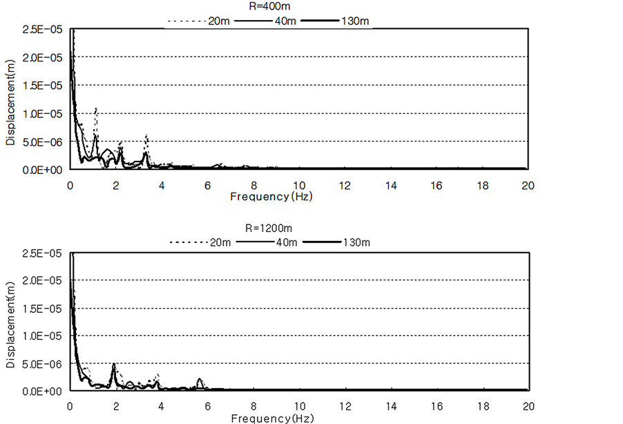
Figure 2. Frequency content of displacement of conventional train.
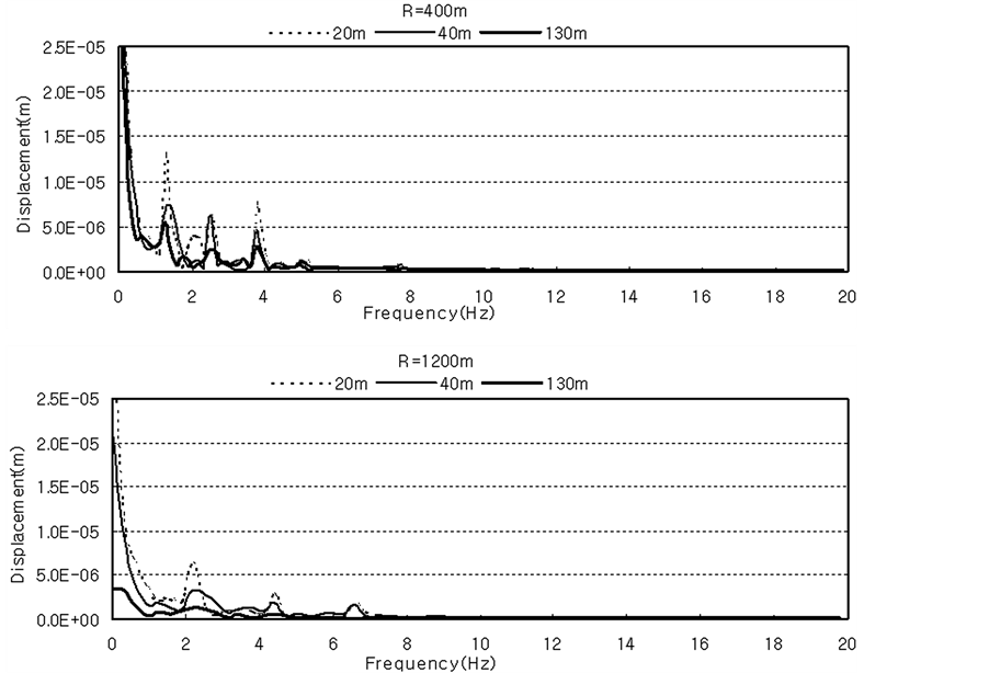
Figure 3. Frequency content of displacement of tilting train.
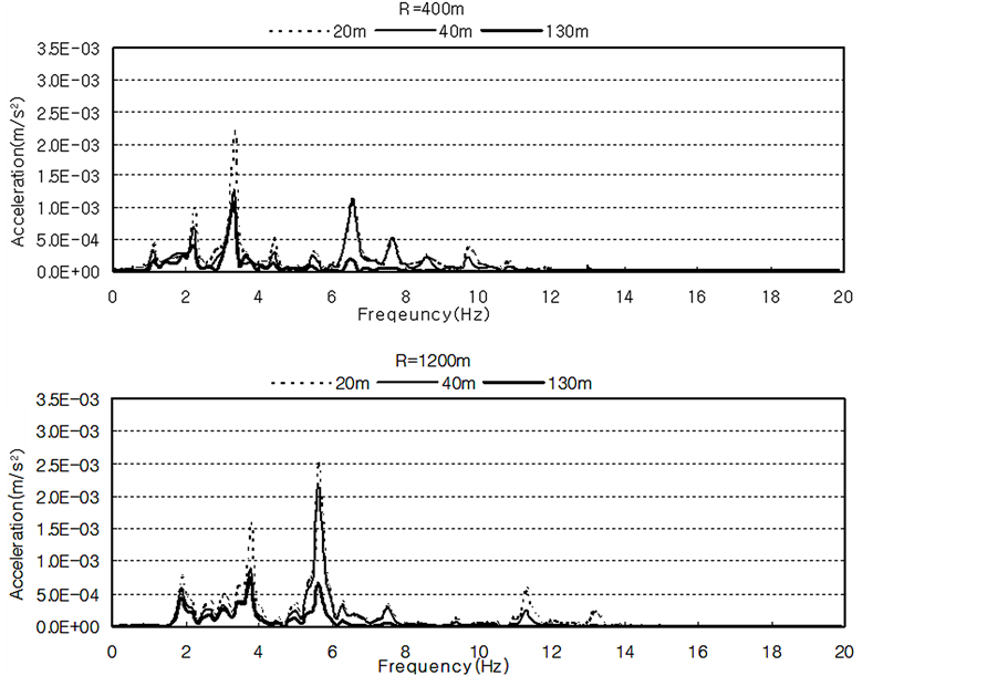
Figure 4. Frequency content of acceleration of conventional train.
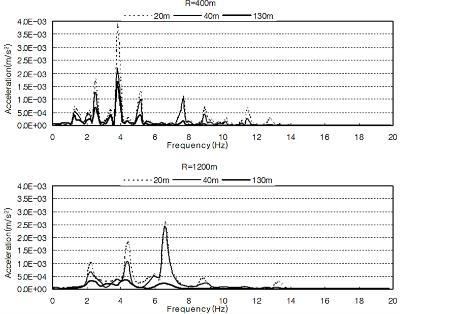
Figure 5. Frequency content of acceleration of tilting train.
20, 46, 80 m) considering the frequency contents shown in Figures 2-5 according to the travelling tilting train in the curved section [1] .
Figures 6 and 7 present respectively the reduction ratios of the amplitudes of the displacement and acceleration per trench depth (D) with respect to the position (L) of the trench. After the installation of the trench, the displacement shows a transmissivity of about 40% to 80% according to the distance (bar in the graphs) whereas it is about 10% to 40% for the acceleration. The difference in the transmissivity between the displacement and the acceleration is related to the frequency developed during the travelling of the tilting train. In other words, this difference can be explained by the lower frequency developed for the maximum displacement amplitude than that developed for the maximum acceleration amplitude in the frequency content during the crossing of the tilting train [1] . Following, for a trench with identical condition, larger reduction of the amplitude is achieved for the acceleration.
In Figure 7, for positions L = 46 m and 80 m of the trench, that is posterior to one wavelength of the surface wave (2 Hz), the trench depths of 28 m and 50 m exhibit similar transmissivity (20%) whereas the trench with depth of 10 m shows relatively larger transmissivity (40%). This can be explained by the fact that the maximum amplitude frequency of the acceleration lies around 6.5 Hz together with 2 Hz content as observed in the fre-
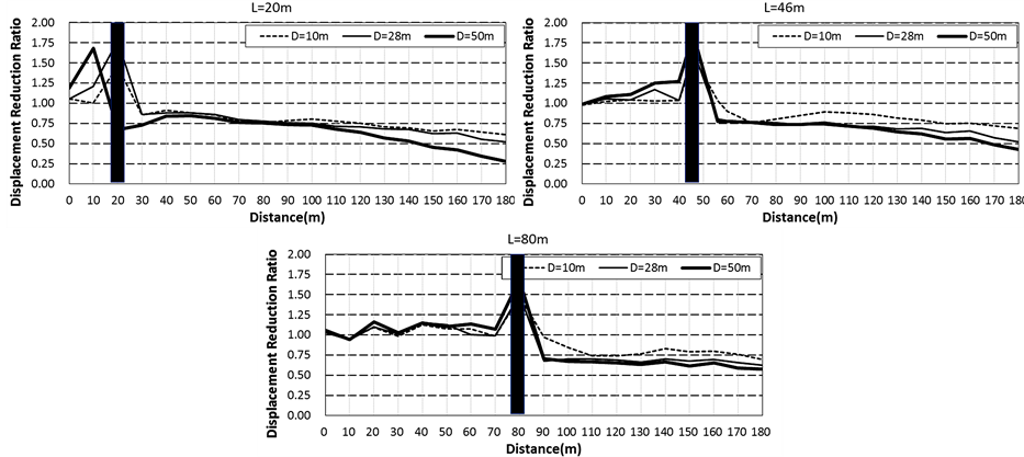
Figure 6. Displacement reduction ratioby trench.
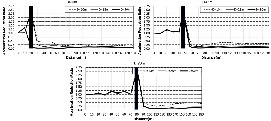
Figure 7. Acceleration reduction ratio by trench.
quency content of Figure 5 during the travelling of the tilting train in the curved section (R = 1200 m), which explains the relatively lower blocking performance of the surface wave by the trench with depth of 10 m.
3.2. Vibration-Blocking by Wave Barrier
The vibration-blocking effect of the trench is known to be generally superior to that provided by the wave barrier. However, the use of the wave barrier is proposed due to the structural instability of the trench. Accordingly, numerical analysis is performed to examine the vibration-blocking effect by the wave barrier. Bentonite slurry, a ductile material, and concrete, a hard material, are used as infill of the wave barrier. For comparison with the trench, analysis is performed by fixing the distance from the vibration source (L = 46 m) and the depth of the trench (D = 28 m). Table 1 arranges the properties of the infill materials used for the wave barrier, and Figures 8 and 9 plot the analysis results.
Figures 8 and 9 present the amplitude reduction ratios provided by the trench and, the wave barriers filled with concrete and bentonite slurry. Here, the wave barrier with concrete infill appears to provide smaller reduction ratio than the wave barrier with bentonite slurry infill and the trench. Accordingly, in view of the analysis results, the use of ductile infill appears to be more efficient in terms of ground vibration-blocking effect for the travelling tilting train.

Table 1. Properties of infills of wave barrier.
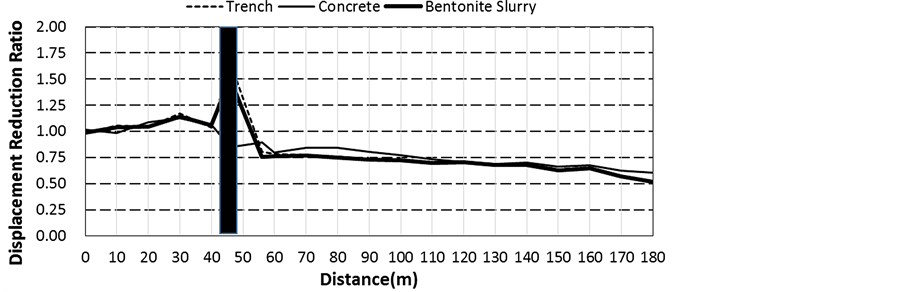
Figure 8. Displacement reduction ratioby wave barrier.
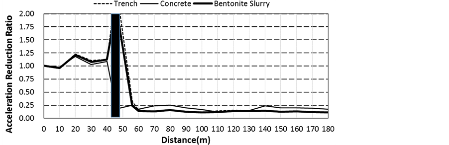
Figure 9. Acceleration reduction ratioby wave barrier.
4. Conclusions
This study clarified the vibration-generation mechanism of the tilting train in the existing conventional track using a dynamic model of the track and train. The characteristics of the propagation of the vibration generated by the travelling train were investigated to identify the vibration-blocking effect provided by anti-vibration structures installed on the vibration propagation path. The following conclusions can be drawn.
1) Propagation characteristics of ground vibration generated by the travelling tilting train: Higher displacement and acceleration vibration levels were measured during the travelling of the tilting train than the travelling of any previous trains in both straight and curved sections. Especially, higher vibration level was measured in the centrifugal direction due to the adjusting cant and centrifugal force during the crossing of the curved section. The frequency contents of all the responses (displacement and acceleration) appeared to shift toward the high frequency domain according to the increase of the train speed. Moreover, different frequencies were observed for the maximum amplitudes of the displacement and acceleration for the same train speed.
2) Vibration-reduction measures of ground vibration: The ground vibration energy generated near surface far by a definite distance from the vibration source which is caused by the surface wave. Therefore, the reduction of ground vibration shall be achieved by reducing the transfer of the surface wave energy. Following, this study clarified the vibration-blocking effect of anti-vibration structures as the vibration-blocking method of the vibration path. The wave barrier with concrete infill provided smaller reduction ratio than the wave barrier with bentonite slurry infill and the trench. Accordingly, the use of ductile infill appeared to be more efficient in terms of ground vibration-blocking effect.
Since 2D numerical analysis was conducted in this study, attention should be paid on the fact that the angle of incidence is always perpendicular to the wave barrier. In other words, since the incident vibration during the train travelling is always inclined to the wave barrier installed near the track, it cannot be affirmed that the ductile wave barrier is more effective in such case. This is due to the mode conversion of the stress wave preponderating the vibration propagation, which can improve the vibration-blocking effect of the ductile wave barrier according to the angle of incidence [5] . This feature has been reported in other research results. Consequently, need is for further research dedicated to the problem of the wave barrier with an angle of incidence.
References
- Kim, H.S. (2013) A Study on the Characteristics for the Ground Vibration Due to the Travelling Tilting Train. Engineering, 5, 729-734. http://dx.doi.org/10.4236/eng.2013.59087
- Yang, S.C., Kim, T.O. and Kang, Y.S. (2004) Reduction Methods of Noise and Vibration for Railway Line Structure of High-Speed Train. Korean Society for Noise and Vibration Engineering, 14, 26-34.
- Yoo, Y.H., Um, J.H. and Eum, K.Y. (2003) Allowable Speed of Tilting Car in the Conventional Line. Journal of the Korean Society for Railway, 6, 246-251.
- Woods, R.D. (1968) Screening of Surface Waves in Soils. Journal of the Soil Mechanics and Foundations Division, American Society of Civil Engineers, 94, 951-979.
- Lee, J. and Its, E. (1995) Surface Waves of Oblique Incidence across Deep Infilled Trenches. Journal of Engineering Mechanics, 121, 482-486. http://dx.doi.org/10.1061/(ASCE)0733-9399(1995)121:3(482)