Engineering
Vol.5 No.1A(2013), Article ID:27325,8 pages DOI:10.4236/eng.2013.51A021
The Experiment and Simulation of Solid Desiccant Dehumidification for Air-Conditioning System in a Tropical Humid Climate
Department of Mechanical Engineering, Faculty of Engineering, Prince of Songkla University, Hat Yai, Songkhla, Thailand
Email: *juntakan@me.psu.ac.th, v_akvanich@hotmail.com
Received November 15, 2012; revised December 16, 2012; accepted December 25, 2012
Keywords: Solid Desiccant; Dehumidification; Air-Conditioning System; Tropical Humid Climate
ABSTRACT
The aim of this research was to study and design a solid desiccant dehumidification system suitable for tropical climate to reduce the latent load of air-conditioning system and improve the thermal comfort. Different dehumidifiers such as desiccant column and desiccant wheel were investigated. The ANSYS and TRASYS software were used to predict the results of dehumidifiers and the desiccant cooling systems, respectively. The desiccant bed contained approximately 15 kg of silica-gel, with 3 mm average diameter. Results indicated that the pressure drop and the adsorption rate of desiccant column are usually higher than those of the desiccant wheel. The feasible and practical adsorption rate of desiccant wheel was 0.102 kgw/h at air flow rate 1.0 kg/min, regenerated air temperature of 55˚C and at a wheel speed of 2.5 rpm. The humidity ratio of conditioning space and cooling load of split-type air conditioner was decreased to 0.002 kgw/kgda (14%) and 0.71 kWth (19.26%), respectively. Consequently, the thermal comfort was improved from 0.5 PMV (10.12% PPD) to 0.3 PMV (7.04% PPD).
1. Introduction
A principal purpose of Heating Ventilation and Air Conditioning (HVAC) is to provide thermal comfort conditions for humans. In general, comfort occurs when body temperatures are held within a narrow range, skin moisture is low, and the physiological effort of regulation is minimized. As reference by ANSI/ASHRAE Standard 55 (1992) [1], the acceptable ranges of operative temperature and relative humidity are 20˚C - 26˚C and 30% - 60%, respectively. In the tropical region, such as Thailand climatic zones, the conditions at 26˚C and 50% - 60% relative humidity are considered as a comfortable environment condition [2]. Air-conditioning loads can be divided into two components, namely the sensible and the latent loads. Latent load involves removal of moisture in the air. In areas of high humidity, moisture presents a major problem for the human comfort and the air-conditioning systems, and therefore, unitary dehumidifiers should be used. Both mechanical refrigeration systems and desiccant material can remove the moisture from the supply air, whereas desiccant dehumidification is advantageous in dealing with latent load and improving indoor air quality because of adsorbing moisture directly. The desiccants are natural or synthetic substances capable of absorbing or adsorbing water vapour due to the difference of water vapour pressure between the surrounding air and the desiccant surface. Many desiccant materials are available, such as silica-gel, activated alumina, molecular sieve, alumina gel, etc. In other words, silica-gel has a high capacity for water, a low temperature for regeneration, and no sulfur conversion reactions [3]. The dehumidification processes of air are important operation in various applications. In common practice, dehumidification usually refers to equipment operating at essentially atmospheric pressures and built to standards similar to other types of air-handling equipment. The solid desiccant dehumidifiers usually employ stationary beds or rotary wheel beds for packing the desiccant media, namely desiccant column and desiccant wheel, respectively. In the former case, two or more desiccant columns are constructed with a set of valves to make these stationary beds work alternatively in adsorption and regeneration phase. Secondly, dehumidifier, the air to be dried flows through one side of the wheel, while at the same time, the heated air stream dries the desiccant on the other side of wheel. The desiccant column is also widely used in the process of air dehumidification or drying. There are several desiccant column configurations including solid packed bed, multiple vertical beds, radial bed, and inclined bed which have been used for dehumidification. Adsorption-desorption operations of a hollow cylindrical packed bed were investigated by Awad et al. [4]. The pressure drop in radial bed is too small comparing with that for the vertical bed. The effect of flowbed geometries on desiccant column were investigated by Visit and Juntakan [5]. The hollow cylindrical bed was the feasible and practical dehumidifier for dehumidification process. With respect to desiccant wheels, a study on solid desiccant based hybrid air-conditioning systems was reported by Dhar and Singh [6]. The evaluation and optimization of solar desiccant wheel (rotating honeycomb) performance was reported by Ahmed et al. [7]. Nia et al. [8] presented the modeling of a desiccant wheel used for dehumidifying the ventilation air of an air-conditioning system.
In this study, the dehumidifiers were used in dehumidifying the incoming air stream by forcing it through a structured packing impregnated with silica-gels for the latent load reduction of air-conditioning system and the thermal comfort improvement. In this paper, simulations were used to predict the performance of dehumidifiers and the desiccant cooling systems. The commercial software programs, namely ANSYS and TRASYS were used for simulations. Moreover, experimental tests were also conducted under tropical humid climate incorporating the applicable criteria that follow.
2. Dehumidifier and Desiccant Cooling
The desiccant dehumidifiers under investigation are shown in Figure 1. The spherical particles of silica-gel were used as the working desiccant in the dehumidifiers. Amount of desiccant in the bed is close to 15 kg of silicagel. The physical properties of silica-gel are: average diameter: 3 mm, porosity: 0.4 (the open volume fraction of the medium) and bulk density: 670 kg/m3. The bed geometry of the stationary dehumidifier on desiccant column is radial, i.e. a hollow cylindrical bed. For rotary beds, the desiccant wheel is divided into two equal parts
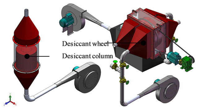
Figure 1. The types of solid desiccant dehumidifiers.
for dehumidification and regeneration process. The air to be dried flows through one side of the wheel, while at the same time, the heated air stream dries the desiccant on the other side of wheel. The desiccant cooling system under investigation consisted of dehumidification and air-conditioning systems. The first system was used to remove water vapor from the ventilation air before passing into the air-conditioning system. The second system consists of split type air conditioner to maintain the desired indoor conditions, the thermal comfort conditions for human.
3. Simulation
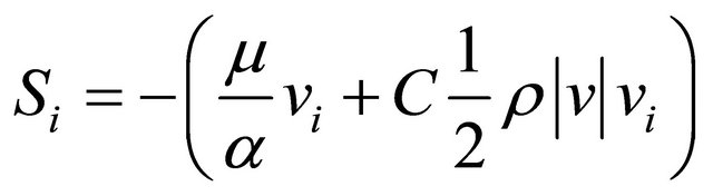
The simulations were used to predict the results of the dehumidifiers and the desiccant cooling system. ANSYS software, a computational fluid dynamics (CFD) program which is often used to solve the governing equation such as the Navier-Stokes or energy equations by numerical method, was used to study and design the solid desiccant dehumidifiers. In this study, the desiccant column and desiccant wheel involves modeling the multiphase flow through porous media. Mixture model in the Euler-Euler approach is a simplified multiphase model. It can be used to model multiphase flows where the phases move at different velocities. The porous media model, which is used for a wide variety of single phase and multiphase problems, including flow through packed beds, filter papers, perforated plates, flow distributors, and tube banks, adds a momentum source term to the standard fluid flow equations. The source term composed of two parts: a viscous loss term, and an inertial loss term. In a simple homogeneous porous media case, it can be represented as Equation (1) [9].
 (1)
(1)
where Si is the source term for the momentum equation (kg/m2∙s2),  is the magnitude of the velocity (m/s), µ and ρ being dynamic viscosity (N∙s/m2) and density of fluid properties (kg/m3) respectively, α is the permeability and C is the inertial resistance factor. Under the finite volume method [10], although the first-order upwind scheme discretization can yield better convergence, it generally will lead to less accurate results with only firstorder accuracy. Therefore, the quadratic upwind differencing scheme (QUICK scheme) discretization with third-order accuracy is used in calculating momentum, volume fraction, turbulence kinetic energy and its dissipation rate, and Reynolds stress equations. SIMPLEC arithmetic is used in pressure-velocity coupling in order to accelerate the convergence of the continuity equation. PRESTO! Scheme is applied in discretizing pressure gradient taking into account non-staggered grid. TRNSYS software, a transient simulation program which consists of many sub-routines that mathematical models for the subsystem components are given in terms of their ordinary differential or algebraic equations, was used to investigate and predict the air-conditioning system. The details of the experiment room in the low energy house located at Prince of Songkla University were used to construct the model for simulation. Two system configurations were used for experiment. The first system couples the air-conditioning installation to the building. The second system couples the desiccant dehumidification to the previous one. The considered parameters were the using of energy consumption and assessing thermal comfort.
4. Experimental Setup and Method
In this study, the experimental setup consisted of dehumidification and air-conditioning systems set up at the 2nd floor of the low energy house in Prince of Songkla University located in the Southern part of Thailand, as shown in Figure 2. The experimental dehumidification system used the desiccant dehumidifiers to remove water vapor from the ventilation air before passing into the air-conditioning system. The desiccant wheel testing is illustrated in Figure 3.
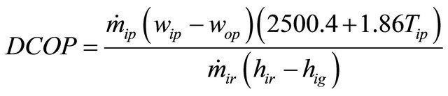
The experimental dehumidification system consisted of a rotary desiccant wheel with a diameter of 0.5 m and a length of 0.2 m containing 15 kg of silica gel. The factors changed in the parametric studies included the air flow rate (ṁi), wheel speed (Rev), inlet temperature (Ti) and inlet humidity ratio (wi) of the dehumidification and regeneration process. The air flow rate was kept around 18, 60 and 102 kg/h by a ventilation fan driven by an inverter. The wheel speed varied at 1.0, 2.5 and 4.0 rpm by a motor driven by an inverter. The inlet temperature of the dehumidification process (Tip) and the regeneration process (Tir) were kept around 24.5˚C, 27.5˚C, 32.5˚C and 45˚C, 55˚C, 65˚C, respectively by a heater with temperature control. Moreover, the inlet humidity ratio of the dehumidification process (wip) and the regeneration process (wir) were kept around 0.010, 0.015 and 0.019 kgw/ kgda by using a separate dehumidifier. The performance of dehumidifiers was evaluated based on two different criteria. The first parameter was the moisture removal capacity. The second parameter was the dehumidification coefficient of performance (DCOP), which reflects the reduction of latent heat in dehumidification process and the energy consumption during regeneration process; it can be mathematically expressed using Equation (2) [11].
 (2)
(2)
where DCOP is the coefficient of performance; ṁip and ṁir are flow rate of process air and regeneration air, re-
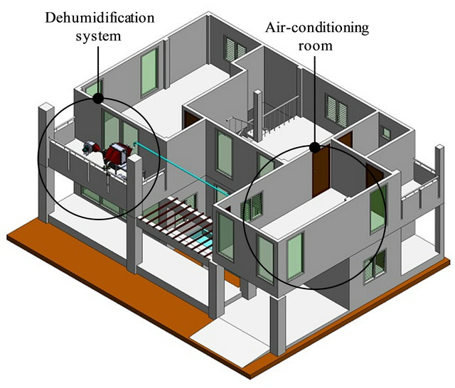
Figure 2. The experiment setup (PSU low energy house).
spectively (kg/s); wip and wop are humidity ratio of inlet and outlet process air, respectively (kgw/kgda); hir and hig are enthalpy (kJ/kg) of inlet and outlet regenerate air, respectively, and Tip is temperature (˚C) of inlet process air. In the desiccant cooling system, the dry air which passed through the dehumidifier was passed into the air-conditioning system by forced ventilation. The desiccant cooling system is depecited in Figure 4.
The important data, such as the temperature (Tia) and humidity ratio (wia) of indoor air, the temperature (Toa) and humidity ratio (woa) of outdoor air, the temperature of supply air (Tsa) and return air (Tra), the air temperature of the dehumidification process (Tip) and the regeneration process (Tir), or the air flow rate of the dehumidification process (ṁip) and the regeneration process (ṁir) were collected. In addition, the thermal comfort (predict mean vote, PMV, and predicted percentage dissatisfied, PPD) were calculated using the equations proposed by Fanger [12]. The PMV values ranges from –1 to +1, with the ranges –0.5 to 0.5 indicating comfortable, 0.5 to 1.0 indicating warm, and –1.0 to –0.5 indicating cool. PMV values over 1.0 means unacceptably warm, and those under –1.0 means unacceptably cool.
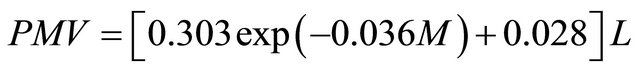 (3)
(3)
where PMV is predict mean vote. M is rate of metabolic heat production (W/m2) and L is the thermal load on the body (W/m2). Furthermore, the equation for PPD is given by Equation (4). PPD is used to estimate the thermal comfort satisfaction of the occupant.
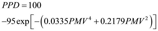 (4)
(4)
Dissatisfied is defined as anybody not voting –1, +1, or 0. For example, the PPD of 10% corresponds to the
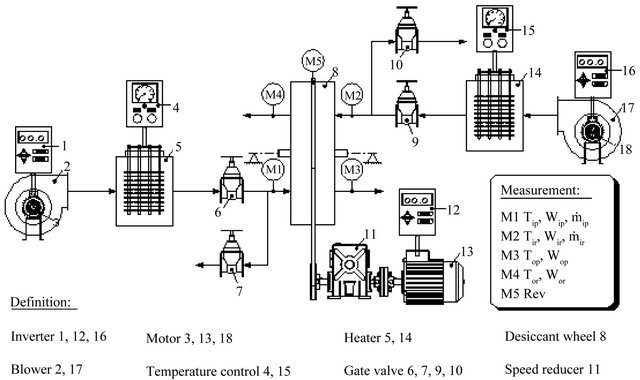
Figure 3. Schematic diagram of desiccant wheel testing.
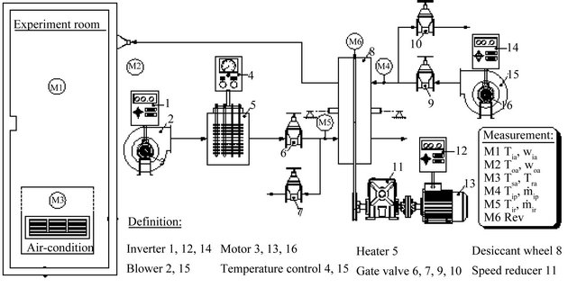
Figure 4. Schematic diagram of desiccant cooling system.
PMV range of ±0.5, and even with PMV = 0, about 5% of the people are dissatisfied.
5. Results and Discussion
Two dehumidification systems were simulated using the computational fluid dynamics. The first dehumidifier has a column type desiccant media installation. The second dehumidifier has a wheel type desiccant media installation. Simulation results revealed that the pressure drop of desiccant column is higher compared to the desiccant wheel under the same conditions, but the adsorption rate of the desiccant column is also higher than the desiccant wheel. With amount of desiccant in the bed being close to 15 kg of silica-gel, at an air flow rate of 60 kg/h, the predicted static pressure and humidity ratio distributions through simulation for the desiccant wheel and desiccant column are given in Figure 5 and Figure 6 respectively. The desiccant column had high static pressure (34.49 Pa) in bottom column or inlet zone (red zone) and zero Pa (gage) in outlet zone to ambient (blue zone). The desiccant wheel had a pressure drop less than 25.77 Pa. For inlet moist air with humidity ratio of 0.0180 kgw/kg (red zone) passed through desiccant media, the humidity ratio at the outlet of the desiccant column decreased to 0.0154 kgw/kg (orange zone). In the case of the desiccant wheel, humidity ratio at the outlet dropped to 0.0168 kgw/kg (yellow zone). The velocity fields inside central plane of the desiccant column and the desiccant wheel predicted through simulation are also shown. These predictions were with a mass flow rate of 60 kg/h. The results dis-
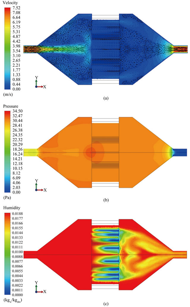
Figure 5. The contour plots inside central plane (z = 0) of the desiccant wheel (adsorption part). (a) Contour plots of velocity; (b) Contour plots of static pressure; (c) Contour plots of humidity ratio.
play the air-stream patterns with a collection of vector arrows. The magnitude of velocity is represented by the colours. The maximum magnitude of velocity occurred in the centre and middle layer of the dehumidifiers. A reverse swirl was found near the inlet and outlet regions of the desiccant column. A swirl appeared only near the inlet region of desiccant wheel.
In the physical experiment with desiccant wheel dehumidifier, the effect of the parametric studies such as air flow rate, wheel speed or inlet temperature and inlet hu-
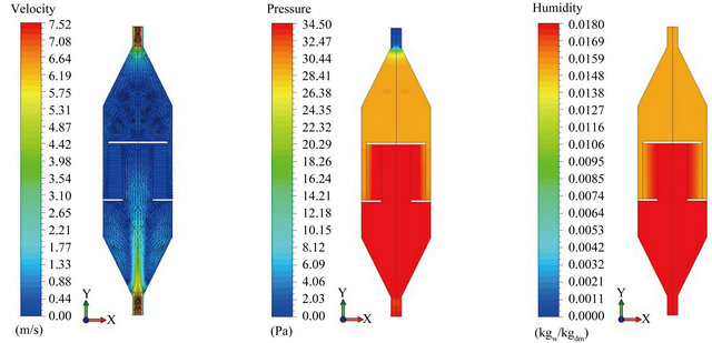
Figure 6. The contour plots inside central plane (z = 0) of the desiccant column.
midity ratio of dehumidification and regeneration process were considered. The dehumidification coefficient of performance was particularly defined for to find the feasible and practical condition for dehumidifier. The experiment results revealed that the effects of air flow rate and air temperature on DCOP are more than those of the humidity ratio and wheel speed. The highest DCOP and the adsorption rate achieved with the desiccant wheel were 0.25 and 0.102 kgw/h, respectively, at an air flow rate of 1.0 kg/min, regenerated air temperature of 55˚C and 2.5 rpm wheel speed. The relationship between the DCOP of the desiccant wheel with different variables are shown in Figure 7. In Figure 7, different variables are normalized by dividing a given variable value by the mean value of that variable.
The results of the desiccant cooling system are compared with the standard air-conditioning system in Figure 8. The variations of the different quantities within the experimental room with the standard air-conditioning system, are shown in Figure 8(a). The measured temperature (Toa-Exp) and relative humidity (Rhoa-Exp) of the outdoor air were in the ranges of 26.7˚C - 31.6˚C and 62.8% - 95.0%, respectively, whereas, the measured average temperature (Toa-Exp) and relative humidity (Rhoa- Exp) of the indoor air were around 25.3˚C and 60.4%. The variations of the same quantities within the experimental room with the desiccant cooling system are shown in Figure 8(b). The desiccant wheel operated at an air flow rate of 1.0 kg/min, regenerated air temperature of 55˚C and 2.5 rpm wheel speed. When the temperature and the relative humidity of the outdoor air were in the ranges of 25.5˚C - 32.7˚C and 55.5% - 95.6%, respectively, the average temperature and relative humidity of the indoor air were found to be around 25.3˚C and
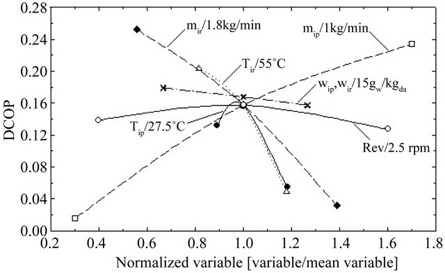
Figure 7. The variation of dehumidification coefficient of performance of desiccant wheel with different parameters.
52.3%. Results indicate that the humidity ratio of conditioning space and cooling load of split type air conditioner were decreased by 0.002 kgw/kgda (14%) and 0.71 kWth (19.26%) respectively. Consequently, the predicted mean vote was improved from 0.3 - 0.6 (0.5 averages value) to 0.1 - 0.4 (0.3 averages value) or the predicted percentage dissatisfied was reduced from 6.77% - 12.85% (10.12% averages value) to 5.17% - 8.81% (7.04% averages value). Furthermore, the predicted value such as the temperature (Toa-Sim) and relative humidity (Rhoa-Sim) within the experimental room were in good agreement with the experiment measurements. The average errors of prediction were less than 2.1% and 5.4% for the temperature and the relative humidity of the interior air, respectively. In short, from this research work under the tropical humid region condition which being hot and high humidity, the desiccant dehumidification has an extreme effect. However, in dry region condition, the adsorption rate maybe decreases since the different of
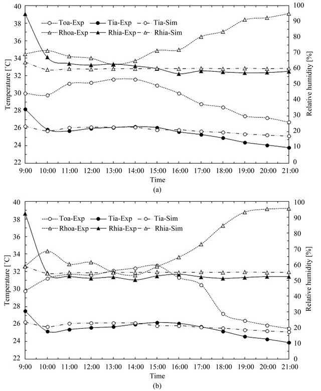
Figure 8. The experiment and prediction of interior air conditions. (a) The air-conditioning systems; (b) The desiccant cooling systems.
water vapor is lower. Furthermore, in the air-conditioning system with the solid desiccant dehumidification, it cannot only decrease the energy consumption but also develop occupant’s thermal comfort.
6. Conclusion
Two solid desiccant dehumidification system designs suitable for tropical humid climate meant for the reduction of latent load of air-conditioning systems and improvement of the thermal comfort were proposed and the performance was analyzed through simulations and experimental studies. The simulations were performed using the commercial software packages ANSYS and TRASYS. The desiccant dehumidifier designs under investigation were the stationary desiccant column and the rotary desiccant wheel. Amount of desiccant in the bed was 15 kg, and the desiccant considered was silica-gel, with average diameter of 3 mm. The main findings of the simulation study are: the pressure drop and the adsorption rate of desiccant column are higher than those of the desiccant wheel; the most feasible and practical adsorption rate of the desiccant wheel used in this experiment was 0.102 kgw/h at air flow rate 1.0 kg/min, regenerated air temperature 55˚C and at 2.5 rpm wheel speed; the effect of air flow rate and air temperature on DCOP were more than that of the humidity ratio and wheel speed. The experimental studies with a desiccant wheel humidifier coupled to a split type air conditioner confirmed the accuracy of simulations. Use of desiccant cooling system reduced the humidity ratio of conditioned space and the cooling load of the air conditioner by 14% and 19.26% respectively. Consequently, the thermal comfort was improved from 0.5 PMV (10.12% PPD) to 0.3 PMV (7.04% PPD).
7. Acknowledgements
This research was financially supported by the Energy Policy and Planning Office (EPPO), Ministry of Energy, Thailand and Prince of Songkla University for providing the research scholarship.
REFERENCES
- ANSI/ASHRAE Standard 55-1992, “Thermal Environmental Conditions for Human Occupancy,” ASHRAE, Inc., Atlanta, 1992.
- N. Yamtraipat, J. Khedari and J. Hirunlabh, “Thermal Comfort Standards for Air Conditioned Buildings in Hot and Humid Thailand Considering Additional Factors of Acclimatization and Education Level,” Solar Energy, Vol. 78, No. 4, 2005, pp. 504-517. doi:10.1016/j.solener.2004.07.006
- P. Gandhidasan, A. A. Al-Farayedhi and A. A. Al-Mubarak, “Dehydration of Natural Gas Using Solid Desiccants,” Energy, Vol. 26, No. 9, 2001, pp. 855-868. doi:10.1016/S0360-5442(01)00034-2
- M. M. Awad, A. K. Ramzy, A. M. Hamed and M. M. Bekheit, “Theoretical and Experimental Investigation on the Radial Flow Desiccant Dehumidification Bed,” Applied Thermal Engineering, Vol. 28, No. 1, 2008, pp. 75- 85. doi:10.1016/j.applthermaleng.2006.12.018
- V. Akvanich and J. Taweekun, “Computational Fluid Dynamics (CFD) Simulations for the Effect of Flow-Bed Geometries on Desiccant Column,” Proceedings of the Annual International Conference of the FDTT, Singapore, 17-18 March 2012, pp. 19-24.
- P. L. Dhar and S. K. Singh, “Studies on Solid Desiccant Based Hybrid Air-Conditioning Systems,” Applied Thermal Engineering, Vol. 21, No. 2, 2001, pp. 119-134. doi:10.1016/S1359-4311(00)00035-1
- M. H. Ahmed, N. M. Kattab and M. Fouad, “Evaluation and Optimization of Solar Desiccant Wheel Performance,” Renewable Energy, Vol. 30, No. 3, 2005, pp. 305- 325. doi:10.1016/j.renene.2004.04.010
- F. E. Nia, D. V. Paassen and M. H. Saidi, “Modeling and Simulation of Desiccant Wheel for Air Conditioning,” Energy and Building, Vol. 38, 2006, pp. 1230-1239. doi:10.1016/j.enbuild.2006.03.020
- ANSYS FLUENT, “Technical Specifications Public Notice,” ANSYS, Inc., Canonsburg, 2009.
- H. K. Versteeg and W. Malalasekera, “An Introduction to Computational Fluid Dynamics, the Finite Volume Method,” Longman Limited, London, 1995.
- M. Kanoglu, M. O. Carpinlioglu and M. Yildirim, “Energy and Exergy Analyses of an Experimental Open-Cycle Desiccant Cooling System,” Applied Thermal Engineering, Vol. 24, No. 5-6, 2004, pp. 919-932. doi:10.1016/j.applthermaleng.2003.10.003
- P. O. Fanger, “Thermal Comfort,” Danish Technical Press, Copenhagen, 1970.
NOTES
*Corresponding author.