Engineering
Vol. 4 No. 6 (2012) , Article ID: 19857 , 5 pages DOI:10.4236/eng.2012.46042
Finite Element Modelling of Insulation Thicknesses for Cryogenic Products in Spherical Storage Pressure Vessels
Department of Mechanical Engineering, University of Ibadan, Ibadan, Nigeria
Email: deleadeyefa@yahoo.com
Received November 20, 2011; revised February 10, 2012; accepted February 16, 2012
Keywords: NASA; LPG; LNG; FEM; EIA; FORTRAN 90; ANOVA; Cryogenic; ASME; BS
ABSTRACT
This study investigates various insulation thicknesses requirements for double-walled spherical pressure vessels for the storage of cryogenic liquids. The inner tank is suspended from the outer tank by straps or cables and the annular space between the tanks is filled with insulation. The outer tank is not subjected to the freezing temperatures and is thus assumed to be a standard carbon steel sphere. In the Finite Element Analysis model of the system, one dimensional analysis was employed. This is due to the assumption that temperature gradient does only exist along the spherical radial direction. In the developed model, once the thickness of the inner shell has been determined based on relevant standards and codes—ASME Sec VIII Div 1 or 2, BS 5500 etc and the thickness of the outer shell is known; the required insulation material thicknesses were calculated for different insulating materials. Set of equations resulting from Finite Element Analysis were solved with computer programme code which was written in FORTRAN 90 programming language. The results obtained are validated by analytical method. The results showed no significant difference (P > 0.05) with values obtained through analytical method. The thicknesses for different insulating materials in-between inner and outer tank shells were compared. The results showed that as the insulating material thickness was increased, the heat flux into the stored product was decreasing and at a certain thickness; it started increasing. The insulating thickness at which this happens is termed as critical thickness of insulating material—the thickness of insulation at which the heat influx to the stored products is minimal; this would therefore reduce boil-off of the stored cryogenic product. High thermal conductivity insulating materials need to be thicker than lower thermal conductivity insulating materials if the system is conditioned to have the same heat flux into the stored product for all insulating materials. In the simulation, different insulating material gives different minimal heat influx into the stored products.
1. Introduction
The combination of higher natural gas prices, rising natural gas demand, and lower liquefied natural gas (LNG) production costs, is setting the stage for increased LNG trade in the years ahead. Estimates are that worldwide LNG trade will increase 35 percent by 2020. In the United States, Energy Information Administration (EIA) projects that natural gas imports will more than double over the next 20 years. Nearly all the projected increase is expected to come from LNG, requiring an almost 28-fold increase in LNG imports over 2002 levels, [1]. The need for reduced weight, in combination with good insulating properties for long term storage provides a new challenge for cryogenic tank design. These new designs provide an opportunity to apply advanced materials, structural concepts and finite element method in an effort to reduce the overall weight of the tank, reduce the boil off, and keep the volume at an acceptable and practical level. Although, the design of a cryogenic storage tank, involves many challenges, the most dominant ones include geometry and temperature.
In the present study we performed temperature gradient study on a double-walled, insulated jacketed, field fabriccated spherical cryogenic tank wherein determine insulation thickness.
2. Literatures Review
[2], in their paper verified that commercially available pressure vessels could be safely used to store liquid hydrogen. The use of commercially available pressure vessels significantly reduces the cost and complexity of the insulated pressure vessel development effort. This paper describes a series of tests that have been done with aluminum-lined, fiber-wrapped vessels to evaluate the damage caused by low temperature operation.
A Seismic post elastic behavior of LPG spherical storage tanks study was performed by [3] for an existing equipment with a volume of 1000 m3 containing 85% of LPG. The middle diameter of the sphere is 12.50 m; its thickness varies from 36.2 mm to 36.8 mm taking into account the corroded thickness. [4], gave a description of a fatigue analysis method based on the S-N curve and crack propagation method. The presentation of the method is based on an application to a practical example taken from Ship building, i.e., the analysis of details of membrane LNG carriers of the Gas Transport system type. [5] carried out research on the technology development and alternate fuel foundation technologies that will greatly reduce or even eliminate environmentally harmful emissions. Because of this, liquid hydrogen has emerged as a propellant to supply the fuel needs for future aircraft due to its high energy per unit mass. Durable, lightweight cryogenic propellant storage and feed systems are required to enable the development of hydrogen-fueled aircraft. As a result, there is a need for hydrogen tank storage systems for these aircraft applications, which are expected to provide sufficient capacity for flight durations ranging from a few minutes to several days [6].
3. Finite Element Methodology
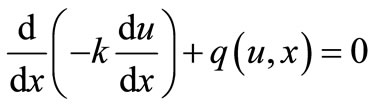
In this analysis, finite element is adopted in solving a partial differential equation in one-dimensional steadystate heat equation.
Rate of change of heat flux = heat source per unit volume
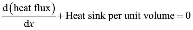
 (1.0)
(1.0)
where u = The nodal temperature in ˚C;
k = Thermal conductivities in Watts/m/˚C;
q = Heat sink per unit volume in Joules/m3;
x = Distance from the inner wall of inner spherical shell to the outer wall of outer spherical shell in metres.
3.1. Model Assumptions
1) The heat gradient to be in radial direction only;
2) The stored cryogenics product are assumed as sink;
3) The atmospheric surrounding as the heat source;
4) Thermal conductivity, k (Watts/m/˚C) is not temperature or position dependent.
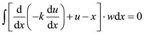
To solve Equation (1.0), weighted residual analysis is applied to give for of Equation (2.0)
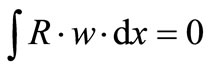 (2.0)
(2.0)
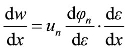
where R is the residual taking from Equation (1.0) and w is the weighting function.
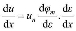
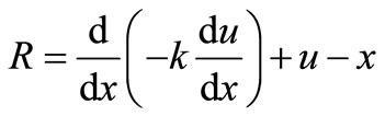 (3.0)
(3.0)
If u and x are exact solutions over the whole domain, the residual R would be zero everywhere. Substituting Equation (3.0) into Equation (2.0) gives
 (4.0)
(4.0)
This formulation of the governing equation can be thought of as forcing the residual to be zero in a spatially averaged sense.
Solving Equation (4.0) above, thus gives
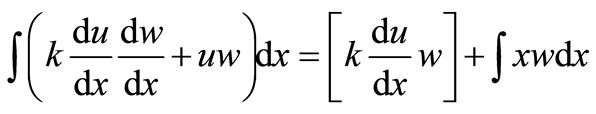 (5.0)
(5.0)
3.2. Finite Element Approximation
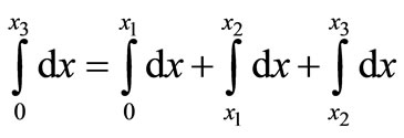
The domain is divided into three different length elements and replaces the continuous field variable within each element by the parametric finite element approximation.
The domain integral in Equation (5.0) can now be replaced by the sum of integrals taken separately over the three elements—inner spherical shell, insulating material and outer spherical steel shell as showing in Figure 1.
 (7.0)
(7.0)
and each element integral is normalizing to  -space
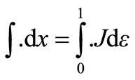 (8.0)
(8.0)
where  the Jacobian of the transformation from x coordinates to
  coordinates.
The element integrals arising from the LHS of Equation (5.0) then have the form
 (9.0)
(9.0)
where  and
and  since
since  and
and  are both functions of
 .
.
But
 (10.0)
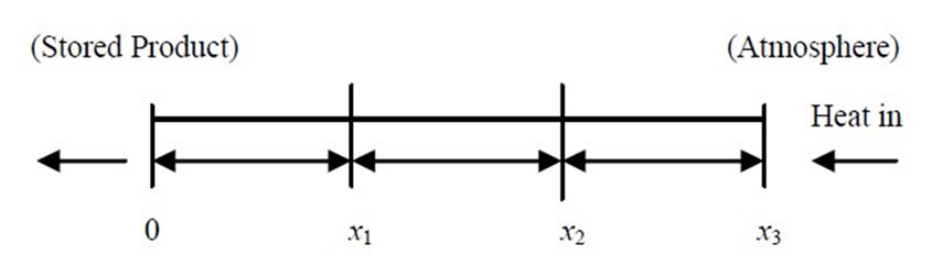
Figure 1. Showing element divisions of spherical storage pressure vessel.
 (11.0)
Substituting Equations (10.0) and (11.0) into Equation (9.0) then
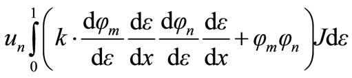 (12.0)
un is taken outside the integral in the equation above because it is not a function of ε.
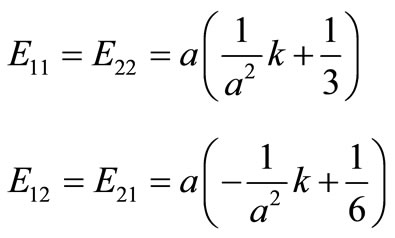
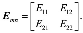
The term multiply un in Equation (12.0) above is term as stiffness matrix. Therefore, stiffness matrix Emn is
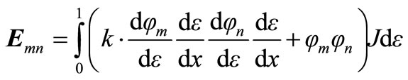 (13.0)
3.3. Element Stiffness Matrix
Equation (13.0) gives the element stiffness matrix. The indices m and n in the equation can only take values of 1 or 2. To solve stiffness matrix for element 1, finite element relation between x and ε coordinates is taken as .
.
a = thickness of element measured in metre.
Therefore, .
.
Jacobian, .
.
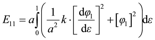
Substituting for Jacobian, J in Equation (13.0) leads to
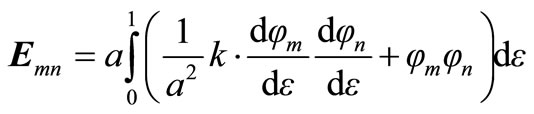 (14.0)
where the indices m and n are 1 or 2. To evaluate Emn, we substitute the basic functions 1, 2
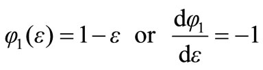 (15.0a)
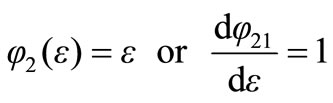 (15.0b)
 (16.0)
Substitute Equation (15.0) into the Equation (16.0) and integrate.
 (17.0)
The above equations give the stiffness matrix for element 1; this can be written in a matrix form
3.4. System Stiffness Matrix
The three element stiffness matrices calculated elements 1, 2 and 3 are assembled into system global matrix.
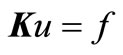 (18.0)
f = is the heat flux (joules/m2).
K = System stiffness matrix.
f is the heat flux corresponding to the first term of the RHS of Equation (5.0). To solve the integral part of the second terms of Equation (5.0) which is the source term, replacing the domain integral for the x-source term by the sum of three element integrals
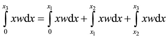 (19.0)
Normalizing Equation (19.0) to ε coordinates as it was done in Section 3.2, and then solving the element integral as it is done in Section 3.3. The solved x-source terms are assembled and added to the right hand term of the system matrix Equation (18.0). Therefore, the system matrix equation becomes
 (20.0)
s = assembled matrix representing source term.
3.5. Boundary Conditions
Essential Boundary Conditions
The boundary conditions u(0) = T1 and u(1) = T4 are applied directly to the first and last nodal values where
T1 is the temperature of the cryogenic product stored inside the spherical storage tank (˚C);
T4 is the maximum ambient temperature (˚C).
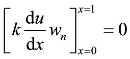
Flux Boundary Conditions
The flux terms in the right hand side of Equation (5.0)
 (21)
(21)
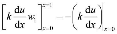
For node 1 w1 is obtained from the basis function  associated with the first node of element 1 and therefore,
 .
.
Also, since w1 is identically zero outside element 1, .
.
Thus Equation (20) for node 1 reduces to
 (22)
(22)
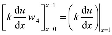
Similarly, for nodes 2 and 3
and for node 4
4. Results and Discussions
Case 1
In order to validate the finite element procedure used, below are the conditions under which the simulation was carried out to determine the temperature profile across the thickness of spherical shell divides into 3 equal elements.
Thickness of each element of Carbon Steel spherical shell = 0.3333 m;
Carbon steel thermal conductivity = 1.0 W/m ˚C;
Stored product (LNG) temperature = 0.0˚C;
Ambient temperature = 1.0˚C.
It can be seen from the Table 1 above that FEA exact values are in good agreement.
Case 2
Optimum insulation thicknesses are determined for different insulating materials for a spherical storage pressure vessel containing liquefied natural gas (LNG). Below are the conditions under which the simulation to determine different insulation thicknesses were carried out:
Thickness of carbon steel inner shell = 0.024 m;
Thickness of carbon steel outer shell = 0.006 m;
Carbon steel thermal conductivity = 43.0 W/m ˚C;
Stored product (LNG) temperature = –162˚C;
Ambient temperature = 45.0˚C.
Table 2 shows the required insulating material thickness for spherical storage vessel stores Liquefied Natural Gas (LNG).
Case 3
Optimum insulation thicknesses are determined for different insulating materials for a spherical storage pressure vessel containing liquefied hydrogen (H2(l)). Below are the conditions under which the simulation to determine different insulation thicknesses were carried out:
Thickness of carbon steel inner shell =0.024 m;
Thickness of carbon steel outer shell = 0.006 m;
Carbon steel thermal conductivity = 43.0 W/m ˚C;
Stored product (liquefied hydrogen, H2(l));
Temperature = –252.87˚C;
Ambient temperature = 45.00˚C.
Table 3 shows the required insulating material thickness for spherical storage vessel stores Liquefied Hydrogen.
Case 4
In examining the temperature profile across insulating material as the thickness was being increased with respect to the total heat influx into the stored cryogenic profile, below are the conditions under which the simulation was carried out:
Thickness of carbon steel inner shell = 0.024 m;
Thickness of carbon steel outer shell = 0.006 m;
Carbon steel thermal conductivity = 43.0 W/m ˚C;
Stored product (LNG) temperature = –162˚C;
Ambient temperature = 45.0˚C;
Insulating material = Polyurethane foam.
Figure 2 shows the temperature profile across insulating material as the insulating thickness increases for a spherical storage vessel stores Liquefied Natural Gas (LNG) product.
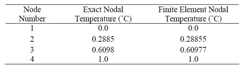
Table 1. Comparison of exact nodal temperature (˚C) and finite element nodal temperature (˚C).
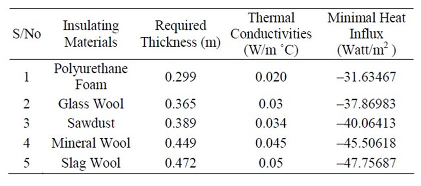
Table 2. Required insulating material thickness for spherical storage vessels for LNG.
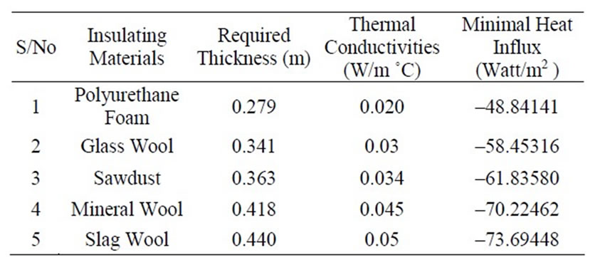
Table 3. Required insulating material thickness for spherical storage vessels for H2(l).
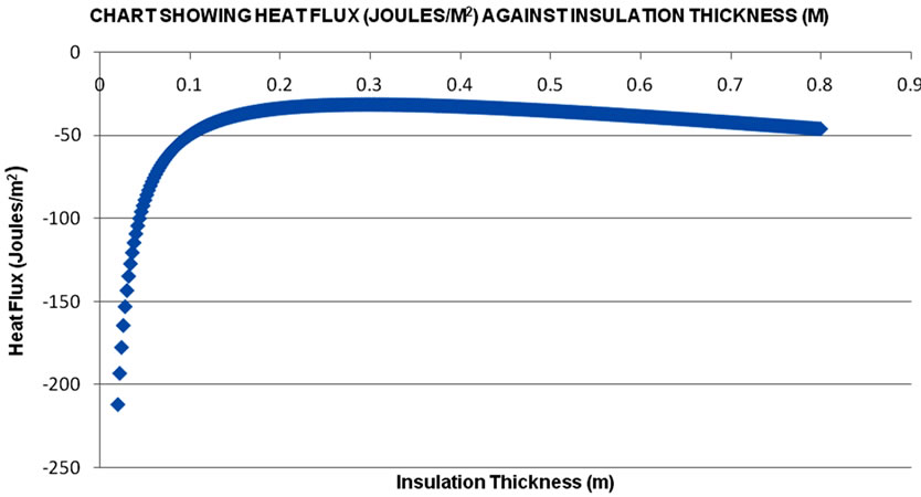
Figure 2. Shows values of heat flux into the stored product as the thickness of insulating material increases.
5. Conclusions and Recommendations
The usefulness of finite element method in the determination of various insulations thicknesses for insulating spherical storage vessels for Cryogenic products cannot be overemphasized. Using finite element method, the temperatures at nodes are determined together with their respective heat fluxes. During computer simulation, the insulation thickness is increased until the heat flux into the stored product is minimal. This is to reduce the boil off and to maintain the storage conditions of cryogenic products. The insulation thickness at which this happens is termed as “critical thicknesses”. In the computer simulation, different insulating material gives different minimal heat influx into the stored products and with varying insulating material thicknesses as showing in the tables. On this note, design engineer needs to have good knowledge of finite element method to be able to predict the performance of selected insulating material for his design.
To the best knowledge of this author there are no existing codes and standards for the selection and determination of insulation thicknesses for stored cryogenic products.
REFERENCES
- Sandia Report, “Guidance on Risk Analysis and Safety Implications of a Large Liquefied Natural Gas (LNG) Spill over Water,” 2004. http://www.fossil.energy.gov/programs/oilgas/storage/lng/sandia_lng_1204.pdf
- S. M. Aceves, et al., “Insulated Pressure Vessels for Vehicular Hydrogen Storage: Analysis and Performance Evaluation,” American Society of Mechanical Engineers International Congress and Exposition, New York, 11-16 November 2001.
- E. Coussedière, C. Gauthier and N. Edjtemai, “A Seismic Post Elastic Behaviour of Spherical Tanks,” Technip France, 2001. www.dynalook.com/european-conf-2001/59.pdf/view
- M. Huther, F. Benoit and J. Poudret, “Fatigue Analysis Method for LNG Membrane Tank Details” The Society of Naval Architects and Marine Engineers, One World Trade Cenler, Suite 1369, New York, 20 October 1981.
- S. M. Arnold, B. A. Bednarcyka, C. S. Collier and P. W. Yarrington, “Spherical Cryogenic Hydrogen Tank Preliminary Design Trade Studies,” 48th Structures, Structural Dynamics, and Materials Conference Cosponsored, Hawaii, 23-26 April 2007.
- S. K. Mital, J. Z. Gyekenyesi, S. M. Arnold, R. M. Sullivan, J. M. Manderscheid and P. L. N. Murthy, “Review of Current State of the Art and Key Design Issues with Potential Solutions for Liquid Hydrogen Cryogenic Storage Tank Structures for Aircraft Applications,” Aerospace Engineering Papers, NASA, 2006.