Engineering
Vol. 2 No. 10 (2010) , Article ID: 3179 , 9 pages DOI:10.4236/eng.2010.210102
Optimization of Surface Milling of Hardened AISI4340 Steel with Minimal Fluid Application Using a High Velocity Narrow Pulsing Jet of Cutting Fluid
1School of Mechanical Sciences, Karunya University, Coimbatore, Tamilnadu, India
2Department of Mechanical Engineering, IIT Madras, Chennai, India
E-mail: leodevwins@gmail.com, varadarajan_as@yahoo.co.in
Received July 26, 2010; revised September 28, 2010; accepted October 13, 2010
Keywords: Environment friendly, Pulsed jet, Minimal cutting fluid application
ABSTRACT
Surface milling of hardened steel is carried out with copious supply of cutting fluid and is obviously associated with problems related to procurement and storage of cutting fluid. The disposal of cutting fluid has to comply with environmental legislation such as OSHA regulations. The present investigation proposes an environment friendly minimal pulsed jet cutting fluid application scheme for surface milling of AISI4340 steel with a hardness of 45 HRC using commercially available carbide tools. This scheme can be implemented as such on the shop floor with out the need for any major alternations on the existing facilities and it was observed that the new scheme is not only environment friendly but also provided better cutting performance when compared to conventional wet milling which requires copious supply of cutting fluid.
1. Introduction
Conventional surface milling of hardened steel needs application of large quantities of cutting fluid. Procurement, storage and disposal of cutting fluid incur expenses and large scale use of cutting fluid causes serious environmental and health hazards on the shop floor. Apart from the fact that it gives a foul smell, disposal of cutting fluid is a problem and one has to comply with environmental legislation.
In this context, dry milling is a logical alternative which is totally free from the problems associated with storage and disposal of cutting fluid. But it is difficult to implement on the existing shop floor as it needs ultra hard cutting tools and extremely rigid machine tools. Ultra hard cutting tools may be introduced but the existing machine tools may not be rigid enough to support dry hard milling. In this context the best alternative is to introduce pseudo dry milling or milling with minimal fluid application. In this method, extremely small quantity of cutting fluid is introduced at high velocity (70 m/s) in the form of tiny droplets at critical zones so that for all practical purposes it resembles dry machining. [1-4].
It is reported that minimal cutting fluid application can improve cutting performance during turning [5]. Some fundamental work is reported in the field of fluid minimization during turning. But very less work is reported in the area of fluid minimization during milling [6-8]. The present work aims at a systematic investigation on the viability of cutting fluid minimization during surface milling of AISI 4340 steel with a hardness of 45 HRC by developing a fluid application system that can deliver a high velocity narrow pulsed jet of cutting fluid through fluid application nozzles that can be located with the help of fixtures so that cutting fluid particles can reach critical zones and offer better cooling and lubrication. The most important aspect of this scheme is that it can be easily implemented on the shop floor and offers better cutting performance when compared to conventional wet milling while using very small quantities of cutting fluid (about 5-15 ml/min).
1.1. Selection of Work Material
A through hardenable AISI4340 steel was selected as work material. It was hardened to 45 HRC by heat treatment. It is a general purpose steel having a wide range of applications in automobile and allied industries by virtue of its good hardenability. Plates of 125 mm length, 75 mm breadth and 20 mm thickness were used for the present investigation. The composition of the work material is shown in Table 1.
1.2. Selection of Cutting Tool
Carbide inserts with the specification AXMT 0903 PER -EML TT8020 of TaeguTec was used in the investigation along with a tool holder with the specification TE90AX 220-09-L.
1.3. Formulation of Cutting Fluid
Since the quantity of cutting fluid used is extremely small, a specially formulated cutting fluid was employed in this investigation. The base was a commercially available mineral oil and the formulation contained other ingredients [9]. It acted as oil in water emulsion.
1.4. Fluid Application System
A special fluid application system was developed for this purpose [1]. It consists of a P-4 fuel pump (Bosch make) coupled to an infinitely variable electric drive. An injector nozzle of single hole type with a specification DN0SD151 with a spray angle of 0˚ was used in the investigation. The fluid application system facilitated independent variation of pressure at fluid injector (P), frequency of pulsing (F) and the rate of fluid application (Q). The system can deliver cutting fluid through four outlets simultaneously so that cutting fluid could be applied to more than one location or more than one machine tool at the same time. By selecting proper settings, the rate of fluid application could be made as small as 0.25 ml/min. The frequency of pulsing is determined by the speed of rotation of the DC variable speed motor that drives the fluid pump.
The fluid applicator delivers cutting fluid in the form of pulsed spray at the rate of one pulse per revolution. This facility enables application of less amount of cutting
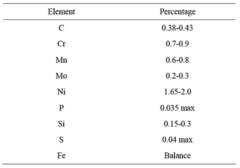
Table 1. Chemical composition of work material.
fluid per pulse. The quantity per pulse is adjusted by a plunger with helical groove arrangement which is present in the fluid pump which can be rotated about its axis and the angle through which the plunger is rotated determines the quantity of fluid delivered per stroke. In this system, it is possible to deliver cutting fluid at the same rate of fluid application with different frequencies of pulsing. For example, if Q is the rate of fluid application in ml/min and F is the frequency of pulsing in pulses/min, fluid applied per pulse is given by Q/F. Pulsing jet aids in fluid minimization without compromising the velocity of individual particles as the pressure at the fluid injector remains constant. By varying the frequency, the rate of fluid delivered per pulse can be controlled. For example if Q is 1 ml/min and F is 1000 pulses/min and the pressure at the fluid injector is set at 100 bar, then fluid delivered per pulse is equal to 1/1000 = 0.001 ml while the velocity of the individual fluid particles will be approximately equal to 70 m/sec [10,11].
A schematic view of the fluid applicator is shown in Figure 1. Special fixtures were designed so that the injector nozzle could be located in any desired position without interfering the tool or work during actual cutting.
2. Experimentation
The minimal pulsed jet fluid applicator (MPFA) developed in the Centre for Research in Design and Manufacturing Engineering (CRDM) of Karunya University for carrying out this research work was characterized by the following fluid application parameters which can be varied independently.
1) Pressure at the fluid injector (P) in bar.
2) Frequency of pulsing (F) in pulses/min.
3) Rate of fluid application (Q) in ml/min.
4) Mode of fluid application (N).
It was decided to explore the relative significance of these fluid application parameters along with one cutting fluid parameter namely the composition of the cutting fluid on the cutting performance. The fluid application and fluid composition parameters were varied at two levels as summarized in Table 2.
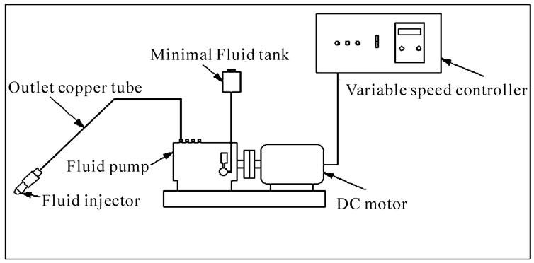
Figure 1. Schematic view of the minimal fluid applicator.
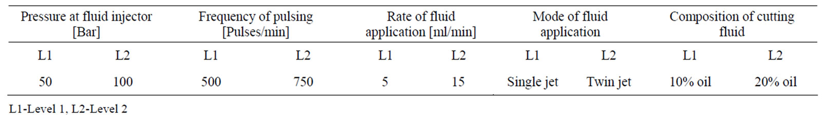
Table 2. Input parameters and their levels.
In order to ensure better penetration of cutting fluid in to the rake face, an attempt was made to make use of more than one fluid jet. Accordingly a single jet configuration as in Figure 2(a) that corresponds to level-1 and a twin jet configuration as in Figure 2(b) which corresponds to level-2 were used in this investigation.
Two compositions of cutting fluid were considered in this investigation. The first composition contained 10% oil and the rest water (level-1) and the second contained 20% oil and the rest water (level-2).
2.1. Mode of Analysis
Selection of the operating parameters for optimum performance was planned using Response Table Methodology [12]. A set of levels of operating parameters are to be determined to obtain minimum surface roughness, minimum flank wear and minimum cutting force. These operating parameters are to be used to compare the relative advantage of this method with respect to conventional wet milling and dry milling for the same tool-work machine tool system with constant cutting parameters such as cutting speed, feed and depth of cut which are shown in Table 3.
An 8 run experiment was designed based on Taguchi’s techniques [12] and the design matrix is shown in Table 4. The experiments were conducted with two replications. Surface roughness, flank wear and main cutting force were considered as the performance parameters. With optimum cutting performance as the basis, it was sought to determine 1) the level of the rate of fluid application 2) the level of frequency of pulsing 3) the level of pressure at the fluid injector 4) the level of composition of the cutting fluid and 5) the level of number of fluid jets to be employed.
2.2. Experimental Details
Experiments were carried out on an HMT (model: FN1U) milling machine. A Kistler dynamometer was used for measuring cutting force. Surface roughness was measured using a stylus type Perthometer (Mahr make), flank wear measurement was done using a tool maker’s microscope. The cutting speed, feed and depth of cut were set in the semi finish milling range for the tool-work combinations.
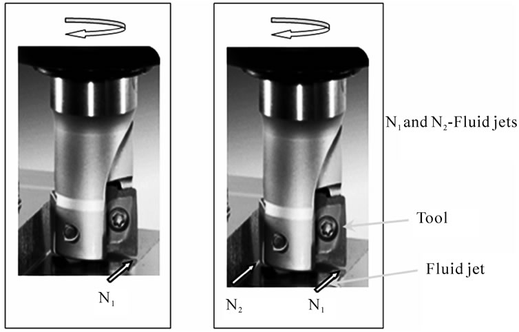
Figure 2. Mode of fluid application (Single jet & twin jet).

Table 3. Parameters kept constant and their values.
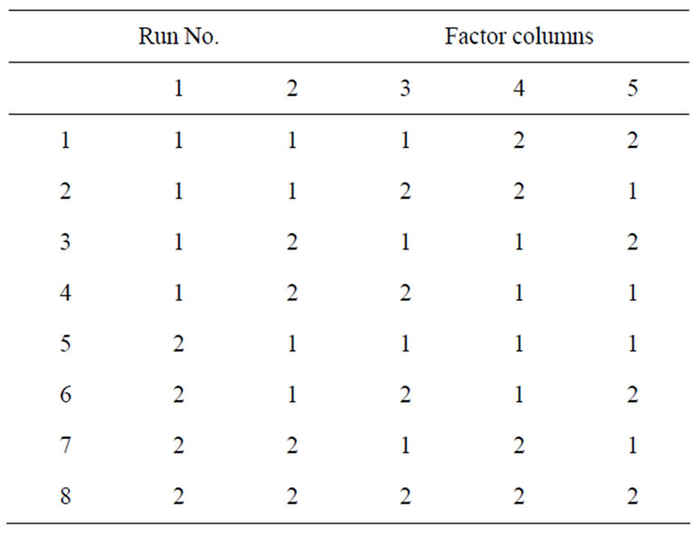
Table 4. Basic design matrix for eight run two level experiment with five factors.
3. Results and Discussion
Figure 3 presents the relative significance of the operating parameters (fluid application as well as the cutting fluid parameters) on attainable surface finish. The rela-
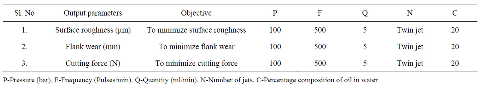
Table 5. Summary of operating parameters for optimum performance.
tive significance of operating parameters on flank wear is shown in Figure 4 and the relative significance of the operating parameters on cutting force is presented in Figure 5. ANOVA analysis was also carried out using Qualitek-4 software to find out the percentage influence of individual parameters on surface roughness, flank wear and cutting force. From the ANOVA results, it was evident that pressure at the fluid injector forms the most significant parameter influencing the output parameters. It was also found that the interaction effects were not significant. The percentage of significance of pressure at the fluid injector on surface roughness, flank wear and cutting force were 54.203, 58.962, and 72.99 respectively. The results of the analysis which led to a set of levels of fluid application as well as cutting fluid parameters to minimize surface roughness, flank wear and cutting force are summarized in Table 5. The following parameter wise discussion is based on the results presented in Table 5.
3.1. Pressure at the Fluid Injector
The pressure at the fluid injector kept at level-2(100 bar) favored lower flank wear and better surface finish. The penetration power of the fluid droplet is directly proportional to the exit velocity (approximately 70 m/s) [3] and the velocity varies as a function of the square root of the injection pressure [11] where as the size of the individual droplets is inversely proportional to the exit velocity [13]. The cutting force is directly related to the chip friction on the rake face. Any attempt to reduce friction on the rake face can bring forth lower cutting force, lower energy consumption, better surface finish and lower flank wear. When the pressure at the fluid injector is high, better penetration will be facilitated leading to better lubrication at the contact surfaces.
3.2. Mode of Fluid Application
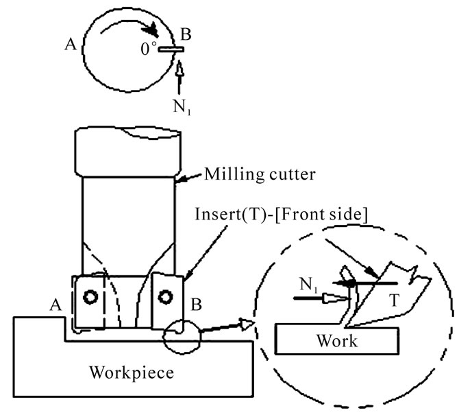
When the tool insert T is in location B as shown in Figure 6(a), the direction of impingement of the fluid droplets from nozzle N1 is opposite to the direction of movement of the tool insert T and the fluid drops fall on the back side of the chip.
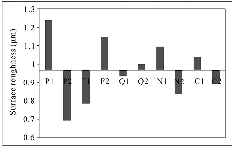
Figure 3. Relative significance of levels of operating parameters on surface roughness.
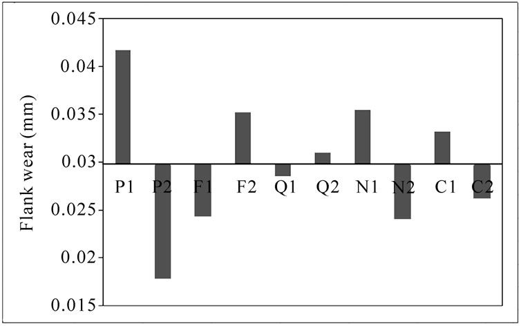
Figure 4. Relative significance of levels of operating parameters on flank wear.
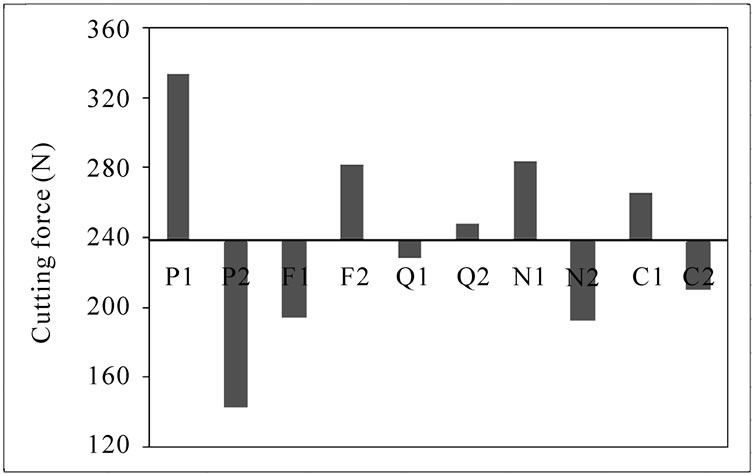
Figure 5. Relative significance of levels of operating parameters on cutting force.
When the cutter rotates through 180° and assumes the location A, the scenario is as indicated in the Figure 6(b). In this case, the direction of impingement of fluid droplets from the nozzle N2 is in the same direction as the direction of movement of tool insert T and the fluid droplets fall on the tool-work interface.
In the present investigation two configurations were used. The configuration as shown in Figure 6(b) forms level-1 and that in Figure 6(c) forms level-2 for the mode of fluid application as presented in Table 2. It was observed that the twin jet configuration as shown in Figure 6(c) gave better cutting performance when compared to the single jet configuration.
The single jet configuration was selected as level-1 based on earlier work and results [10] in which mention is made about the advantages of minimal fluid application on the tool-work interface during hard turning.
When a configuration as in Figure 6(c) is selected, fluid droplets are applied both on the back side of the chip as in Figure 6(a) and on the tool-work interface as in Figure 6(b). When cutting fluid is applied on the back side of the chip, the fluid particles owing to their high velocity tend to adhere to the back side of the chip. These droplets evaporate taking the latent heat of vaporization from the chip. Figure 7 shows the cooling of the back side of the chip which leads to its contraction where as the chip surface in contact with the rake face is hot and tends to elongate.
This leads to the curling of the chip away from the tool rake face resulting in the reduction of tool-chip contact length. Reduction in tool-chip contact length brings forth lower cutting force; lower flank wear and hence improved surface finish [10,14].
A chemical phenomenon can also occur at the tip of the micro cracks that formed on the back side of the chip. High velocity fluid droplets can penetrate on the back side of the chip and reach the tip of the micro cracks and stick on the surface owing to their high velocity. In the absence of cutting fluid, the nascent surface at the crack tip can coalesce due to the formation of micro weldments. The micro weldments can strengthen the back side of the chip thereby reducing the tendency of the chip to bend away from the rake face. But when a fluid droplet is present at the crack tip, it dopes the nascent surface and acts as a dielectric preventing the formation of micro weldments. This leads to the weakening of the back side of the chip and the chip tends to bend backwards, i.e., away from the rake face resulting in the reduction in tool-chip contact length and hence lower cutting force [15]. Weakening of the back side also leads to its ultimate fracture resulting in the formation of fragmented chips that can be handled easily.
When cutting fluid is applied through the nozzle N2,
 (a)
(a) (b)
(b)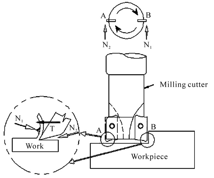 (c)
(c)
Figure 6. Location of fluid jet(s) (a) N₁ in single jet configuration; (b) N₂ in single jet configuration; (c) N₁ and N₂ in the twin jet configuration.
 (a) (b)
Figure 7. Effect of cooling the back side of the chip, (a) cooling of the back side of the chip; (b) no supply of cutting fluid.
the high velocity fluid droplets can enter the tool-work interface as in Figure 6(b) and finally can make their way to the tool-chip interface as shown in Figure 8 through the micro cracks near the root of the chip.
These fluid particles provide rake face lubrication by forming a film of lubricant that adheres strongly to the rake face of the tool which reduces friction and hence the cutting force. The extreme pressure that exists at the tool-chip interface prevents the easy entry of cutting fluid particles into the tool-chip interface. But when cutting fluid is applied at the tool-work interface, some cutting fluid particles can enter into the tool-chip interface through the small capillaries that exist at the root of the chip(Figure 8) which can permit passage of cutting fluid particles of smaller size if they posses sufficient kinetic energy by virtue of their high velocities. There is also a possibility of formation of a complex compound on the tool-chip interface which offers very low shear force and act as a lubricant owing to the extreme thermal conditions that exist in the rake face as proposed by Varadarajan et al. [9]. Moreover the presence of cutting fluid at the tool -chip interface can act as a dielectric preventing the intensity of surface interaction between the chip and the tool thereby transforming the condition in the region OA in Figure 8 from sticking to one of sliding, leading to reduction in cutting force.
There is of course the possibility of burning of cutting fluid droplets at the tool-chip interface due to the severe thermal conditions that exist there. Even the burnt out fluid debris can act as a dielectric preventing inter molecular as well as inter atomic interaction between the tool and the chip (Figure 9) thereby preventing sticking of the chip on the rake face and this leads to reduction in cutting force. Moreover the fluid particles falling near the root of the chip can cause weakening of the cutting zone by creating zones of weakness on the work material and at the front side of the chip due to the embrittlement action of the cutting fluid. This action is based on Rebinder effect and involves micro cracks formation and healing [16]. Adsorbed film/burned debris of cutting fluid prevents closing of micro cracks. Each micro crack near the root of the chip act as a stress concentrator and
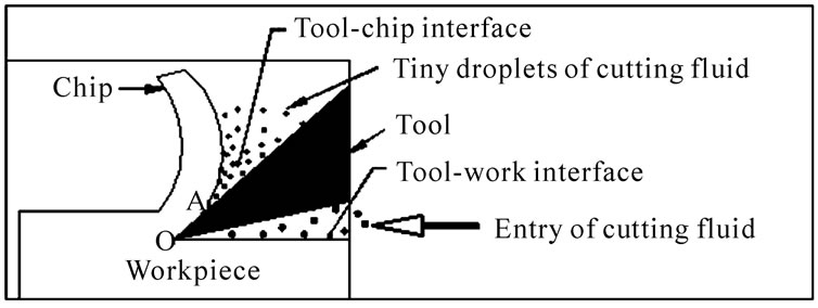
Figure 8. Passage of cutting fluid droplets into the tool-chip interface from tool-work interface.
 (a) (b)
Figure 9. Functioning of cutting fluid as a dielectric, (a) nascent chip surface tends to stick to the tool surface; (b) burned debris prevents surface interactions.
the energy needed for cutting gets reduced. In other words, penetration of foreign atoms from the cutting fluid decomposition produces an embrittlement effect near the root of the chip similar to hydrogen embrittlement which reduces the energy needed for cutting the material.
When cutting fluid is applied with two nozzles, performance improvement through reduction of cutting force is possible through two mechanisms namely reduction of tool-chip contact length and better rake face lubrication whereas when a single nozzle is employed only one mechanism namely reduction in tool-chip contact length is in operation. Hence a twin jet configuration can offer better cutting performance when compared to single jet configuration owing to the dual mechanisms of chip curl and rake face lubrication.
3.3. Rate of Application
It is observed that the rate of fluid application at low level is advantageous in terms of better surface finish, lower flank wear and lower cutting force. According to the empirical relationship developed by Hiroyasu and Kadota [13], the mean diameter D for a droplet size of cutting fluid injection is given by
D = K(ΔP)-0.135 ρ0.121V0.131
where ΔP is the mean pressure drop, ρ is the density of the medium in which injection of fluid takes place, V is the quantity of fluid delivered per pulse and K is a constant. With lower delivery rates, the size of individual droplets decreases. As explained earlier, these tiny droplets provide better lubrication leading to lower cutting force, lower flank wear and better surface finish. Moreover the rate of fluid application can be kept at lower level (5 ml/min) which will also ensure efficient evaporative heat transfer, lower rates of fluid consumption and reduced mist formation that leads to a green environment on the shop floor.
During conventional wet turning, the quantity of heat extracted by convective heat transfer is given by Q = mCpΔT where Q is the heat quantity in K cal, m is the mass of cutting fluid, Cp is the specific heat capacity and ΔT is the temperature reduction brought about.
However, during minimal fluid application cooling occurs due to both convective and evaporative heat transfer. The evaporative heat transfer is facilitated by the increase in surface area caused by atomization and the quantity of heat removed is given byQ1 = mCpΔT + mL where m, Cp and ΔT have the same notation as mentioned before. m is the mass of the fluid evaporated and L is the evaporation enthalpy. In the case of water the evaporation enthalpy is 2260 kJ/kg and in the case of mineral oil is about 210 kJ/kg. The specific heat capacity Cp for water is 4.2 kJ/kg K˚ and that for mineral oil is 1.9 kJ/kg K˚. Since the evaporation enthalpy of water is very high, evaporation of even a very small quantity of water is sufficient to create better cooling. Moreover the cutting fluid droplets by virtue of their high velocity can puncture the blanket of vapor and reach the interfaces facilitating more efficient heat transfer which is not possible in conventional wet milling where the adherent film of lubricant retards the heat transfer.
Hence when the rate of fluid application is low, smaller will be the droplet sizes, which leads to increased surface area to facilitate evaporative heat transfer and high individual droplet velocities facilitate better penetration of fluid particles into the tool-chip interface.
3.4. Composition
It is seen that composition of cutting fluid comprising of 20% oil and the rest water corresponding to level-2 offered improved cutting performance when compared to a composition with 10% oil. During machining, cutting fluid acts as a coolant and as a lubricant. In case of oil in water emulsion as used in this investigation, water acts as a coolant and oil acts as a lubricant. During minimal fluid application, very small quantity of cutting fluid is expected to perform the dual functions of cooling and lubrication. It appears that a composition consisting of 10% oil is too lean to provide effective rake face lubrication at the tool-chip interface. A certain minimum quantity of lubrication must be present in the cutting fluid to compensate for the possible losses as the fluid reaches the tool-chip interface through the tool-work interface.
3.5. Frequency of Pulsing
It is observed that frequency of pulsing of fluid application at low level favored better cutting performance. It is reported that the frictional forces between two sliding surfaces can be reduced considerably by rapidly fluctuating the width of the lubricant filled gap separating them [17].
When a pulsing jet is used, the width of the lubricant filled gap between the tool rake face and the chip fluctuates with a frequency equal to the frequency of pulsing of the fluid jet. The width will be maximum when the fluid slug falls at the gap and will be minimum when no particles fall on the gap during the pulsing cycle. This process continues as the fluid particles fall in the gap between the chip and the tool intermittently. When the frequency of pulsing (F) is 750 pulses/min, the quantity of fluid delivered per pulse is very less when compared with the frequency of pulsing of 500 pulses/min for any fixed rate of fluid application. Hence the fluctuation in the width of the liquid film between the tool and the chip is less appreciable when the frequency of pulsing is 750 pulses/min when compared to that at a frequency of 500 pulses/min. A minimum quantity of cutting fluid should be delivered per pulse to get an appreciable fluctuation in the width. This leads to presence of fresh fluid droplets in to the tool-chip interface unlike in the case where a stagnant layer of cutting fluid is present when a continuous jet is employed [18]. The presence of fresh fluid droplets facilitates better filling of the gap on the tool -chip interface thereby providing better lubrication and enhanced cooling as the droplets evaporate.
Moreover, when the frequency of pulsing is very high, the individual particles will be small and may lack in kinetic energy to penetrate in to the tool-chip interface. This leads to less fluid particles reaching the rake face and hence less efficient rake face lubrication. It is also to be noted that the pulsing nature of the fluid delivery vanishes when the frequency of pulsing is very high and the fluid delivery tends to resemble a continuous jet, devoid of all the aforesaid advantages claimed for a pulsing jet.
3.6. Comparison of Flank Wear
Average flank wear was determined during dry, wet and minimal fluid application, keeping the cutting speed, feed and depth of cut at 45 m/min, 0.14 mm/tooth and 0.4 mm respectively. The flank wear was 0.127 mm during dry milling 0.031 mm during conventional wet mill-
 (a)
(a)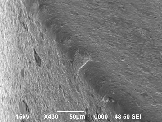 (b)
(b) (c)
(c)
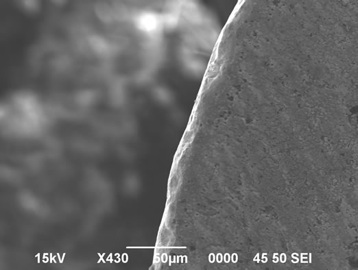
Figure 10. SEM photographs on comparison of worn out insert edges during dry, wet and minimal fluid application, (a) dry milling; (b) wet milling; (c) milling with minimal fluid application. Cutting speed-45 m/min, Feed-0.14 mm/tooth, Depth of cut-0.4 mm, Cutting time-120 sec.
ing and 0.018 mm during optimized milling with minimal fluid application for a cutting time of 120 seconds. SEM photographs of tool flank wear during dry milling, conventional wet milling and milling with minimal fluid application are presented in Figures 10(a), (b) and (c) respectively. It is observed that flank wear is minimum during milling with minimal fluid application in the optimized mode. Lower flank wear during minimal fluid application is attributed to better rake face lubrication and lower tool-chip contact length and better heat transfer due to evaporative cooling. The comparison of results of optimized milling with minimal fluid application with dry milling and conventional wet milling is presented in Table 6 from which it is clear that milling with minimal fluid application can offer improved surface finish, lower flank wear and lower cutting force when compared to dry milling and conventional wet milling.
Figures 11 to 13 presents a comparison of surface roughness, flank wear and cutting force during dry milling, wet milling and milling with minimal fluid application. It can be seen that milling with minimal fluid application with twin-jet configuration can bring forth better surface finish, lower flank wear and lower cutting force when compared to that during conventional wet milling and pure dry milling.
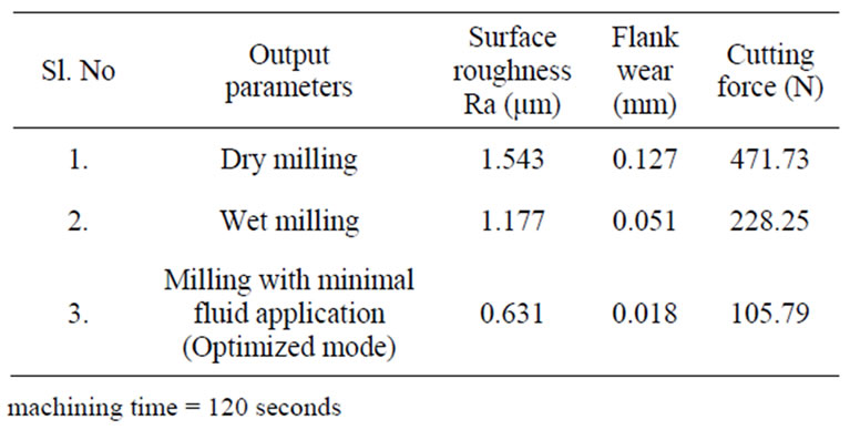
Table 6. Comparison of output parameters during wet, dry and milling with minimal fluid application.

Figure 11. Comparison of surface roughness (Ra).
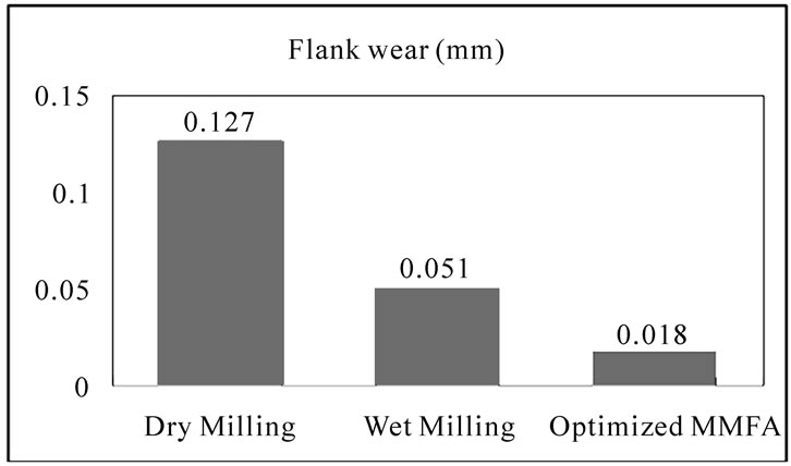
Figure 12. Comparison of flank wear.

Figure 13. Comparison of cutting force.
4. Conclusions
It is observed that the fluid application parameters namely pressure of fluid injection, frequency of pulsing, direction of fluid application, composition and rate of fluid application have their own influence on the cutting performance during surface milling of hardened AISI4340 steel.
Results in this work indicated that milling with pulsed jet minimal fluid application holds promise for the development of a commercial environment friendly pulsed jet fluid application scheme with particular reference to surface milling of hardened steel.
5. Acknowledgements
The authors thank the authorities of the Centre for Research in Design and Manufacturing of the Karunya University for facilitating this project and M/s Taugetec India (P) Ltd. for supplying cutting tools at concessional rates.
6. REFERENCES
- A. S Varadarajan, P. K. Philip and B. Ramamoorthy, “Investigations on Hard Turning with Minimal Cutting Fluid Application(HTMF) and Its Comparison with Dry and Wet Turning,” International Journal of Machine Tool and Manufacture, Vol. 42, No. 2, 2001, pp. 193-200.
- A. S. Varadarajan, P. K. Philip and B. Ramamoorthy, “Neural Network Assisted Performance Prediction in Hard Turning with Minimal Quantities of Cooling Lubricants,” Proceedings of the 14th International Conference, CAD/CAM, Robotics and Factories of the Future, PSG College of Technology, Coimbatore, India, 1998, pp. 654 -658.
- A. S. Varadarajan, P. K. Philip and B. Ramamoorthy, “Investigations on Hard Turning with Minimal Pulsed jet of Cutting Fluid,” Proceedings of the International Seminar on Manufacturing Technology beyond 2000, Bangalore, India, 1999, pp. 173-179.
- A. Attansio, M. Gelfi, C. Giardimi and C. Remino, “Minimal Quantity Lubrication in Turning: Effect on tool wear,” International Journal of Wear, Vol. 260, No. 3, 2006, pp. 333-338.
- A. S. Varadarajan, P. K. Philip and B. Ramamoorthy, “Optimization of Operating Parameters for the Cutting Performance during Hard Turning with Minimal Cutting Fluid,” Proceedings of the International Conference on Intelligent, Flexible, Autonomous Manufacturing Systems, Coimbatore, India, 2000, pp. 717-725.
- A. Raj, K. L. D. Wins, R. Gnanadurai and A. S Varadarajan, “Investigations on Hard Milling with Minimal Fluid Application,” International Conference on Frontiers in Design and Manufacturing, Karunya University, Coimbatore, 2008, pp. 183-187.
- T. Thepsonthi, M. Hamdi and K. Mitsui, “Investigation into Minimal-Cutting Fluid Application in High-Speed Milling of Hardened Steel Using Carbide Mills,” International Journal of Machine Tools and Manufacture, Vol. 49, No. 2, 2009, pp. 156-162.
- M. Rahman, A. S. Kumar and M. U. Salam, “Experimental Evaluation on the Effect of Minimal Quantities of Lubricant in Milling,” International Journal of Machine Tools & Manufacture, Vol. 42, No. 5, 2002, pp. 539-547.
- A. S. Varadarajan, B. Ramamoorthy and P. K. Philip, “Formulation of a Cutting Fluid for Hard Turning with Minimal Fluid Application,” 20th AIMTDR conference at Birla institute of Technology Ranchi, India, 2002, pp. 89 -95.
- P. K. Philip, A. S Varadarajan and B. Ramamoorthy, “Influence of Cutting Fluid Composition and Delivery Variables on Performance in Hard Turning Using Minimal Fluid in Pulsed Jet Form,” Journal of the Institution of Engineers (India), Vol. 82, No. 3, 2001, pp. 12-19.
- J. B. Heywood, “Internal Combustion Engine Fundamentals,” McGraw-Hill, New York, 1996.
- R. H. Lochner and J. E. Matar, “Design for Quality,” Chapman and Hall, London, 1990, pp. 77-95.
- Hiroyasu and T. Kadota, “Fuel Drop Size Distribution in Diesel Combustion Chamber,” SAE paper 740715, SAE Transactions, Vol. 83, 1974, pp. 715-721.
- L. De Chiffre, “Function of Cutting Fluids in Machining,” Journal of the Society of Tribologists and Lubrication Engineers, Vol. 44, No. 6, June 1998, p. 514.
- Ball, “A Survey of Metal Working Fluid Mist in Manufacturing Plants,” Journal of the Tribologists and Lubrication engineers, Vol. 53, No. 9, 1997, p. 18.
- V. P. Astakhov, “Metal Cutting Theory Foundations of Near-Dry (MQL) Machining,” International Journal of Machining and Machinability of Materials, Vol. 7, No. 1/2, 2010, pp. 1-16.
- U. Landman, “"FRUSTRATED" lubricant molecules offer new strategy for reducing friction in mechanical devices,” Georgia Tech – Research news. http://gtresearchnews.
- gatech.edu/newsrelease/FRICTION.html
- R. Alexender, A. S. Varadarajan and P. K. Philip, “Hard Turning with Minimum Cutting Fluid – A Viable Green Alternative on the Shop Floor,” Proceedings of the 18th All India Manufacturing Technology Design and Research Conference, vol. 1, Kharagpur, 1998, pp. 183- 187.
- G. Boothroyd and W. A. Knight, “Fundamentals of Machining and Machine tools,” 3rd Edititon, CRC Taylor& Francis UK, 2006, pp. 69-100.