Wireless Engineering and Technology
Vol.4 No.2(2013), Article ID:29804,4 pages DOI:10.4236/wet.2013.42015
Very Compact Bandstop Filters Based on Miniaturized Complementary Metamaterial Resonators
![]()
1European University of Bretagne, National Institute of Applied Science of Rennes, Institute of Electronic and Telecommunication of Rennes, Rennes, France; 2Moroccan School of Engineering Science of Rabat, Rabat, Morocco.
Email: Hicham3076@gmail.com
Copyright © 2013 Hicham Lalj et al. This is an open access article distributed under the Creative Commons Attribution License, which permits unrestricted use, distribution, and reproduction in any medium, provided the original work is properly cited.
Received February 21st, 2012; revised September 18th, 2012; accepted October 3rd, 2012
Keywords: Metamaterials; Bandstop Filter; Complementary Split Ring Resonators (CSRRs)
ABSTRACT
In this paper, a design of very compact microstrip bandstop filters based on complementary split ring resonators (CSRRs) is proposed. Two techniques of metamaterial miniaturization are used to optimize the physical and electrical size of the CSRR. The bandstop filter is produced by an array of miniaturized loaded CSRRs etched on the center line of a microstrip. The size of the proposed filter, is as small as 0.58 cm2, and its electrical length is very small with only 0.08 λ0), compared to a conventional bandstop filter, a miniaturization of a factor 5 while the bandstop performance is maintained. A very good agreement obtained between the measurement and the simulation results.
1. Introduction
Many modern telecommunications systems, such as the embedded systems, systems of mobile phone and wireless communication, use filters; many conventional filter designs has reached their technologically defined limits. To satisfy the increasing demand for high performance, circuit integration and reduced size, alternative concepts have to be explored [1].
In recent years, left-handed Metamaterials have attracted considerable interest of scientists and engineers working in the field of microwave technology. These Metamaterials exhibit both a negative permittivity and permeability which result in a negative index of refraction, a property not available within any natural material [2-4]. From duality arguments, it has been shown that negative permittivity media can also be generated by means of a resonant element, namely the complementary split ring resonator (CSRR) introduced by Falcone et al. in 2004 [5]. These resonators can be considered as quasilumped elements and are, therefore, also very interesting for the miniaturization of planar microwave devices such as filters and diplexers, or for improving their performances.
In previous research of some of the authors, SRRs and CSRRs have been successfully applied to the design of microwave filters [6,7].
The aim of this paper is to apply a bandstop filter synthesis proposed in the literature [4] based on CSRRs, and two techniques of Metamaterials miniaturization [8-10], to design a very compact microwave bandstop filter.
In Section 2, we propose a design of conventional bandstop filter based on CSRRs etched on the center line of a microstrip. In Section 3, I will describe how to obtain a reduction of the filter size by the optimization of electrical and physical CSRR size. Finally, in Section 4, the obtained calculated results are discussed and compared with measurements.
2. Bandstop Filter Design
A conventional bandstop filter based on a 50 Ω line and the CSRR etched in the conductor strip [4] is designed in the microstrip technology. This filter is considered as reference of comparison with the realised miniaturized filters.
CSRR is dual counterparts of SRR. Therefore a dual electromagnetic behaviour for them is expected according to the duality theorem. The incident electric field needs to be polarized in the axial direction of the resonator. In this way, CSRRs are etched on center line of the microstrip technology.
This arrangement makes sure that the CSRRs are properly exited by the electric field applied parallel to the ring axis.
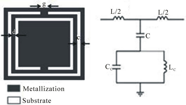
The CSRR topology and equivalent circuit model are illustrated in Figure 1. The CSRR unit cell was designed to operate around 5.70 GHz. The geometry of the cell is as follows: c = d = 0.3 mm, g = 0.6 mm and the global size is 7.4 mm × 3 mm.
The substrate used is a RT/Duroid having the following characteristics (relative permittivity εr = 2.2, loss tangent tg(φ) = 0.0001 and thickness h = 0.8 mm).
The resonator is simulated by using a commercially available 3D full-wave solver (Ansoft HFSS).
Figure 2 shows the [S] parameters simulated results. It shows a rejected frequency band around the designed frequency of the CSRR resonator explained by a transmission of about −25 dB.
Figure 3 shows a conventional bandstop filter design; it consists of 3 rings CSRRs. Our simulation results show that three rings could provide significant improvement. Further increase of rings would have just an increase of reject level.
Figure 4 presents the conventional bandstop filter simulated results. It has a central frequency of 5.7 GHz and a rejection band as wide as 1.2 GHz with 20% fractional bandwidth. A deep rejection band (S21 = −40 dB) is obtained in the designed frequency with low return loss.
Figure 5 shows the simulated group delay. It presents a very small variation in the operating frequency (<1 ns).
The overall area for the filter is 0.67 cm2, and the electrical length of device, excluding access lines, is 0.44 λ0.
 (a) (b)
Figure 1. (a) CSRR particle with relevant dimensions; (b) CSRR microstrip line equivalent circuit model.
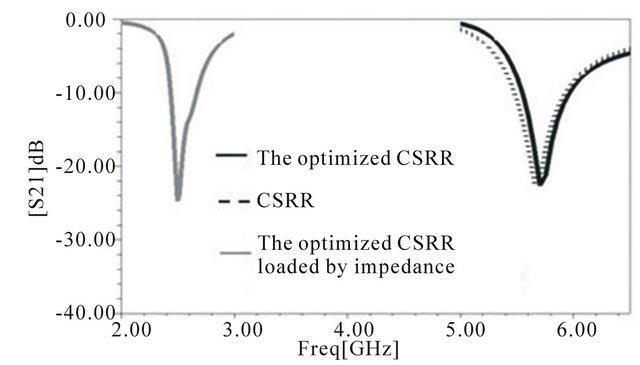
Figure 2. Simulated S21 parameters for different CSRRs structures.
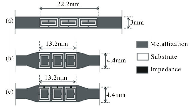
Figure 3. (a) Design of conventional bandstop filter based on CSRRs; (b) Design of proposed bandstop filter based on optimized CSRRs; (c) Design of bandstop filter based on optimized CSRRs loaded by an impedance.
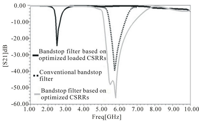
Figure 4. Simulated S21 parameters for different bandstop filters structures.
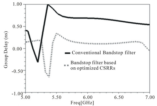
Figure 5. Simulated group delay for bandstop filters.
3. Bandstop Filter Miniaturization
To reduce the bandstop filter size whilst sustaining the filter bandstop performances, two techniques of metamaterial miniaturization are utilized. The first one is based on the dimensions optimization, and the second is based on the increasing of the equivalent distributed capacitance.
The first technique consists in reducing the physical size of the resonator, knowing that the CSRR resonant frequency depends on their dimensions [2,5].
The optimized geometry of the CSRR, while having the same metamaterial phenomenon around 5.7 GHz, is as follows: c = d = 0.2 mm, g = 0.4 mm and the global size is 4.4 mm × 4.4 mm. The substrate used is a RT/Duroid.
The Figure 2 shows the optimized CSRR [S] simulated parameters. It presents a rejected frequency band around the designed frequency of the CSRR resonator explained by a transmission of about −25 dB.
The design of the proposed filter based on optimized CSRRs is presented in Figure 3.
The width of the center line is w = 3 mm (corresponding to the characteristic impedance of 50 Ω in the region without CSRR) and w = 4.4 mm (in the region with CSRR). To match this discontinuity of center line, tapered line is used.
Figure 4 shows the proposed bandstop filter [S] parameters simulated results. It displays a bandstop central frequency of 5.7 GHz with a 32% fractional bandwidth. A deep rejection band (S21 = −60 dB) is obtained in the designed frequency with low return loss. Figure 5 shows the simulated group delay. It presents a very small variation in the operating frequency (<1 ns). The overall area for the conventional bandstop filter is 0.67 cm2, whereas the proposed metamaterial filter consumes an area of 0.58 cm2, and the electrical length of device, excluding access lines, is 0.26 λ0, thus, less than the half of the conventional filter electrical length (Table 1), while the bandstop performance is maintained.
Thereafter we load the optimized CSRR cell by impedance to vary the distributed equivalence capacitance of the CSRR, and reduce their electrical size.
The CSRR itself can be described as an LC resonant; the resonant frequency is described by the following expression [11]:
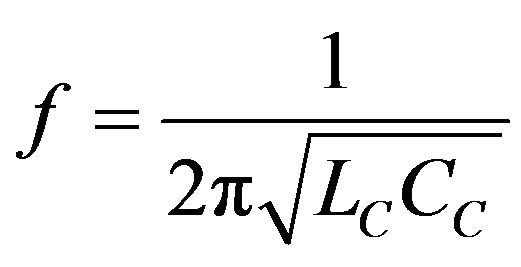 (1)
(1)
If the equivalence capacitance of the CSRR is increased, the resonant frequency shifts towards the low frequencies.
Figure 2 shows the optimized CSRR loaded by impedance [S] parameters simulated results. It shows a rejected frequency band around 2.5 GHz. In this case, we obtained a global size of the CSRR resonator around λg/20, showing a 50% reduction in size.
Figure 3 shows the bandstop filter based on optimized
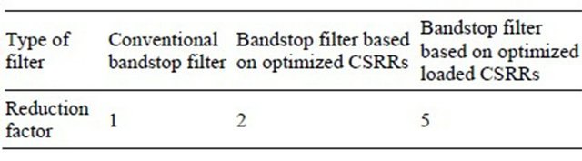
Table 1. Reduction factor of different bandstop filters.
CSRR loaded by impedance design.
The simulated results of this filter are shown in Figure 4. The latter shows a bandstop central frequency of 2.5 GHz with 23% fractional bandwidth. A deep rejection band (S21 = −25 dB) is obtained with low return loss.
Figure 6 shows the simulated group delay. It presents a very small variation in the operating frequency (<1 ns).
The electrical length of optimal filter is very small with only 0.08 λ0 thus, less than a fifth of the conventional filter electrical length (Table 1), while the bandstop performance is maintained.
4. Measured Results and Discussions
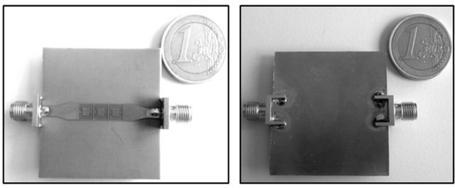
The filter based on the optimized CSRR without impedance was fabricated and shown in Figure 7. AGILENT TECHNOLOGIE-N5230A vector network analyzer was used to measure the response of the proposed filter and the results are shown in Figure 8.
A very good agreement is obtained between simulated and measured results. The measurement shows a bandstop central frequency of 5.75 GHz with 35% fractional bandwidth. A deep rejection band (S21 = −50 dB) is obtained in the vicinity of the designed frequency with low return losses.
5. Conclusions
In this paper, a very compact planar left-handed metama-
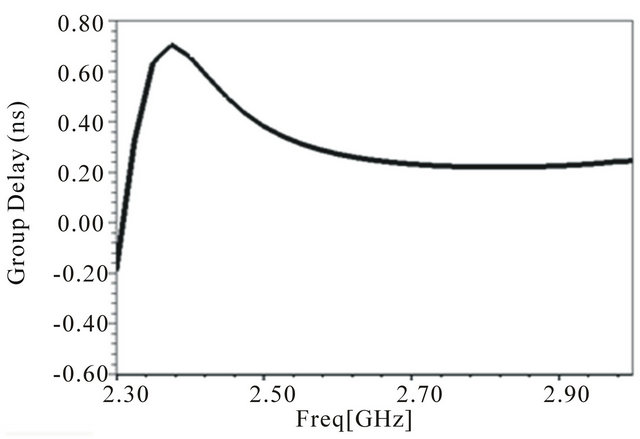
Figure 6. Simulated group delay for bandstop filter based on optimized loaded CSRRs.
 (a) (b)
Figure 7. Photograph of the fabricated device: (a) Top plane; (b) Bottom plane.
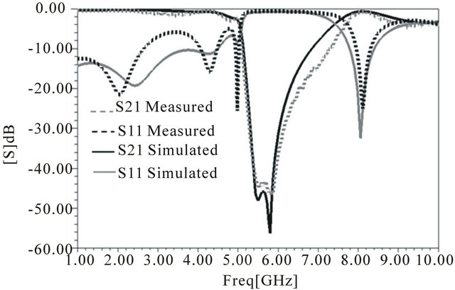
Figure 8. Simulated and Measured S parameters of the bandstop filter.
terial bandstop filter, which includes a 50 Ω line and an array of miniaturized CSRR has been demonstrated.
The combination of these two elements yields a resonator design with extremely small electrical outline dimensions. The electrical length of filter is very small with only 0.08 λ0, compared to conventional bandstop filter, a miniaturization of a factor 5 while the bandstop performance is maintained. The bandstop filters based on this concept can be very promising for the applications where miniaturization and compatibility with planar millimeter wave technology are the key issues.
REFERENCES
- J.-S. G. Hong and M. J. Lancaster, “Microstrip Filters for RF/Microwave Applications,” Wiley, New York, 2001. doi:10.1002/0471221619
- J. B. Pendry, A. J. Holden, D. J. Robbins and W. J. Stewart, “Magnetism from Conductors and Enhanced Nonlinear Phenomena,” IEEE Transactions on Microwave Theory and Techniques, Vol. 47, No. 11, 1999, pp. 2075- 2084. doi:10.1109/22.798002
- R. Marqués, F. Martin and M. Sorolla, “Metamaterials with Negative Parameters: Theory, Design and Microwave Applications,” John Wiley & Sons, Inc., Upper Saddle River, 2007.
- R. W. Ziolkowski and N. Engheta, “Metamaterial Special Issue Introduction,” IEEE Transaction on Antennas and Propagation, Vol. 51, No. 10, 2003, pp. 2546-2549. doi:10.1109/TAP.2003.818317
- F. Falcone, T. Lopetegi, J. D. Baena, R. Marqués, F. Martín and M. Sorolla, “Effective Negative Epsilon Stop-Band Microstrip Lines Based on Complementary Split Ring Resonators,” IEEE Microwave and Wireless Components Letters, Vol. 14, 2004, pp. 280-282. doi:10.1109/LMWC.2004.828029
- J. Garcia-Garcia, F. Martin, F. Falcone, J. Bonache, J. D. Baena, I. Gill, E. Amat, T. Lopetegi, M. A. G. Laso, J. A. M. Iturmendi, M. Sorolla and R. Marques, “Microwave Filters with Improved Stopband Based on Sub-Wavelength Resonators,” Microwave and Optical Technology Letters, Vol. 46, 2005, pp. 283-286.
- J. D. Baena, J. Bonache, F. Martin, R. Marqués Sillero, F. Falcone, T. Lopetegi, M. A. Glaso, J. Garcia-Garcia, I. Gil, M. F. Portillo and M. Sorolla, “Equivalent-Circuit Models for Split-Ring Resonators and Complementary Split-Ring Resonators Coupled to Planar Transmission Lines,” IEEE Transactions on Microwave Theory and Techniques, Vol. 53, No. 4, 2005, pp. 1451-1461. doi:10.1109/TMTT.2005.845211
- K. Aydin, I. Bulu, K. Guven, M. Kafesaki, C. M. Soukoulis and E. Ozbay, “Investigation of Magnetic Resonances for Different Split-Ring Resonator Parameters and Designs,” New Journal of Physics, Vol. 7, No. 1, 2005, p. 168. doi:10.1088/1367-2630/7/1/168
- R. Marques, F. Medina and R. Rafii-El-Idrissi, “Role of Bianisotropy in Negative Permeability and Left-Handed Metamaterials,” Physical Review B, Vol. 65, No. 14, 2002, Article ID: 144440. doi:10.1103/PhysRevB.65.144440
- H. Griguer, H. Lalj and M. Drissi, “SRR Miniaturization for Patch Antenna Stacked with Metamaterial Substrate,” Fourth International Congress on Advanced Electromagnetic Materials in Microwaves and Optics, Karlsruhe, 13-16 September 2010.
- F. Falcone, T. Lopetegi, J. D. Baena, R. Marques, F. Martin and M. Sorolla, “Effective Negative ɛ Stop-Band Microstrip Lines Based on Complementary Split-Ring Resonators,” IEEE Microwave and Wireless Components Letters, Vol. 14, 2004, pp. 280-282. doi:10.1109/LMWC.2004.828029