Green and Sustainable Chemistry
Vol.3 No.2(2013), Article ID:31981,21 pages DOI:10.4236/gsc.2013.32012
The Best Available Technology of Water/Wastewater Treatment and Seawater Desalination: Simulation of the Open Sky Seawater Distillation
Chemical Engineering Department, Saad Dahlab University of Blida, Blida, Algeria
Email: djamel_andalus@yahoo.fr
Copyright © 2013 Djamel Ghernaout. This is an open access article distributed under the Creative Commons Attribution License, which permits unrestricted use, distribution, and reproduction in any medium, provided the original work is properly cited.
Received March 16, 2013; revised April 18, 2013; accepted April 26, 2013
Keywords: Air Stripping (AS); Seawater; Water Treatment; Coagulation; Dissolved Air Flotation (DAF); Distillation
ABSTRACT
This review suggests the concept of the best available technology of water/wastewater treatment and seawater desalination which is in fact a simulation of the seawater distillation at the open sky: coagulation in salty water aerated basin/ coagulation using seawater as coagulant solution with distillation using stored solar energy followed by waterfall on a natural mountain. This natural, green, and technico-economical technology is composed of three steps: the first one is coagulation which may be achieved: 1) in salty water aerated basin (air stripping, AS; dissolved air flotation, DAF) where the raw water is “diluted” in seawater; or 2) in “conventional” coagulation using seawater as coagulant solution instead of alum/ferric salts. The first option seems to be more natural as it simulates river water dilution in seawater and the second one is more practical for “rapid” water consummation. For colloids and microorganisms’ removal, doublelayer compression and charge neutralisation, as main coagulation and disinfection mechanisms, would be involved in the first and second options, respectively. Aerated basin (AS/DAF) reproduces the natural aeration to simulate healthy natural water basin. Using stored solar energy, distillation as the best liquid-solid/liquid-liquid separation process provides the removal of dissolved pollutants. For well balanced calco-carbonic equilibrium, the last step of this green treatment is the waterfall on a natural mountain providing useful gases, dissolved oxygen and carbon dioxide, and mineral salts to the water.
1. Introduction
Although water is a renewable resource and we use little more than 10% of the total precipitation surplus for pub- lic water-supply, irrigation, and industrial processes, its availability is restricted through an uneven distribution, both in time and space. In this respect, there is no essential difference between ancient times and the present day; society has always experienced problems with water: too little, too much, too variable and too polluted. Over more than 6000 years mankind has tried to manage these water problems by intervening in its natural courses through redistribution, storage, and regulation, to accommodate their requirements for irrigation, drainage, flood protection, drinking water, sanitation, and power generation [1,2].
Health and aesthetics are the principal motivations for water treatment [3,4]. In the late 1800s and early 1900s, acute waterborne diseases, such as cholera and typhoid fever, spurred development and proliferation of filtration and chlorination plants. Subsequent identification in water supplies of additional disease agents (such as Legionella, Cryptosporidium, and Giardia) [5] and contaminants (such as cadmium and lead) resulted in more elaborate pretreatments to enhance filtration and disinfection [6]. Additionally, specialised processes such as granular activated carbon (GAC) adsorption and ion exchange were occasionally applied to water treatment [7] to control tasteand odour-causing compounds and to remove contaminants such as nitrates. In addition, water treatment (Table 1) can be used to protect and preserve the distribution system [8].
A variety of developments in the water quality field since the 1970s and an increasing understanding of health effects [4] have created an upheaval in the water treatment [7] field. With the identification in water of low levels of potentially harmful organic compounds, coliform-free and low-turbidity water is no longer suffi-

Table 1. Selection of unit processes for the removal of specific parameters [3].
cient. New information regarding inorganic contaminants, such as lead, is forcing suppliers to tighten control of water quality within distribution systems. Increasing pressures on watersheds have resulted in a heavier incoming load of microorganisms to many treatment plants. Although a similarly intense reevaluation of the aesthetic aspects of water quality has not occurred, aesthetic quality is important. Problems, such as excessive minerals, fixture staining, and colour, do affect consumer acceptance of the water supply. However, significant advances in the identification of tasteand odour-causing organisms and their metabolites have occurred within the last two decades [8].
Coagulation/flocculation (C/F) may be broadly described as chemical and physical processes that mix coagulating chemicals [9,10] and flocculation aids with water [11]. The overall purpose is to form particles large enough to be removed by the subsequent settling or filtration processes [12-14]. Particles in source water that can be removed by C/F, sedimentation [15], and filtration [16] include colloids, suspended material, bacteria, and other organisms [17]. The size of these particles may vary by several orders of magnitude. Some dissolved material can also be removed through the formation of particles in the C/F processes. The importance of dissolved material removal has become much more critical in recent years with increased regulatory emphasis on disinfection by-products (DBPs) and total organic carbon (TOC) removal [18,19].
This review is divided in two main sections. The first one concerns green, such as air stripping (AS), dissolved air flotation (DAF) and distillation and greenable processes such as coagulation using seawater salts as coagulant. The second section discusses briefly simulation of seawater distillation.
2. Green and Greenable Processes
2.1. Air Stripping (AS) and Aeration
Several different types of AS and aeration systems (Figure 1) are widely used for a variety of water treatment applications (Table 2) [7,20]. The most common types are diffused-air, surface aerator, spray, and packed-tower systems [21]. Water treatment applications for these systems include the absorption of reactive gases for water stabilisation and disinfection, precipitation of inorganic contaminants, and AS of volatile organic compounds (VOCs) and nuisance-causing dissolved gases [22,23]. The diffused-aeration (or bubble) systems are primarily used for the absorption of reactive gases, such as oxygen (O2), ozone (O3), and chlorine (Cl2). Oxygen is frequently used for the oxidation/precipitation of iron and manganese. Ozone is used for disinfection, colour removal, and oxidation of TOC. Chlorine is primarily used for disinfection and sometimes as a pre-oxidant for the oxidation of iron and manganese or for other purposes. Diffused-aeration systems have also been used for the stripping [23] of odour-causing compounds and VOCs. Surface-aeration systems are primarily used for VOCs removal. The packed-tower and spray nozzle systems are primarily used for the removal of NH3, CO2, H2S, and VOCs. The packed-tower systems include counter-cur-
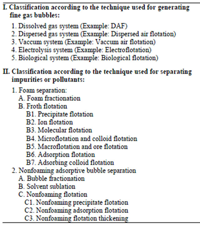
Table 2. Classification of adsorptive bubble separation processes [21].

Figure 1. Waterfalls in the “virgin” Earth providing dissolved gas (O2(g), CO2(g)) and salts (Ca2+, Mg2+) to water for well balanced calco-carbonic equilibrium.
rent flow, co-current flow, and cross-flow configurations. Spray nozzle systems can include tower and fountaintype configurations [24].
Hand et al. [24] discussed a fundamental understanding of the theory of gas transfer, followed by a description of the various unit operations, development of the design equations, and example design calculations. As unit operations, Hand et al. [24] presented packed towers, diffused or bubble aeration, surface aeration, spray aerators. In this review, we give here some generalities about the three last unit operations which are practically more convenient to actual (conventional) water treatment plants [7] since they can be added or introduced in sedimentation basin [15]. More theoretical details and practical examples may be found in this good reference [24].
2.1.1. Diffused or Bubble Aeration
The diffused or bubble aeration process consists of contacting gas bubbles with water for the purposes of transferring gas to the water (e.g., O3, CO2, O2) or removing VOCs from the water by stripping [23]. The process can be carried out in a clear well or in special rectangular concrete tanks typically 2.74 to 4.57 m (9 to 15 ft) in depth [24]. Figure 2 displays different types of diffused aeration systems. The most commonly used diffuser system consists of a matrix of perforated tubes (or membranes) or porous plates arranged near the bottom of the tank to provide maximum gas-to-water contact. Various types of diffusers and diffuser system layouts are presented in the Environmental Protection Agency’s technology transfer design manual on fine-pore aeration systems (loc.cit.,EPA/625/1-89/023) [24]. Jet aerator devices are also used to provide good air-to-water contact. These aerators consist of jets that discharge fine gas bubbles and provide enhanced mixing for increased absorption efficiency [24].
2.1.2. Surface Aeration
Surface aeration has been primarily used for oxygen absorption and the stripping of gases and volatile contaminants [23] when the required removals are less than about 90 percent. Surface aeration devices consist of the brush type or turbine type, as shown in Figure 3. The brush-

Figure 2. Schematic of various bubble aeration systems [24].
type aerator consists of several brushes attached to a rotary drum, which is half-submerged in water in the centre of the tank. As the drum rotates, it disperses the water into the surrounding air providing reasonable contact between the air and water for mass transfer to take place. The turbine-type aerator consists of a submerged propeller system located in the centre of the tank and surrounded by draft tubs. As the submerged propeller rotates it draws water from outside the draft tubs through the inner section and into the air creating contact between the air and water. These types of systems have been extensively used in the aeration of wastewater [25] and their design and operation have been well documented [24].
2.1.3. Spray Aerators
Spray aerators have been used in water treatment for many years to oxygenate groundwater [26] for the purpose of iron and manganese removal and the AS of gases (i.e., CO2, H2S) and VOCs [23]. Effective iron oxidation

Figure 3. Schematic of various surface aeration devices [24].
by aeration usually requires at least 1 h of retention time after aeration. Manganese oxidation by aeration is very slow and not practical for waters with pH values below 9.5. Manganese removal usually requires a stronger oxidant. CO2 and H2S removals have ranged from 50 to 90 percent depending upon the pH of the water. VOCs removals have been as high as 90 percent depending upon the Henry’s law constant [22,24,27]. Figure 4 displays a schematic of a single fountain-type spray aerator.
Spray aerator systems consist of a series of fixed nozzles on a pipe grid. The grids can be placed in towers, commonly known as spray towers (or fountains), that spray onto the surface [28] of raw water reservoirs. Pressurised nozzles disperse fine water droplets into the surrounding air, creating a large air-water surface for mass transfer. Two types of pressurised spray nozzles, hollowand full-cone, are commonly used in water treatment [7]. Full-cone nozzles deliver a uniform spray pattern of droplets. The hollow-cone nozzle delivers a circular spray pattern with most of the droplets concentrated at the circumference. The hollow-cone nozzle is generally preferred over the full-cone type because it provides smaller droplets for better mass transfer even though it has a larger pressure drop requirement. Hollow-cone spray droplets are around 5 mm and are prone to plugging. It is recommended that in-line strainers be installed in the spray nozzle manifold to prevent plugging [24].
The fountain-type spray aerators have been more widely used in water treatment because they can be easily adapted to existing water treatment systems. The design approach and application of the fountain type is presented in [24].
2.2. Coagulation
Coagulation [18,29,30] is a process for increasing the
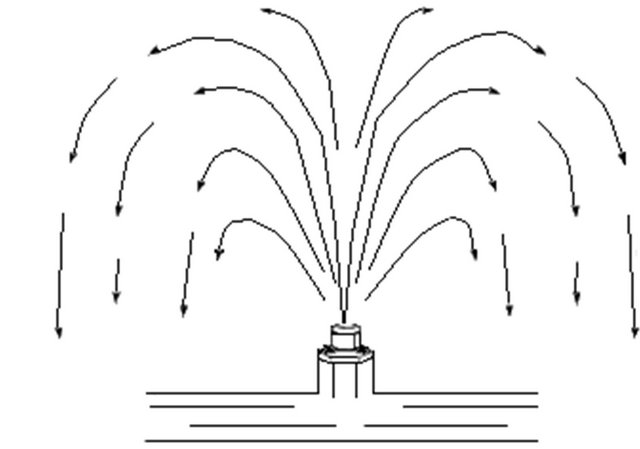
Figure 4. Schematic of a single-fountain spray aerator [24].
tendency of small particles in an aqueous suspension to attach to one another and to attach to surfaces such as the grains in a filter bed (Table 3). It is also used to effect the removal of certain soluble materials by adsorption or precipitation [31]. The coagulation process typically includes promoting the interaction of particles to form larger aggregates [18]. It is an essential component of conventional water treatment systems [7] in which the processes of coagulation, sedimentation [15], filtration, and disinfection are combined to clarify the water and remove and inactivate microbiological contaminants such as viruses, bacteria, and the cysts and oocysts of pathogenic protozoa [32]. Although the removal of microbiological contaminants continues to be an important reason for using coagulation, a newer objective, the removal of natural organic material (NOM) to reduce the formation of DBPs, is growing in importance [19,33-35].
Aluminium and ferric iron salts have long been used to remove colour caused by NOM [36]. These organic substances are present in all surface waters and in many groundwaters [26]. They can be leached from soil, diffused from wetland sediments [37], and released by plankton and bacteria. NOM adsorbs on natural particles and acts as a particle-stabilising agent in surface water [35]. It may be associated with toxic metals and synthetic organic chemicals (SOCs) [38]. NOM includes precursor compounds that form health-related by-products [4] when chlorine and other chemical disinfectants are used for disinfection and oxidation. For these reasons, considerable attention is being directed at the removal of NOM by coagulation in water treatment, even when colour removal is not the principle objective [7]. A treatment technique requirement in the U.S. Environmental Protection Agency’s (USEPA’s) Stage 1 Disinfection By-Products Rule requires NOM removal in conventional treatment systems by the practice of enhanced coagulation [11, 18,33,39].
Coagulation has been an important component of highrate filtration plants in the United States since the 1880s. Alum and iron (III) salts have been employed as coagu-
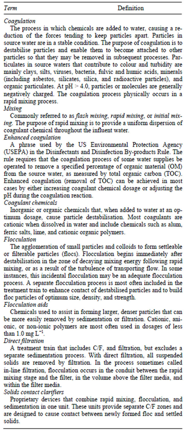
Table 3. Terms used in coagulation literature [18].
lant chemicals [9] since the beginning, with alum having the most widespread use. In the 1930s, Baylis perfected activated silica as a “coagulant aid”. This material, formed on site, is an anionic polymer or a small, negatively charged colloid [40]. Synthetic organic polymers [41] were introduced in the 1960s, with cationic polymers having the greatest use. Natural starches were employed before the synthetic compounds. Polymers have helped change pretreatment and filtration practice, including the use of multimedia filters and filters with deep, uniform grain-size media, high-rate filtration, direct filtration (rapid mixing, flocculation, and filtration, but no sedimentation), and in-line filtration (rapid mixing and filtration only) [23,33].
Coagulants are also being used to enhance the performance of membrane microfiltration systems [42] and in pretreatment that prolongs the bed life of GAC contactors [43]. The development of new chemicals, advances in floc [44] removal process and filter design, and particle removal performance standards and goals have stimulated substantial diversity in the design and operation of the coagulation process, and change can be expected to continue into the future [45]. In evaluating high-rate filtration plants that were producing high-quality filtered water, Cleasby et al. [46] concluded, “Chemical pretreatment prior to filtration is more critical to success than the physical facilities at the plant.” Their report recommends that plant staff use a well-defined coagulant chemical control strategy that considers variable rawwater quality. There is no question that highrate (rapid sand) filtration plants are coagulant-based systems that work only as well as the coagulants that are used [32,33].
2.2.1. Properties of Colloidal Systems
Colloids are very small particles that have extremely large surface area [47]. Colloidal particles [48] are larger than atoms and ions but are small enough that they are usually not visible to the naked eye. They range in size from 0.001 to 10 μm resulting in a very small ratio of mass to surface area. The consequence of this smallness in size and mass and largeness in surface area is that in colloidal suspensions [49]: a) gravitational effects are negligible, and b) surface phenomena predominate.
Because of their tremendous surface, colloidal particles have the tendency to adsorb various ions from the surrounding medium that impart to the colloids an electrostatic charge relative to the bulk of surrounding water [40,50]. The developed electrostatic repulsive forces prevent the colloids from coming together and, consequently, contribute to their dispersion and stability.
1) Electrokinetic Properties The electrokinetic properties of colloids can be attributed to the following three processes [33,49]:
a) Ionisation of groups within the surface of particles.
b) Adsorption of ions from water surrounding the particles.
c) Ionic deficit or replacement within the structure of particles.
Organic substances and bacteria acquire their surface charges [40] as a result of the ionisation of the amino and carboxyl groups as shown below:
R-NH3+ → R-NH2 + H+ (1)
R-COOH → R-COO- + H+ (2)
The resulting charge on the surface of such particles is a function of the pH [40]. At high pH values or low hydrogen ion concentrations, the above reactions shift to the right and the colloid is negatively charged. At a low pH, the reactions shift to the left, the carboxyl group is not ionised, and the particle is positively charged due to the ionised amino group. When the pH is at the isoelectric point (IEP), the particle is neutral, i.e., neither negatively nor positively charged. Proteinaceous material, containing various combinations of both amino and carboxyl groups, are usually negatively charged at pH values above 4 [47].
Oil droplets adsorb negative ions, preferably hydroxides (OH−), from solution and, consequently, they develop a negative charge [40,50]. Some other neutral particles adsorb selected ions from their surrounding medium such as calcium (Ca2+) or phosphate  ions rendering them either positively or negatively charged, respectively.
Clays and other colloidal minerals may acquire a charge as a result of a deficit or imperfection in their internal structure [40]. This is known as isomorphic replacement [47]. Clays consist of a lattice formed of cross-linked layers of silica and alumina. In some clays there are fewer metallic atoms than nonmetallic ones within the mineral lattice producing a negative charge [40]. In others, higher valency cations may be replaced by lower valency cations during the formation of the mineral lattice that renders the clay particles negatively charged [40]. Examples of such imperfection include: a) the substitution of an aluminium ion (Al3+) by either Mg2+ or Fe2+; and b) the replacement of Si4+ cation by Al3+. According to Letterman et al. [33], the type and strength of the charge resulting from this imperfection in the clay structure are independent of the surrounding water properties and pH. This is in contrast to the first two processes discussed above, in which both pH and ionic makeup of the surrounding solution play a big role in determining the sign and magnitude of the acquired charge on colloidal particles [47].
2) Hydration Water molecules may also be sorbed on the surface of colloids, in addition to or in place of, other molecules or ions. The extent of this hydration depends on the affinity of particles for water. Colloidal particles that have watersoluble groups on their surface such as hydroxyl, carboxyl, amino, and sulfonic exhibit high affinity for hydration and cause a water film to surround the particles. Such colloids are classified as hydrophilic (water loving) particles. On the other hand, colloids that do not show affinity for water and do not have bound water films are classified as hydrophobic (water hating) [47].
3) Brownian Movement Colloids exhibit a continuous random movement caused by bombardment by the water molecules in the dispersion medium [51]. This action, called Brownian movement, imparts kinetic energy to the particles that tends to cause an increase in the frequency of collisions [44], thus promoting coagulation. Elevated temperature increases molecular velocity resulting in more kinetic energy and more intense Brownian movement [44,47].
4) Tyndall Effect Because colloidal particles have an index of refraction different from water, light passing through the dispersion medium and hitting the particles will be reflected. The turbid appearance due to this interference with the passage of light is termed the Tyndall effect. However, it should be noted that this might not always be the case. Water-loving, hydrophilic, colloids may produce just a diffuse Tyndall cone or none at all. The reason for this behaviour can be attributed to the bound water layer surrounding colloids. These particles will have an index of refraction not very different from that of the surrounding water. Hence, the dispersed phase and the dispersion medium behave in a similar fashion toward the passage of light [47].
2.2.2. Destabilisation of Colloids
Destabilisation [44] of colloidal particles is accomplished by coagulation through the addition of hydrolysing electrolytes such as metal salts and/or synthetic organic polymers [52]. Upon being added to the water, the action of the metal salt is complex [33,47]. It undergoes dissolution, the formation of complex highly charged hydrolysed metal coagulants (hydroxyoxides of metals), interparticle bridging [11,53], and the enmeshment of particles into flocs [44]. Polymers work either on the basis of particle destabilisation or bridging between the particles [53].
The destabilisation process is achieved by the following four mechanisms of coagulation [11,53-55]:
a) Double-layer compression (DLC).
b) Adsorption and charge neutralisation (CN).
c) Entrapment of particles in precipitate (sweep coagulation, SC).
d) Adsorption and bridging between particles.
1) Double-Layer Compression When high concentrations of simple electrolytes are introduced into a stabilised colloidal dispersion, the added counter-ions penetrate into the diffuse double layer [51] surrounding the particles rendering it denser and hence thinner and smaller in volume. The addition of counterions with higher charges [40], such as divalent and trivalent ions, will result in even steeper electrostatic potential gradients and more rapid decrease in charge with distance from the surface of the particles. The net repulsive energy (see Figure 5) would become smaller or even would be completely eliminated, allowing the particles to approach each other and agglomerate [47].
A mathematical model that describes this coagulation mechanism is explained in detail in [56]. The prediction of this model is in agreement with what is known as the Schultze-Hardly rule. This rule states that the coagulation of colloidal particles is achieved by ions of added electrolytes, which carry opposite charge to that of the colloids, and that the destabilisation capability [44] of the ions rises sharply with ion charge. Table 4 [49] illustrates the relative effectiveness of various electrolytes in the coagulation of negatively and positively charged colloids. For example, the relative power of Al3+, Mg2+, and Na+ for the coagulation of negative colloids is shown to vary in the ratio of 1000:30:1. A similar ratio is observed for the relative capability of ,
,  , and Cl− for the coagulation of positively charged colloids.
2) Adsorption and Charge Neutralisation (CN)
For all practical purposes, the ability of a chemical substance to destabilise and coagulate colloidal particles is the result of a combination of several mechanisms. Longchained organic amines are often mentioned as being typical coagulants that function by adsorption and electrostatic neutralisation [33,47,49]. The positively charged organic amine molecules (R- ) are easily and quickly attached to negatively charged colloidal particles. The charge on the particles gets neutralised and the electrostatic repulsion is decreased or eliminated resulting in the destabilisation of the colloids and hence their agglomeration [40]. The organic amines are hydrophobic because there is a lack of interaction between the CH2 groups in their R-chain and the surrounding water. As a result, these positively charged ions are driven out of the water and get adsorbed on the particulate interface. An overdose of R-
 counter-ions, however, can lead to charge reversal from negative to positive and the restabilisation of the dispersion system.
When coagulants such as metal salts are added to water, they dissociate yielding metallic ions, which undergo hydrolysis and form positively charged metallic hydroxyoxide complexes [47]. The commonly used coagulants, trivalent salts of aluminium and iron, produce numerous species because the hydrolysis products themselves tend to polymerise to give polynuclear metallic hydroxides [47]. Examples of aluminium salt polymers
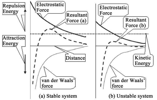
Figure 5. Effect of interparticle forces on the stability of a colloidal system [47].
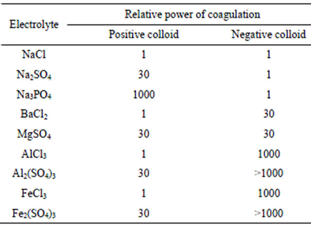
Table 4. Relative coagulation power of electrolytes [47].
are 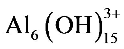 and
and  and of iron salt polymers are
  and
and . When such polyvalent complexes possessing high positive charges get adsorbed on to the surface of the negatively charged colloids, the result is again a neutralisation of the charges, decrease in the repulsion energy, and destabilisation of the colloids. In a similar fashion to what occurs with the organic amines, an overdose of metallic salts could reverse the colloidal charge and restabilise the particles.
3) Entrapment of Particles in Precipitate When the coagulants alum [Al2(SO4)3] or ferric chloride (FeCl3) are added in high enough concentration, they will react with hydroxides (OH−) to form metal hydroxide precipitates, Al(OH)3(s) or Fe(OH)3(s) respectively. The colloidal particles get entrapped in the precipitates either during the precipitate formation or just after. This type of coagulation by enmeshment of colloids in precipitates is commonly called sweep coagulation (SC) [33,47,55].
There are three elements that influence this coagulation mechanism [47]:
a) Oversaturation: The rate of precipitation is a function of oversaturation with the metal hydroxide. To obtain fast precipitation and efficient SC, high concentrations of Al(OH)3(s) or Fe(OH)3(s) are required.
b) Presence of anions: The rate of precipitation is improved by the presence of various anions in water. The most effective anions in this respect are the sulphate ions.
c) Concentration of colloids: The rate of precipitation is also improved with higher concentration of colloidal particles. The reason for this is that the colloids themselves could act as nuclei for the formation of precipitates. In this case, it can be concluded that lower rather than higher coagulant dosage will be required to coagulate water having higher colloidal particle concentration.
4) Adsorption and Bridging between Particles Polymers destabilise colloidal particles through the formation of bridges that extend between them [47]. The polymers have reactive groups that bind to specific sites on the surface of the colloidal particles. When a group on a polymer molecule attaches to a colloid, the remainder of the long-chain molecule extends away into the water. Once the extended portion of the polymer gets attached to another colloidal particle, the two particles become tied together or bridged by the polymer. If no other particle is available or if there is an overdose of polymer, the free extended portions of the polymer molecule would wrap around the same original particle, which could effectively bring about the restabilisation of the colloid. Restabilisation can also occur due to aggressive mixing or extended agitation, which may break the interparticle bridging and allow the folding back of the freed polymer portions around the same original particle (see Figure 6).
2.2.3. Phenomena of Coagulation
For Eckenfelder [29], coagulation results from two basic phenomena:
• Perikinetic (or electrokinetic) coagulation, in which the zeta potential (ZP) is reduced by ions or colloids of opposite charge to a level below the van der Waals attractive forces [57-59], and
• Orthokinetic coagulation—fluid motion [44,60]—in which the micelles aggregate and form clumps that agglomerate the colloidal particles.
The addition of high-valence cations depresses the particle charge and the effective distance of the double layer, thereby reducing the ZP [57]. As the coagulant dissolves, the cations serve to neutralise the negative charge on the colloids. This occurs before visible floc formation [44], and rapid mixing which “coats” the colloid is effective in this phase. Microflocs are then formed which retain a positive charge in the acid range because of the adsorption of H+. These microflocs also serve to neutralise and coat the colloidal particle. Flocculation agglomerates the colloids with a hydrous oxide floc. In this phase, surface adsorption is also active. Colloids not initially adsorbed are removed by enmeshment in the floc [23,29].
A desired sequence of operation for effective coagulation was outlined [29]. If necessary, alkalinity should first be added (bicarbonate has the advantage of providing alkalinity without raising the pH). Alum or ferric salts are added next; they coat the colloid with Al3+ or Fe3+ and positively charged microflocs. Coagulant aids such as activated silica and/or polyelectrolyte [41] for floc build-up [45,61] and ZP control, are added last. After addition of alkali and coagulant, a rapid mixing of 1 to 3 min is recommended, followed by flocculation [23], with addition of coagulant aid, for 20 to 30 min. Destabilisation can also be accomplished by the addition of cationic polymers, which can bring the system to the IEP without a change in pH. Although polymers [3,62] are 10 to 15 times as effective as alum as a coagulant they are considerably more expensive (Tables 5 and 6). The mechanism of the coagulation process is shown in Figure 7.
However, DLC and CN may be classified as electrokinetic coagulation and SC and bridging between particles [63] may be attributed to orthokinetic coagulation [60] (Figure 8).
2.2.4. Polymer Toxicity
The normally used anionic and nonionic polymers are of low toxicity generally, but cationic types are more toxic, especially to aquatic organisms. Concerns about contaminants have led Japan and Switzerland not to permit the use of polyelectrolytes in drinking water treatment, whilst Germany and France have set stringent limits. The monomers are more toxic than the polymers [64]. Limits on the level of monomer are strictly controlled, especially with acrylamide products, where as a general rule the maximum allowable content of free acrylamide is 0.025%, and the residue in drinking water is limited to 0.5 μg∙L−1 [41].
2.3. Distillation
Distillation is the most commonly used method for the separation of homogeneous fluid mixtures [27,65]. Separation exploits differences in boiling point, or volatility, between the components in the mixture [66,67]. Repeated vaporisation and condensation of the mixture allows virtually complete separation of most homogeneous fluid mixtures [68]. The vaporisation requires the input of energy [69,70]. This is the principal disadvantage of distillation: its high energy usage [71,72]. However, distillation has three principle advantages over alternative methods for the separation of homogeneous fluid mixtures [73]:
1) The ability to handle a wide range of feed flow rates. Many of the alternative processes for the separation of
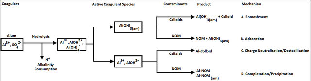

Figure 6. Conceptual view of coagulation reactions [54].
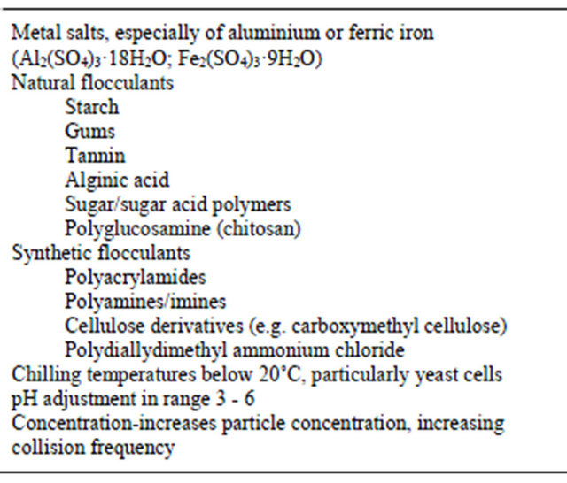
Table 5. Coagulants and flocculants, adjustment of conditions or addition of specific chemicals achieves required increase in particle size [62].
fluid mixtures can only handle low flow rates, whereas distillation can be designed for the separation of extremely high or extremely low flow rates.
2) The ability to separate feeds with a wide range of feed concentrations. Many of the alternatives to distillation can only separate feeds that are already relatively pure.
3) The ability to produce high product purity. Many of the alternatives to distillation only carry out a partial separation and cannot produce pure products.
It is no accident that distillation is the most common method for the separation of homogeneous mixtures [74]. It is a versatile, robust and well-understood technique [73].
2.3.1. Process Description
Distillation is a physical process for separating a liquid mixture into its constituents [75]. When such a mixture is partially vaporised, the vapour normally has a composition different from that of the residual liquid [15]. Implied in the method is the condensation of the vapour to form a product liquid, called the distillate [68]. The residual liquid product is often called the bottoms.
Distillation in crude form was practiced over 2000 years ago, usually for the concentration of alcoholic spirits. The first formalised documentation of distillation appears to be the treatise by Brunschwig in 1500 [75]. Distillation has since emerged as the key method for separating liquid mixtures in chemical processing and related industries because of its versatility, simplicity, economy, and many years of experience.
Early distillations were of the batch, takeover type, sometimes called simple distillation or differential distillation. A charge of liquid mixture is vaporised from a still, or stillpot, by heat addition, and the product vapour is condensed into one or more fractions [15]. Thus the term fractional distillation, or fractionation, has become associated with any distillation operation designed to obtain defined or specified constituent fractions [75].
Most distillations today are of the multistage rectification type, operated continuously or in the batch mode [75]. They are characterised by vertical vessels (distillation columns) with internal contacting devices (usually trays or packings) that provide intimate contacting of
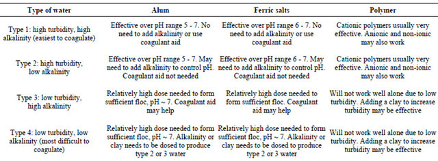
Table 6. Properties of variety of coagulants [3].
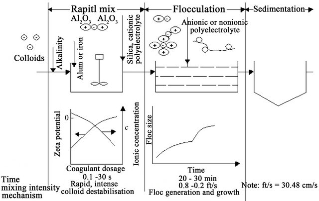
Figure 7. Phenomena of coagulation [29].
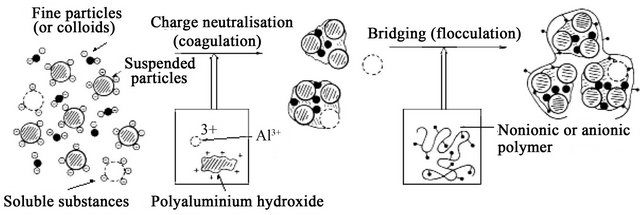
Figure 8. Schematic model of C/F process [63].
vapour and liquid. When operated continuously (the usual preferred mode), the towers are normally fed with a liquid mixture near the centre of the column, providing a stripping zone below the feed point and a rectifying zone (or “enriching zone”) above the feed point. A diagram of a typical distillation column is shown in Figure 9. Heat is added at the base of the column by vapour from a reboiler and is removed at the top of the column in a condenser to provide the distillate product [15]. Part of the distillate is returned to the column as reflux liquid.
2.4. Dissolved Air Flotation (DAF)
DAF is a solid-liquid separation process for the removal of fine suspended material from an aqueous suspension [76,77]. The basic principle underlying DAF is Henry’s law, which gives the solubility of air in water. According to Henry’s law, the solubility of air in water is directly proportional to its partial pressure. A supersaturated solution of water is produced using high pressure in a saturator. The bubbles are generated by the pressure release
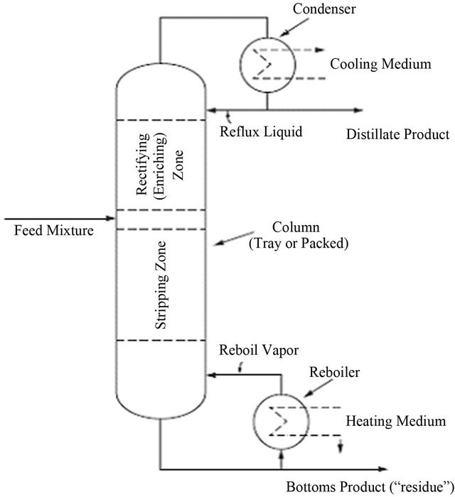
Figure 9. Distillation system operated in a continuous mode [75].
of this water stream [12]. These bubbles attach to suspended material present in the aqueous stream, causing them to float to the surface, where they are collected as floc [44,76].
DAF can be carried out by vacuum or pressurised methods [78]. In the vacuum flotation method [23] the water to be treated is saturated with air at atmospheric pressure. The bubbles are produced by applying a vacuum to the flotation tank, releasing the air as fine bubbles [15,79]. The vacuum flotation process has several disadvantages. These are 1) the amount of air available for flotation is limited by the vacuum achievable, 2) it is a batch process, and 3) it requires special equipment to produce and to maintain high vacuum. These disadvantages limit the application of vacuum flotation and it is only used in wastewater [80] sludge thickening [76].
The pressure flotation process is the most widely used DAF technique [78]. High pressure water is saturated with air. This pressurised water forms small bubbles when injected into water at atmospheric pressure. Three types of pressurisation processes can be used in DAF: full flow, partial flow and recycle flow pressurisation. The entire inlet stream is pressurised in full flow pressure DAF. It is commonly used when the wastewater [80] contains large amounts of suspended solids and the pressurisation process does not affect the treatment efficiency of the system. Partial flow pressurisation is used where the wastewater [81,82] contains moderate to low concentrations of suspended solids. In the recycle flow pressurisation system, 10% - 25% of the clarified effluent is recycled through a pressure vessel to the flotation tank. The flocculation process [23,83] in not disturbed in the recycle flow system because of intense mixing and pressurisation as clear water is pumped. A recycle flow system is cost-efficient because it pressurises only part of the water, thus requiring less compressor power. Recycle flow pressure flotation is the best-suited system for most DAF applications [76].
DAF is an effective alternative to sedimentation [15]. The advantages and disadvantage of DAF relative to sedimentation are presented in Table 7 [76].
2.4.1. Process Description
A schematic diagram of a DAF process for wastewater treatment is shown in Figure 10. Its essential elements are a flocculation tank, a flotation tank, an air compressor, an air saturator, a recycling pump and a hydrosweep system. The wastewater [80,84,85] is pumped to the flocculation tank after being treated with coagulant/flocculent agents such as aluminium sulphate [23,83]. A portion of the clarified effluent is recycled for pressurisation. Compressed air is introduced into the discharge stream of the recycle pump, and the water is saturated with air at high pressure. The pressurised water stream is introduced to the flotation tank through nozzles, where fine bubbles (20 - 100 μm) in diameter are formed. The bubbles attach themselves to suspended solid particles, causing the agglomerates to float to the surface of the tank [78]. The float can be mechanically skimmed from the surface, and the clarified water is taken from the bottom of the flotation tank [76].
2.4.2. Principles of Dissolved Air Flotation (DAF)
DAF facilities are composed of the following four principal steps:
1) C/F prior to flotation.
2) Bubble generation.
3) Bubble-floc collision and attachment in the mixing zone [78].
4) Rising of the bubble-floc aggregates in a flotation tank [76].
3. Simulation of Seawater Distillation
This paper presents the concept of the best available
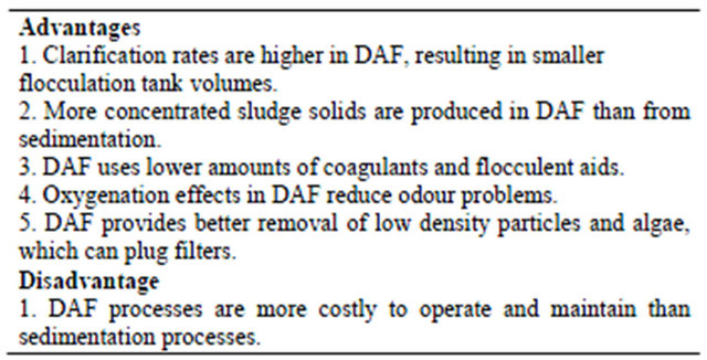
Table 7. The advantages and disadvantage of DAF relative to sedimentation [76].
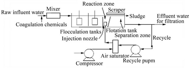
Figure 10. Schematic diagram of the DAF process for water treatment [76].
technology (BAT) of water/wastewater treatment and desalination which is in fact a simulation of seawater distillation at open sky: rapid mixing (coagulation) in salty water aerated basin (AS/DAF)/rapid mixing (coagulation) using seawater as coagulant solution with heating (distillation) using stored solar energy followed by waterfall (natural AS) on natural (artificial) mountain. This natural (i.e. non-“artificial” chemical) technology is composed of three steps: the first one is coagulation which may be achieved: 1) in salty water aerated basin (AS/DAF) where raw water is “diluted” in seawater; or 2) in “conventional” coagulation using seawater as coagulant solution instead of alum/ferric chloride. The first option is more natural as it simulates river water dilution in seawater and the second is more practical for “rapid” water consummation. For colloidal matters removal, double-layer compression (DLC) and charge neutralisation (CN), as main coagulation (and disinfection) mechanisms, would be involved in the first and second options, respectively. Aerated basin (AS/DAF) reproduces the natural aeration to simulate healthy natural water basin. Using stored solar energy, distillation as the best liquidsolid/liquid-liquid separation process provides the removal of dissolved pollutants. The last step is the waterfall (natural AS) on natural (or made of rocks) mountain providing dissolved gas (O2(g), CO2(g)) and salts (Ca2+, Mg2+) to water for well balanced calco-carbonic equilibrium. This natural “three-therapy”, needing technicoeconomical studies for its large application, will be helped by direct substitution of the actual convention water treatment plants as it uses rapid mixing basin for coagulation step, the flocculation, sedimentation, and filtration basins may be used for their initial aims, distillation basin may be added before the waterfall (natural AS) on natural (artificial) mountain.
Distillation [27,68] is a unit operation in which the components of a liquid solution are separated by vaporisation and condensation. Specially designed reactors are used to vaporise the water undergoing treatment, leaving behind waste brine that must be disposed of.
In desalination industry [86], distillation methods comprise the following modifications:
1) Multiple-effect evaporation (ME).
2) Multi-stage-flash evaporation (MSF).
3) Vapour-compression methods (VC).
4) Solar distillation method (SD).
Distillation (Figure 11) is the most developed process of removing water from a saline solution. It is applied up to very large capacities with various types of evaporators and accounts for about 59.4% of the total world plant capacity. The latent heat of changing phase is an important factor in the overall process economics, but the degree of salinity of the raw water is of no importance. MSF distillation and ME evaporation are reducing considerably the economic effect of the latent heat of vaporisation [86].
3.1. Decomposition of Organic Matter (OM) in Seawater
Organic matter (OM) is represented on this planet by living (autotrophic and heterotrophic) organisms and their excretory products and after-death remains, but may also be “inert” or non-living (refractory). The latter is found in large accumulations (fuel deposits, soils), as well as in the dispersed state in most mountain rocks and ocean waters [87]. Many authors believe that “inert” OM is of biogenic origin and that in reservoirs it dominates “living” OM [88].
In seas and oceans [87] refractory OM is mainly of autochthonous origin, the intake from land being comparatively small. Its primary source is phytoplankton. Heterotrophic organisms use phytoplankton as food for growth and for replacing expended energy. Excretory products of organisms and their remains are consumed by bacteria. As a result, the primary produced OM undergoes various conversions caused mainly by the activity of enzymes [89]. But despite all transformations, the OM of phytoplankton is not completely converted into
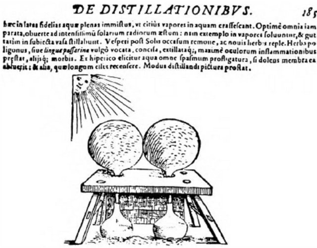
Figure 11. The first historically known solar distillation equipment, according to Giovanni Batista De La Porta; the sun evaporates the water inside the glass vessels and distilled water is collected beneath the vessels [86].
the mineral components which initially served as nutrients. Experiments testify that the remaining part is not large, and the rate of its biochemical conversion is slow. Krogh [90] considered the dissolved OM of oceans to be the result of the total OM turnover. One way of studying the processes of OM decomposition is to perform a series of long-term experiments on decomposition of OM from dead algae [88,90].
3.1.1. Water Humus
The analysis of the results of the experiments on decomposition of OM in dead plankton presents a view of the time-related changes of particulate and dissolved organic C, N and P, and some components of OM. The processes occurring are responsible not only for oxidation of the initial OM, but also in soils [91] for the polymerisation (condensation of the more biochemically resistant dissolved and particulate fractions of OM) [88].
Synchronically, new forms of OM are synthesised by bacteria. The combined processes lead to the formation of the refractory organic substance-water humus-in particulate and dissolved state. This surely occurred initially in the Precambrian period with blue-green algae and bacteria in water reservoirs under anoxic conditions [92-94]. As shown by experiments, the degree of decomposition of the OM of dead hydrobionts under such conditions was less. That is why more organic residues settled on the bottom of the reservoir. Naturally this influenced the further transformation of OM in sediments [37] and the accumulation of oil precursors [88,90].
Berzelius [94] appears to have pioneered a serious study of OM in natural waters. He discovered the dissolved organic compounds with acidic properties in the mineral spring Porla (Sweden). These compounds were called crenic and apocrenic acids. Berzelius [94] assumed that their salts were washed out from soil humus “intact”. Oden [95] found the common term for these acids— fulvic acids (fulvus = yellow). Aschan [96] attributed them to the water humus group, being typical for peat, river and lake waters [88].
Thus, fulvic acids may originate from continental plants, and when carried by rivers and streams to the reservoirs, seas and oceans [87], they constitute the major part of the allochthonous water humus. Kalle (1966) [97] suggested they were only partly responsible for the “yellow substance” (Gelbstoffe) present in oceanic waters, the concentration of which in the water decreases with the increase of salinity. He considered that a part of the “yellow substance” was of autochthonous origin. It seems probable, that its existence in water is due to transformed products of excretion of dissolved and thinly dispersed OM which was discovered in littoral algae during studies conducted by some researchers [88]. According to Birge and Juday [98], the refractory OM appears in the process of decomposition of dead plankton in lakes. This is the water humus of autochthonous origin. Krogh [90] considered that in the deep waters of the ocean OM consists partly of “humus”, which is resistant even for bacteria. Waksman [99], studying the question of the formation of OM in reservoirs, distinguished three types of humus: river, lake and sea humus. Besides this natural water humus, there may enter and be formed a humus from sewage of domestic origin. It was Odum [100] who considered humic substance (humus), the most stable product of OM decomposition in nature, to be a necessary component of the ecosystem.
Thus, it appears that water humus is the indispensable resistant product resulting from transformation, decomposition and synthesis of OM of excretions and dead remains of plankton in the ocean [87]: its final structure is largely determined by the activity of microorganisms [88].
Table 8 [101-103] summarises data to allow an approximate budget of water humus in the ocean. It is assumed that the annual decrease as a result of oxidation, aggregation and adsorption on the surface of particles with their subsequent sedimentation, equals its input [88].
The main differences observed between the calculated elements in a budget are typical in the amounts of organic C from the annual input reaching the ocean bottom. The bottom deposits also contain the aggregation products of dissolved OM. Scientists [88] estimated it to be n × 1015 g∙C, where n < 5. River inputs are relatively low in comparison to the total organic production. The input of OM from atmospheric precipitation has been neglected, since a similar amount of OM seems to be carried out from the ocean surface by strong winds. Duce and Duursma [104] draw special attention to the works devoted to studies of the release of marine OM into the atmosphere and the input of river OM into the oceans. Recent data obtained give some estimation of OM content in the atmosphere. Researchers [88] investigated the surface-active OM fraction collected on platinum wires or glass fibre filters. As a result of analyses of the chloroform extracts, carried out with a gas chromatograph, fatty acids were found (C14 - C18). The concentration ratios of single fatty acids in the sea aerosols were the same as those in the surface layer of oceanic waters [87]. The contents of methylesters formed from lipids in aerosols collected off the coast of Hawaii constituted 5%, and in the samples taken from the equatorial Pacific Ocean were 4% of the total OM isolated from sea aerosols. According to other researchers [88], the total content of organic C in the investigated sea aerosols ranged from 0.2 to 1.0 μg m−3. In the aerosols, collected on the coast of the Bermuda Islands, the ratio of organic C to the total content of included salts ranged from 0.010 to 0.19, with an
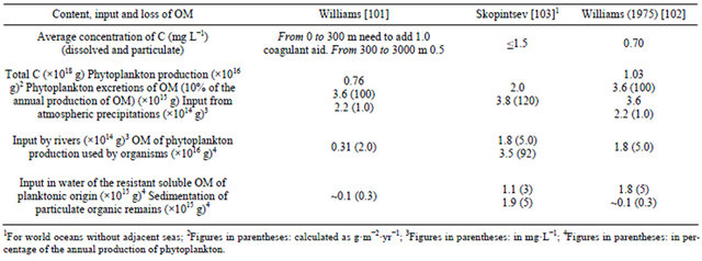
Table 8. Elements of the annual balance of OM in the water of the world ocean (in carbon) [88].
average of 0.051.
The annual amount of the terrigenous water humus entering rivers might have been overestimated as a result of: 1) its partial coagulation by the salts of the sea water, and 2) its extensive oxidation in the presence of decomposing remains of plankton. The latter phenomenon has been reported by many authors [88]. According to Sholkovitz [105], only 3% - 11% of dissolved OM from waters of four Scottish rivers when mixed with sea water flocculated within half an hour. The humic acid (HA) content (colorimetrically determined) of river waters was 4% - 20% of the total OM. Fulvic acid and possibly nonhumic compounds amounted to 80% - 90%. Fulvic acids form water-soluble compounds with Ca2+ and Mg2+; a large proportion of the HA would have aggregated in the mixing zones between river and sea water. According to calculations, approximately 60% of the total HA content coagulated in these experiments.
3.1.2. Natural Coagulation of River Water Humus in Seawater
Colloidal properties are characteristic of humic compounds of river waters. Owing to their aggregation, the colour of the filtered water decreased only by 10% - 25% of its initial value, which indicates only a partial removal of OM of river water on mixing with sea water. At the same time, the concentrations of the elements Fe, Mn, A1 and P in the water were markedly decreased (relative to their initial content). Similar results were obtained by Sholkovitz et al. [106] during experiments carried out in the waters of two rivers, the Luce (Scotland) and the Amazon (Brazil). Rapid flocculation [23] was characteristic for the high molecular-weight fractions of HA. This resulted in an aggregation of 60% - 80% of HA within half an hour (this amount represented 34 % of the initial dissolved OM).
The results of these works are principally in agreement with earlier published data [88]. In these experiments filtered marsh water was mixed with sea water in various proportions. Whilst carrying out these experiments, the water was kept in the dark at room temperature. After 30 days the colour of the filtered (size = 1.5 μm) water with a salinity of 0.2‰ was 98% of the initial value. At a salinity of 28.9‰ the colour was equal to 70% of the initial value of 62˚ (colour grade). In a similar experiment after 200 days the colour of the filtered water with a salinity of 0.2‰ and 32.5‰ was 50% of the initial value (44˚); in such a continuous experiment a partial oxidation of the water humus might have taken place. The greatest rate of coagulation was observed on the first day. In some experiments with peat water, the coagulation effect was practically zero when a number of salts (CaCl2, MgCl2, MgSO4, and HCl) were introduced. Equal effects might be found by mixing of peat water with sea water. Another effect is caused by the load of suspended particles. As has been shown by experiments, coagulation (or aggregation) of suspended particles in sea water [88] is less effective at a low particulate load even when humic compounds are present.
Bordovsky [107] is right in his belief that HA of marine deposits is of autochthonous and allochthonous origin, the latter playing a minor role. Based on chemical investigations and isotope determinations of C in HA isolated from ocean sediments, Nissenbaum and Kaplan [108] do not agree with this point of view. The allochthonous HA [87] in the bottom sediments of the ocean is evidently at the limits of detection of the analytical methods employed. According to Table 9 the total annual input of water humus to the ocean constitutes 1.5 × 10¹⁵ g C, provided the distribution is proportional, this amounts to 1 μg C∙L−1.
3.2. Why Simulation of Seawater Distillation?
It is difficult to imagine anything more important to the
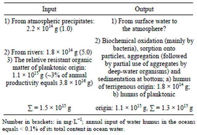
Table 9. Elements of the annual balance of OM in the water of the world ocean (in carbon) [88].
human population than safe drinking water [109]. Lack of clean drinking water is still the major cause of illness and death in young children in developing countries. In more fortunate communities, where water treatment is practiced [7], the primary aim of water authorities is to provide water that is free from pathogens and toxins. A secondary and very important objective is to provide water that is clear, colourless, and pleasant to taste. These latter objectives, while admirable, are often very difficult to achieve. Most countries now have water quality regulations, or guidelines, which are driving water authorities to produce purer water, with the minimum of contamination from natural or manmade origin. At the same time consumers are demanding that chemicals [9] added during the treatment of drinking water be kept to a minimum. As a consequence, conventional clarification methods are being challenged to comply with the new regulations and restrictions and our understanding of the mechanisms involved is being tested as never before [110].
Drinking water is produced from sources such as lakes, rivers, reservoirs (surface waters) or is abstracted from below the surface (groundwater) [26]. In all cases the water is affected by the external environment. Surface and ground waters [26] contain dissolved, colloidal and large particulate materials, which are composed of minerals or NOM from the terrestrial and aqueous environments. Also present are small organisms such as bacteria, algae, protozoa and diatoms [90,93]. In many instances micro-contaminants from human origin are present. These include industrial and agricultural chemicals [9], pharmaceuticals and personal care products. It is inevitable that in the next few years our raw water supplies will be further contaminated by the products of the burgeoning nano-technological industries that are generating advanced materials for drug delivery, catalysis, energy storage devices and sensors, amongst others. Whilst it is the ability to engineer these materials at the molecular level which bestows their unique properties and functions, it is this reduced size and vastly enhanced surface area that will also challenge our existing treatment technologies [110].
The result of all these natural and anthropogenic activities is that our typical raw water is a complex “soup” that often requires a range of treatment processes for the achievement of water quality targets. Once those objectives have been met at the water treatment plant [7], the water is distributed through a series of pipes of various types and sizes to the consumer tap. Almost every step of the journey from source to consumer tap involves some sort of interaction at a surface or an interface. Therefore an understanding of the processes taking place at interfaces through the series of complex processes is vital for the provision of safe and palatable, drinking water [110].
Moreover, it is interesting to trace the history of water quality monitoring from the earliest times when colour (NOM, manganese) and turbidity (particulates) were the sole criteria, to more recent times when taste and odour (algal metabolites) have become important, to today when health [4] is the major determinant. Thus the water industry is now concerned with inorganics such as arsenic, organics such as endocrine disruptors and most recently microbiological contaminants, a good example of which is Cryptosporidium [5,110].
On the other hand, if we are invited to select two major challenges in water treatment industry [7] we will not hesitate to design: 1) using chemicals [9] in drinking water treatment processes and 2) NOM coagulability. An analysis of chemicals (Al, Cl2 and polyelectrolytes) addition to the raw water during its treatment in order to produce drinking water is well presented in the literature such as the cited handbooks in this review (e.g., [21, 111,112]). Apart from human actions, some basic truths of chemistry [113] must be kept in mind: 1) a chemical reaction is rarely complete and may have secondary reactions producing undesirable by-products (i.e., all chemical disinfectants produce inorganic and/or organic DBPs that may be of concern); 2) chemicals by their selves are toxic [9,114-119] and the reaction products are also toxic even at low levels which are always diminished by the updated standards [19]. Further, chemicals need always appropriate mixing conditions [44] and hydraulic retention times, e.g., C/F to assure their distribution, conversion, and selectivity which are technically and practically difficult to realise considering the complicated microbial and physico-chemical composition of the raw water. It is well known that:
1) OM in water is very toxic than supposed (it was well known since 1970s that OM can produce DBPs but recent studies have proven that humic substances (HS) are toxic by their selves as they can be responsible of Blackfoot Disease [120-123];
2) NOM present in the natural environment is of a complex nature (it would be a mistake just to focus entirely on one fraction of NOM and to assume that removal of this fraction will solve the problem of haloform formation) [10];
3) It has been shown that coagulant doses are controlled by NOM concentration rather than by turbidity [53];
4) The removal of OM using C/F is very difficult especially in its dissolved form which can encourage microbial growth [124].
Hence, water treatment using chemicals [7] is really and practically difficult to optimise technically and economically to safe drinking water. In this sense, Clark [125] and Ghernaout et al. [126] presented the concept of the greening of chemistry.
However, drinking water treatment is not from yesterday (Figure 12). God, The Great and The Perfect, uses distillation at the open sky to give perfect drinking water, satisfying all the qualities, to the world since at least The Adam and Eve’s First Day until the Last Day. Distillation process would be presented as the future water treatment technology since it does not use chemicals (so, it has not the residual chemicals and their by-products problems) and its efficiency had been proven since the humankind dawn at the great scale. Furthermore, distillation technology is well known and developed in seawater desalination [68].
On the other hand, we may organise water treatment technologies (Table 10) into three general areas [12]:
• Physical methods• Chemical methods, and
• Energy intensive methods (such as distillation [15]).
All three of these technology groups can be combined in water treatment, or they may be used in select combinations depending upon the objectives of water treatment [12]. A good review of water treatment technologies is presented by Cheremisinoff [12].
3.3. Models of Oceanic Plankton Aggregation
Two of the most fundamental properties of any particle, inert or living, are its length and its mass. These two properties determine how a particle interacts with planktonic organisms as food or habitat, how it affects light, and how fast it sinks. Because organisms are discrete entities, particle processes affect them as well as nonliving material [127].
Life in the ocean coexists with two competing physical processes favouring surface and bottom of the ocean: light from above provides the energy to fuel the system; gravity from below collects essential materials encapsulated in particles. Coagulation is the formation of single, larger, particles by the collision and union of two smaller particles; very large particles can be made from smaller particles by multiple collisions. Coagulation makes big-
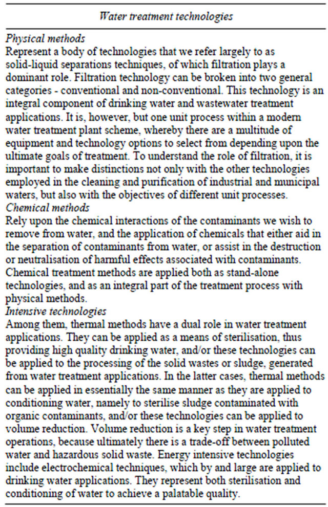
Table 10. Water treatment technologies [12].
ger particles, enhances sinking rates, and accelerates the removal of photosynthate. One result is that coagulation can limit the maximum phytoplankton concentration in the euphotic zone [127].
Particle size distributions have been measured since the advent of the Coulter Counter in the early 1970s, when researchers [127] reported on size distributions predominantly from surface waters around the world. They reported values for particles ostensibly between 1 and 1000 μm, although sampling and instrumental consideration suggest that the range was significantly smaller [127].
3.4. The Effects of Dissolved Salts
Any substance dissolved in a liquid has the effect of increasing the density of that liquid [128]. The greater the amount dissolved, the greater the effect. Water is no exception. The density of freshwater is close to 1.00 × 10³ kg∙m−3, while the average density of seawater [129] is about 1.03 × 10³ kg∙m−3.
Another important effect of dissolved substances is to depress the freezing point of liquids. For example, the
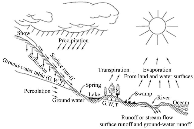
Figure 12. The hydrologic cycle [7].
addition of common salt (sodium chloride, NaCl) lowers the freezing point of water-which is why salt is spread on frozen roads. It also lowers the temperature at which water reaches its maximum density. That is because dissolved salts inhibit the tendency of water molecules to form ordered groups, so that density is controlled only by the thermal expansion effect. The oceans have high salinity, about 35 g∙kg−1 on average (of which about 30 g kg-1 are contributed by dissolved sodium ions (Na+, ~11 g) and chloride ions (Cl−, ~19 g)). Therefore, the density of seawater [129] increases with falling temperature right down to the freezing point. This is a crucial distinction between freshwater and seawater and it has a profound effect on the formation of sea-ice and on oceanic circulation processes [128].
4. Conclusions
This review concerns the concept of the best available technology of water/wastewater treatment and seawater desalination which is in fact a simulation of the seawater distillation at the open sky: coagulation in salty water aerated basin/coagulation using seawater as coagulant solution with distillation using stored solar energy followed by waterfall on a natural mountain. This natural, green, and technico-economical technology is composed of three steps: the first one is coagulation which may be achieved:
1) In salty water aerated basin (AS and DAF) where the raw water is “diluted” in seawater or;
2) In “conventional” coagulation using seawater as coagulant solution instead of alum/ferric salts.
The first option seems to be more natural as it simulates river water dilution in seawater and the second one is more practical for “rapid” water consummation. For colloids and microorganisms’ removal, double-layer compression and charge neutralisation, as main coagulation and disinfection mechanisms, would be involved in the first and second options, respectively. Aerated basin (AS/ DAF) reproduces the natural aeration to simulate healthy natural water basin. Using stored solar energy, distillation as the best liquid-solid/liquid-liquid separation process provides the removal of dissolved pollutants. For well balanced calco-carbonic equilibrium, the last step of this green treatment is the waterfall on a natural mountain providing useful gases, dissolved oxygen and carbon dioxide, and mineral salts to the water.
REFERENCES
- J. J. de Vries, “History of Groundwater Hydrology,” In: J. W. Delleur, Ed., The Handbook of Groundwater Engineering, Ch. 1, 2nd Edition, CRC Press, Taylor & Francis Group, Boca Raton, 2007.
- I. R. Falconer, “Cyanobacterial Toxins of Drinking Water Supplies, Cylindrospermopsins and Microcystins,” CRC Press, Taylor & Francis e-Library, Boca Raton, 2005.
- N. F. Gray, “Water Technology, an Introduction for Environmental Scientists and Engineers,” 2nd Edition, Elsevier Science & Technology Books, London, 2005.
- J. A. Salvato Jr., “Environmental Health,” In: J. R. Pfafflin and E. N. Ziegler, Eds., Encyclopedia of Environmental Science and Engineering, 5th Edition, CRC Press, Taylor & Francis Group, Boca Raton, 2006, p. 334.
- R. Fayer, “General Biology,” In: R. Fayer and L. Xiao, Eds., Cryptosporidium and Cryptosporidiosis, Ch. 1, 2nd Edition, CRC Press, Taylor & Francis Group, Boca Raton, 2008.
- A. D. Russell and P. J. Ditchett, “Disinfection,” In: J. R. Pfafflin and E. N. Ziegler, Eds., Encyclopedia of Environmental Science and Engineering, 5th Edition, CRC Press, Taylor & Francis Group, Boca Raton, 2006, p. 224.
- P. H. Jones and M. A. Tompeck, “Water Treatment,” In: J. R. Pfafflin and E. N. Ziegler, Encyclopedia of Environmental Science and Engineering, 5th Edtion, CRC Press, Taylor & Francis Group, Boca Raton, 2006, p. 1311.
- P. D. Cohn, M. Cox and P. S. Berger, “Health and Aesthetic Aspects of Water Quality,” In: R. D. Letterman, Tech. Ed., Water Quality and Treatment, a Handbook of Community Water Supplies, Ch. 2, 5th Edition, McGrawHill, Inc., New York, 1999.
- P. Baham and J. R. Pfafflin, “Effects of Chemicals,” In: J. R. Pfafflin and E. N. Ziegler, Eds., Encyclopedia of Environmental Science and Engineering, 5th Edition, CRC Press, Taylor & Francis Group, Boca Raton, 2006, p. 271.
- D. Ghernaout, B. Ghernaout and A. Kellil, “NOM Removal and Enhanced Coagulation as a Link between Coagulation and Electrocoagulation,” Desalination and Water Treatment, Vol. 2, No. 1-3, 2009, pp. 203-222. doi:10.5004/dwt.2009.116
- B. A. Dempsey, “Coagulant Characteristics and Reactions,” In: G. Newcombe and D. Dixon, Eds., Interface Science in Drinking Water Treatment, Theory and Applications, Ch. 2. In: A. Hubbard, Series Ed., Interface Science and Technology, Vol. 10, Academic Press, Elsevier, Amsterdam, 2006.
- N. P. Cheremisinoff, “Handbook of Water and Wastewater Treatment Technologies,” Butterworth-Heinemann, A Member of the Reed Elsevier Group, Boston, 2002.
- C. Tien, “Introduction to Cake Filtration, Analyses, Experiments and Applications,” Elsevier, Amsterdam, 2006.
- K. Sutherland, “Filters and Filtration Handbook,” 5th Edtion, Butterworth-Heinemann, Elsevier, Oxford, 2008.
- J. F. Richardson, J. H. Harker and J. R. Backhurst, “Coulson and Richardson’s Chemical Engineering,” In: R. K. Sinnott, Particle Technology and Separation Processes, Vol. 2, 5th Edition, Butterworth-Heinemann, an Imprint of Elsevier Science, Oxford, 2002.
- D. A. Nield, “Modelling Fluid Flow in Saturated Porous Media and at Interfaces,” In: D. B. Ingham and I. Pop, Eds., Transport Phenomena in Porous Media II, Ch. 1, Pergamon, an Imprint of Elsevier Science, Amsterdam, 2002.
- F. N. Kemmer (Ed.), “The NALCO Water Handbook,” 2nd Edtion, McGraw-Hill Book Company, New York, 1988.
- P. J. Delphos and G. M. Wesner, “Mixing, Coagulation, and Flocculation,” In: E. E. Baruth, Tech. Ed., Water Treatment Plant Design, American Water Works Association, American Society of Civil Engineers, Ch. 6, 4th Edition, McGraw-Hill, Inc., New York, 2005.
- D. Ghernaout, M. W. Naceur and A. Aouabed, “On the Dependence of Chlorine by-Products Generated Species Formation of the Electrode Material and Applied Charge during Electrochemical Water Treatment,” Desalination, Vol. 270, No. 1-3, 2011, pp. 9-22. doi:10.1016/j.desal.2011.01.010
- F. R. Spellman, “Water Treatment Operations and Unit Processes,” In: F. R. Spellman, Handbook of Water and Wastewater Treatment Plant Operations, Ch. 17, CRC Press, Boca Raton, 2003.
- J. De Zuane, “Handbook of Drinking Water Quality,” 2nd Edition, John Wiley & Sons, Inc., New York, 1997.
- J. E. Dyksen, “Aeration and Air Stripping,” In: E. E. Baruth, Tech. Ed., Water Treatment Plant Design, American Water Works Association, American Society of Civil Engineers, Ch. 5, 4th Edition, McGraw-Hill, Inc., New York, 2005.
- A. Anzalone, J. K. Bewtra and H. I. Ali, “Physical and Chemical Treatment of Wastewaters,” In: J. R. Pfafflin and E. N. Ziegler, Eds., Encyclopedia of Environmental Science and Engineering, 5th Edition, CRC Press, Taylor & Francis Group, Boca Raton, 2006, p. 972.
- D. W. Hand, D. R. Hokanson and J. C. Crittenden, “Air Stripping and Aeration,” In: R. D. Letterman, Tech. Ed., Water Quality and Treatment, a Handbook of Community Water Supplies, American Water Works Association, Ch. 5, 5th Edition, McGraw-Hill, Inc., New York, 1999.
- A. Stoddard, J. B. Harcum, J. T. Simpson, J. R. Pagenkopf and R. K. Bastian, “Municipal Wastewater Treatment: Evaluating Improvements in National Water Quality,” John Wiley & Sons, Inc., New York, 2002.
- P. Chan, Y. Ding and J. R. Schuring Jr., “Groundwater Resources,” In: J. R. Pfafflin and E. N. Ziegler, Eds., Encyclopedia of Environmental Science and Engineering, 5th Edition, CRC Press, Taylor & Francis Group, Boca Raton, 2006, p. 439.
- T. Asano, F. L. Burton, H. L. Leverenz, R. Tsuchihashi and G. Tchobanoglous, “Water Reuse: Issues, Technologies, and Applications,” Metcalf & Eddy, Inc., The McGraw-Hill companies, New York, 2007.
- H. F. Hemond and E. J. Fechner-Levy, “Chemical Fate and Transport in the Environment,” 2nd Edition, Academic Press, San Diego, 2008.
- W. W. Eckenfelder Jr., “Industrial Water Pollution Control,” 3rd Edition, McGraw-Hill Companies, Inc., New York, 2000.
- G. Tchobanoglous, F. L. Burton and H. D. Stensel, “Wastewater Engineering, Treatment and Reuse,” 4th Edition, Metcalf & Eddy, Inc., McGraw-Hill Companies, Inc., New York, 2003.
- D. Ghernaout and M. W. Naceur, “Ferrate(VI): In Situ Generation and Water Treatment–A Review,” Desalination and Water Treatment, Vol. 30, No. 1-3, 2011, pp. 319- 332. doi:10.5004/dwt.2011.2217
- A. Rushton, A. S. Ward and R. G. Holdich, “Solid-Liquid Filtration and Separation Technology,” VCH Verlagsgesellschaft Mbh, Weinheim, 1996.
- R. D. Letterman, A. Amirtharajah and C. R. O’Melia, “Coagulation and Flocculation,” In: R. D. Letterman, Tech. Ed., Water Quality and Treatment, a Handbook of Community Water Supplies, American Water Works Association, Ch. 6, 5th Edition, McGraw-Hill, Inc., New York, 1999.
- R. Beckett and J. Ranville, “Natural Organic Matter,” In: G. Newcombe and D. Dixon, Eds., Interface Science in Drinking Water Treatment, Theory and Applications, Ch. 17. In: A. Hubbard, Series Ed., Interface Science and Technology, Vol. 10, Academic Press, Elsevier, Amsterdam, 2006.
- A. I. Schäfer, “Natural Organics Removal Using Membranes, Principles, Performance and Cost,” Technomic Publishing Company, Inc., Lancaster, Pennsylvania, 2001.
- J. E. Smith Jr., R. C. Renner, B. A. Hegg and J. H. Bender, “Upgrading Existing or Designing New Drinking Water Treatment Facilities,” Noyes Data Corporation, Park Ridge, 1991.
- W. Lick, “Sediment and Contaminant Transport in Surface Waters,” CRC press, Taylor & Francis Group, Boca Raton, 2009.
- J. G. Farmer and M. C. Graham, “Freshwaters,” In: R. M. Harrison, Ed., Understanding Our Environment, an Introduction to Environmental Chemistry and Pollution, Ch. 3, 3rd Edition, Royal Society of Chemistry, Cambridge, 1999.
- H. L. Shorney, “Disinfection by-Product Precursor Removal by Enhanced Softening and Coagulation,” Ph.D. Thesis, University of Kansas, Lawrence, 1998.
- G. Lagaly, “From Clay Mineral Crystals to Colloidal Clay Mineral Dispersions,” In: H. Stechemesser and B. Dobiáš, Eds., Coagulation and flocculation, Ch. 8, 2nd Edition, Taylor & Francis Group, Boca Raton, 2005.
- B. A. Bolto, “Coagulation and Flocculation with Organic Polyelectrolytes,” In: G. Newcombe and D. Dixon, Eds., Interface Science in Drinking Water Treatment, Theory and Applications, Ch. 5. In: A. Hubbard, Series Ed., Interface Science and Technology, Vol. 10, Academic Press, Elsevier, Amsterdam, 2006.
- M. R. Wiesner, M. M. Clark and J. Mallevialle, “Membrane Filtration of Coagulated Suspensions,” Journal of Environmental Engineering, Vol. 115, No. 1, 1989, pp. 20-40. doi:10.1061/(ASCE)0733-9372(1989)115:1(20)
- K. O. Nowack and F. S. Cannon, “Ferric Chloride plus GAC for Removing TOC,” Proceedings of the AWWA Water Quality Technology Conference, Boston, 17-21 November 1996, pp. 65-78.
- J. Gregory, “Floc Formation and Floc Structure,” In: G. Newcombe and D. Dixon, Eds., Interface science in drinking water treatment, theory and applications, Ch. 3. In: A. Hubbard, Series Ed., Interface Science and Technology, Vol. 10, Academic Press, Elsevier, Amsterdam, 2006.
- J. F. Atkinson, R. K. Chakraborti and J. E. VanBenschoten, “Effects of Floc Size and Shape in Particle Aggregation,” In: I. G. Droppo, G. G. Leppard, S. N. Liss and T. G. Milligan, Eds., Flocculation in Natural and Engineered Environmental Systems, Ch. 5, CRC Press, Boca Raton, 2005.
- J. L. Cleasby, A. H. Dharmarajah, G. L. Sindt and E. R. Baumann, “Design and Operations Guidelines for Optimization of the High-Rate Filtration Process: Plant Survey Results,” Final Project Report, AWWA and AWWA Research Foundation, Denver, 1989.
- N. K. Shammas, “Coagulation and Flocculation,” In: L. K. Wang, Y.-T. Hung and N. K. Shammas, Eds., Handbook of Environmental Engineering, Physicochemical Treatment Processes, Vol. 3, Ch. 4, The Humana Press Inc., Totowa, 2005.
- F. Woodard, “Industrial Waste Treatment Handbook,” Butterworth–Heinemann, Boston, 2001.
- C. N. Sawyer, P. L. McCarty and G. E. Parkin, “Chemistry for Environmental Engineering,” 4th Edition, McGraw-Hill, New York, 1994.
- T. D. Reynolds, “Unit Operations and Processes in Environmental Engineering,” Brooks/Cole Engineering Division, Monterey, 1982.
- J. H. Masliyah and S. Bhattacharjee, “Electrokinetic and Colloid Transport Phenomena,” John Wiley & Sons, Inc., Hoboken, 2006.
- H. S. Weinberg, V. J. Pereira and Z. Ye, “Drugs in Drinking Water Treatment Options,” In: D. S. Aga, Ed., Fate of Pharmaceuticals in the Environment and in Water Treatment Systems, Ch. 10, CRC Press, Taylor & Francis Group, Boca Raton, 2008.
- K. J. Wilkinson and A. Reinhardt, “Contrasting Roles of Natural Organic Matter on Colloidal Stabilization and Flocculation in Freshwaters,” In: I. G. Droppo, G. G. Leppard, S. N. Liss and T. G. Milligan, Flocculation in Natural and Engineered Environmental Systems, Ch. 7, CRC Press, Boca Raton, 2005.
- D. J. Pernitsky, “Coagulation 101,” P:\OFFICE\Conferences\2003TechTrans\Dave P\DAVE_paper.doc (consulted 25/07/05).
- D. Ghernaout and B. Ghernaout, “Sweep Flocculation as a Second Form of Charge Neutralisation—A Review,” Desalination and Water Treatment, Vol. 44, No. 1-3, 2012, pp. 15-28.doi:10.1080/19443994.2012.691699
- E. J. W. Verwey and J. Th. G. Overbeek, “Theory of the Stability of Lyophobic Colloids,” Elsevier, Amsterdam, 1948.
- C. R. O’Melia, “Fundamentals of Particle Stability,” In: G. Newcombe and D. Dixon, Eds., Interface Science in Drinking Water Treatment, Theory and Applications, Ch. 18. In: A. Hubbard, Series Ed., Interface Science and Technology, Vol. 10, Academic Press, Elsevier, Amsterdam, 2006.
- D. J. Shaw, “Introduction to Colloid and Surface Chemistry,” 4th Edition, Butterworth-Heinemann, an Imprint of Elsevier Science, Oxford, 1992.
- R. M. Pashley and M. E. Karaman, “Applied Colloid and Surface Chemistry,” John Wiley & Sons, Ltd., Chichester, 2004. doi:10.1002/0470014709
- [61] K. J. Ives, “Coagulation and Flocculation, Part II-Orthokinetic Flocculation,” In: L. Svarovsky, Ed., Solid-Liquid Separation, 4th Edition, Butterworth-Heine-mann, Oxford, 2000.
- [62] S. N. Liss, T. G. Milligan, I. G. Droppo and G. G. Leppard, “Methods for Analyzing Floc Properties,” In: I. G. Droppo, G. G. Leppard, S. N. Liss and T. G. Milligan, Eds., Flocculation in Natural and Engineered Environmental Systems, Ch. 1, CRC Press, Boca Raton, 2005.
- [63] T. Beveridge, “Large-Scale Centrifugation,” In: I. D. Wilson, E. R. Adlard, M. Cooke and C. F. Poole, Encyclopedia of Separation Science, Academic Press, London, 2000, pp. 320-342.
- [64] S. Takahide, “Kurita Handbook of Water Treatment,” 2nd Edition, Kurita Water Industries, Ltd., Tokyo, 1999.
- [65] J. Criddle, “A Review of the Mammalian and Aquatic Toxicity of Polyelectrolytes,” Report NR 2545, Foundation for Water Research, Medmenham, 1990.
- [66] M. F. Doherty, Z. T. Fidkowski, M. F. Malon and R. Taylor, “Distillation (Section 13), Perry’s Chemical Engineering Handbook,” 8th Edition, McGraw-Hill Companies, Inc., New York, 2008.
- [67] Z. Lei, B. Chen and Z. Ding, “Special Distillation Processes,” Elsevier, Amsterdam, 2005.
- [68] R. K. Sinnott, “Separation Columns (Distillation, Absorption and Extraction),” In: R. K. Sinnott, Coulson and Richardson’s Chemical Engineering, Vol. 6, Ch. 11, 4th Edition, Elsevier Butterworth-Heinemann, Oxford, 2005.
- [69] H. T. El-Dessouky and H. M. Ettouney, “Fundamentals of Salt Water Desalination,” Elsevier, Amsterdam, 2002.
- [70] G. Towler and R. Sinnott, “Chemical Engineering Design, Principles, Practice and Economics of Plant and Process Design,” Elsevier Inc., Amsterdam, 2008.
- [71] F.-W. Möllenkamp, “Energy Sources—Alternatives,” In: J. R. Pfafflin and E. N. Ziegler, Eds., Encyclopedia of Environmental Science and Engineering, 5th Edition, CRC Press, Taylor & Francis Group, Boca Raton, 2006, p. 295.
- [72] H. Silla, “Chemical Process Engineering, Design and Economics,” Marcel Dekker, Inc., Taylor & Francis Group, New York, 2003.
- [73] P. S. Buckley, W. L. Luyben and J. P. Shunta, “Design of Distillation Column Control Systems,” Creative Services Inc., New York, 1985.
- [74] R. Smith, M. Jobson, “Distillation,” In: I. D. Wilson, E. R. Adlard, M. Cooke, C. F. Poole, Eds., Encyclopedia of Separation Science, Academic Press, London, 2000.
- [75] R. Smith, “Chemical Process Design,” McGraw-Hill, Inc., New York, 1995.
- [76] J. R. Fair, “Distillation,” In: L. F. Albright, Ed., Albright’s Chemical Engineering Handbook, Ch. 12, CRC Press, Taylor & Francis Group, Boca Raton, 2009.
- [77] D. Shekhawat and P. Srivastava, “Dissolved Air Flotation,” In: I. D. Wilson, E. R. Adlard, M. Cooke and C. F. Poole, Eds., Encyclopedia of Separation Science, Academic Press, London, 2000.
- [78] K. A. Matis and A. I. Zouboulis, “An Overview of the Process, In: K. A. Matis, Ed., Flotation Science and Engineering, Ch. 1, Marcel Dekker, Inc., New York, 1995.
- [79] J. K. Edzwald, “Dissolved Air Flotation in Drinking Water Treatment,” In: G. Newcombe and D. Dixon, Eds., Interface Science in Drinking Water Treatment, Theory and Applications, Ch. 5. In: A. Hubbard, Series Ed., Interface Science and Technology, Vol. 10, Academic Press, Elsevier, Amsterdam, 2006.
- [80] R. W. Crites, J. Middlebrooks and S. C. Reed, “Natural Wastewater Treatment Systems,” Taylor & Francis Group, Boca Raton, 2006.
- [81] J. R. Pfafflin, “Municipal Wastewater,” In: J. R. Pfafflin and E. N. Ziegler, Encyclopedia of Environmental Science and Engineering, 5th Edition, CRC Press, Taylor & Francis Group, Boca Raton, 2006, p. 727.
- [82] G. Bitton, “Wastewater Microbiology,” 3rd Edition, John Wiley & Sons, Inc., New York, 2005.
- [83] V. Vinceviciene, “Wastewater Regulation,” In: P. Quevauviller, O. Thomas and A. van der Beken, Eds., Wastewater Quality Monitoring and Treatment, Ch. 1.1, John Wiley & Sons, Ltd., Chichester, 2006.
- [84] R. E. Weiner and R. A. Matthews, “Environmental Engineering,” 4th Edition, Butterworth-Heinemann, Elsevier Science (USA), Amsterdam, 2003.
- [85] M. B. Hocking, “Handbook of Chemical Technology and Pollution Control,” 3rd Edition, Academic Press, an Imprint of Elsevier, Amsterdam, 2005.
- [86] A. R. Jantrania and M. A. Gross, “Advanced Onsite Wastewater Systems Technologies,” CRC Press, Taylor & Francis Group, Boca Raton, 2006.
- [87] E. Delyannis and V. Belessiotis, “Desalination,” In: J. R. Pfafflin and E. N. Ziegler, Eds., Encyclopedia of Environmental Science and Engineering, 5th Edition, CRC Press, Taylor & Francis Group, Boca Raton, 2006, p. 194.
- [88] L. Thomsen, “Organic Rich Aggregates in the Ocean: Formation, Transport Behavior, and Biochemical Composition,” In: I. G. Droppo, G. G. Leppard, S. N. Liss and T. G. Milligan, Eds., Flocculation in Natural and Engineered Environmental Systems, Ch. 11, CRC Press, Boca Raton, 2005.
- [89] B. A. Skopintsev, “Decomposition of Organic Matter of Plankton, Humification and Hydrolysis,” In: E. K. Duursma and R. Dawson, Eds., Marine Organic Chemistry, Evolution, Composition, Interactions and Chemistry of Organic Matter in Seawater, Ch. 6. In: Elsevier Oceanography Series, Vol. 31, Elsevier Scientific Publishing Company, Amsterdam, 1981, pp. 125-177.
- [90] E. Kreps, “Organic Catalysts or Enzymes in Sea Water,” In: A. E. Daniel, Ed., James Johnston Memorial, Liverpool University Press, Liverpool, 1934, pp. 193-202.
- [91] A. Krogh, “Conditions of Life at Great Depth in the Ocean,” Ecological Monographs, Vol. 4, No. 4, 1934, pp. 430-439.doi:10.2307/1961649
- [92] M. M. Kononova, “Organic Matter of Soil,” Izvestija. Akademija Nauk SSSR, Moscow, 1963.
- [93] M. G. Rutten, “The Origin of the Life by Natural Causes,” Elsevier, Amsterdam, 1971.
- [94] B. Ghernaout, D. Ghernaout and A. Saiba, “Algae and Cyanotoxins Removal by Coagulation/Flocculation: A Review,” Desalination and Water Treatment, Vol. 20, No. 1-3, 2010, pp. 133-143. doi:10.5004/dwt.2010.1202
- [95] D. Ghernaout and B. Ghernaout, “On the Concept of the Future Drinking Water Treatment Plant: Algae Harvesting from the Algal Biomass for Biodiesel Production––A Review,” Desalination and Water Treatment, Vol. 49, No. 1-3, 2012, pp. 1-18. doi:10.1080/19443994.2012.708191
- [96] S. Oden, “Die Huminsiiuren,” Kolloidchemische Beihefte, Vol. 11, No. 3-9, 1919, pp. 75-260. doi:10.1007/BF02557436
- [97] O. Aschan, “Om Wattenhumus Och Dess Medverkan Vid Sjomalms Bildingen,” Arch. Kemi, Mineral. Geol, Vol. 10A, 1932, pp. 1-143.
- [98] K. Kalle, “The Problem of the Gelbstoff in the Sea,” Oceanography and Marine Biology. An Annual Review, Vol. 4, 1966, pp. 91-104.
- [99] B. A. Birge and C. Juday, “Particulate and Dissolved Organic Matter in Inland Waters,” Ecological Monographs, Vol. 4, No. 4, 1934, pp. 440-474. doi:10.2307/1961650
- [100] S. A. Waksman, “Humus,” Bailliere, Tindall and Cox, London, 1936.
- [101] E. Odum, “The Essentials of Ecology,” Nauka, Moscow, 1975.
- [102] P. M. Williams, “The Distribution and Cycling of Organic Matter in the Ocean,” In: S. D. Faust and I. P. Hunter, Eds., Organic Compounds in Aquatic Environment, Marcel Dekker, New York, 1971, pp. 145-163,.
- [103] P. J. le B. Williams, “Biological and Chemical Aspects of Dissolved Organic Material in Sea Water,” In: J. P. Riley and G. Skirrow, Eds., Chemical Pceanography, Vol. 2, 2nd Edition, Academic Press, London, 1975, pp. 301-363.
- [104] B. A. Skopintsev, “Recent Progress in Study of Organic Matter in Ocean Water,” Okeanologiya, Vol. 11, 1971, pp. 939-956.
- [105] R. A. Duce and E. K. Duursma, “Inputs of Organic Matter to the Ocean,” Marine Chemistry, Vol. 5, No. 4-6, 1977, pp. 319-339. doi:10.1016/0304-4203(77)90027-5
- [106] E. R. Sholkovitz, “Flocculation of Dissolved Organic and Inorganic Matter during the Mixing of River Water and Sea Water,” Geochimica et Cosmochimica Acta, Vol. 40, No. 7, 1976, pp. 831-845. doi:10.1016/0016-7037(76)90035-1
- [107] E. R. Sholkovitz, E. A. Boyle and N. B. Price, “The Removal of Dissolved Humic Acids and Iron during Estuarine Mixing,” Earth and Planetary Science Letters, Vol. 40, No. 1, 1978, pp. 130-136. doi:10.1016/0012-821X(78)90082-1
- [108] O. K. Bordovsky, “Organic Matter of Sea and Ocean Sediments in the Stage of Early Diagenesis,” Nauka, Moscow, 1974.
- [109] A. Nissenbaum and J. Kaplan, “Chemical and Isotopic Evidence of in Situ Origin of Marine Humic Substances,” Limnology and Oceanography, Vol. 17, No. 4, 1972, pp. 570-582. doi:10.4319/lo.1972.17.4.0570
- [110] G. Newcombe and D. Dixon, “Preface,” In: G. Newcombe and D. Dixon, Eds., Interface Science in Drinking Water Treatment, Theory and Applications, In: A. Hubbard, Series Ed., Interface Science and Technology, Vol. 10, Academic Press, Elsevier, Amsterdam, 2006.
- [111] G. Newcombe and D. Dixon, “Introduction,” In: G. Newcombe and D. Dixon, Eds., Interface Science in Drinking Water Treatment, Theory and Applications, Ch. 1. In: A. Hubbard, Series Ed., Interface Science and Technology, Vol. 10, Academic Press, Elsevier, Amsterdam, 2006.
- [112] E. R. Alley, “Water Quality Control Handbook,” 2nd Edition, McGraw-Hill Companies, Inc., New York, 2007.
- [113] J. T. O’Connor, T. O’Connor and R. Twait, “Water Treatment Plant Performance Evaluations and Operations,” John Wiley & Sons, Inc., New York, 2009. doi:10.1002/9780470431474
- [114] W. Stumm, M. Forsberg and S. Gherini, “Water Chemistry,” In: J. R. Pfafflin and E.N. Ziegler, Eds., Encyclopedia of Environmental Science and Engineering, 5th Edition, CRC Press, Taylor & Francis Group, Boca Raton, 2006, p. 1256.
- [115] A. Becaria, D. K. Lahiri, S. C. Bondy, D. Chen, A. Hamadeh, H. Li, R. Taylor and A. Campbell, “Aluminum and Copper in Drinking Water Enhance Inflammatory or Oxidative Events Specifically in the Brain,” Journal of Neuroimmunology, Vol. 176, No. 1, 2006, pp. 16-23. doi:10.1016/j.jneuroim.2006.03.025
- [116] J. R. Walton, “A Longitudinal Study of Rats Chronically Exposed to Aluminium at Human Dietary Levels,” Neuroscience Letters, Vol. 412, No. 1, 2007, pp. 29-33. doi:10.1016/j.neulet.2006.08.093
- [117] C. Gourier-Fréry and N. Fréry, Aluminium, EMC-Toxicologie-Pathologie, Vol. 1, No. 3, 2004, pp. 79-95. doi:10.1016/j.emctp.2004.04.002
- [118] T. P. Flaten, “Aluminium as a Risk Factor in Alzheimer’s Disease, with Emphasis on Drinking Water,” Brain Research Bulletin, Vol. 55, No. 2, 2001, pp. 187-196. doi:10.1016/S0361-9230(01)00459-2
- [119] L. Lévesque, C. A. Mizzen, D. R. McLachlan and P. E. Fraser, “Ligand Specific Effects on Aluminum Incorporation and Toxicity in Neurons and Astrocytes,” Brain Research, Vol. 877, No. 2, 2000, pp. 191-202. doi:10.1016/S0006-8993(00)02637-8
- [120] E. Gauthier, I. Fortier, F. Courchesne, P. Pepin, J. Mortimer and D. Gauvreau, “Aluminum Forms in Drinking Water and Risk of Alzheimer’s Disease,” Environmental Research, Vol. 84, No. 3, 2000, pp. 234-246. doi:10.1006/enrs.2000.4101
- [121] M.-L. Cheng, H.-Y. Ho, D. T.-Y. Chiu, F.-J. Lu, “HA-Mediated Oxidative Damages to Human Erythrocytes: A Possible Mechanism Leading to Anemia in Blackfoot Disease,” Free Radical Biology Medicine, Vol. 27, No. 3-4, 1999, pp. 470-477. doi:10.1016/S0891-5849(99)00072-6
- [122] C.-H. Tseng, “Blackfoot Disease and Arsenic: A NeverEnding Story,” Journal of Environmental Science and Health, Vol. 23, 2005, pp. 55-74.
- [123] R.-J. Gau, H.-L. Yang, J.-L. Suen and F.-J. Lu, “Induction of Oxidative Stress by HA through Increasing Intracellular Iron: A Possible Mechanism Leading to Atherothrombotic Vascular Disorder in Blackfoot Disease,” Biochemical and Biophysical Research Communications, Vol. 283, No. 4, 2001, pp.743-749. doi:10.1006/bbrc.2001.4832
- [124] Y.-C. Hseu, H.-W. Huang, S.-Y. Wang, H.-Y. Chen, F.-J. Lu, R.-J. Gau and H.-L. Yang, “HA Induces Apoptosis in Human Endothelial Cells,” Toxicology and Applied Pharmacology, Vol. 182, No. 1, 2002, pp. 34-43. doi:10.1006/taap.2002.9429
- [125] J. E. Van Benschoten and J. K. Edzwald, “Chemical Aspects of Coagulation Using Aluminium Salts-II. Coagulation of Fulvic Acid Using Alum and Polyaluminum Chloride,” Water Research, Vol. 24, No. 12, 1990, pp. 1527- 1535.doi:10.1016/0043-1354(90)90087-M
- [126] J. H. Clark, “Introduction,” In: J. Clark and D. Macquarrie, Eds., Handbook of Green Chemistry and Technology, Ch. 1, Blackwell Science Ltd, Oxford, 2002.
- [127] D. Ghernaout, B. Ghernaout and M. W. Naceur, Embodying the Chemical Water Treatment in the Green Chemistry—A Review,” Desalination, Vol. 271, No. 1-3, 2011, pp. 1-10.doi:10.1016/j.desal.2011.01.032
- [128] G. A. Jackson, “Coagulation Theory and Models of Oceanic Plankton Aggregation,” In: I. G. Droppo, G. G. Leppard, S. N. Liss and T. G. Milligan, Eds., Flocculation in Natural and Engineered Environmental Systems, Ch. 13, CRC Press, Boca Raton, 2005.
- [129] E. Brown, A. Colling, D. Park, J. Phillips, D. Rothery and J. Wright, “Seawater: Its Composition, Properties and Behaviour,” 2nd Edition, Butterworth-Heinemann, Oxford, 2004.
- [130] K. S. Venkateswarlu, “Water Chemistry, Industrial and Power Station Water Treatment,” New Age International (P), Ltd., New Delhi, 1996.