International Journal of Geosciences
Vol.08 No.08(2017), Article ID:78851,24 pages
10.4236/ijg.2017.88059
Thermoelectric Currents of Earth’s Core Generate the Earth’s Magnetic Field
Arkadiy Nikolaevich Dmitriev
Tyumen Industrial University, Tyumen, Russia
![]()
Copyright © 2017 by author and Scientific Research Publishing Inc.
This work is licensed under the Creative Commons Attribution International License (CC BY 4.0).
http://creativecommons.org/licenses/by/4.0/


Received: July 31, 2017; Accepted: August 28, 2017; Published: August 31, 2017
ABSTRACT
The geotemperature gradient is considered as taking main part in generating the Earth’s magnetic field. It is shown that geotemperature gradient functions as a generator of both nuclear and mantle thermoelectrical currents thanks to the great temperature difference between the core and the mantle. The move- ment of those currents is close to the radial direction towards the Earth’s crust. However, the nuclear thermocurrents movement tends to cyclically change into opposite one. If the mantle and core thermocurrents move oppositely, the Earth’s crust cools down globally and ice age comes, but if they move unidirectionally then global warming comes. The calculation show that the Earth’s surface can warm up to not more than 10˚C. The latter, considering how human factor affects the warming of Earth, is incomparably great. There are calculations that show power of the Earth’s thermocurrents being enough to generate and maintain the Earth’s magnetic field, its modern dynamics and the poles inversion.
Keywords:
Geotemperature Gradient, Thermoelectrical Currents, Cyclic Thermocurrents, Inversion of the Magnetic Poles, Geothermoelectric Model of the Magnetic Field

1. Introduction
At the present time, the most elaborate theory of substantiating electrical currents generation in the planet’s metal core is based on hydromagnetic dynamo which works on the self-excitation principle. There are a lot of theoretical and experimental works to prove this model [1] - [6] . However, such model, able not only generate but also fully maintain the Earth’s magnetic field for a long while, needs some conditions to be met, such as low viscosity of the core metal fluid, convective vertical movements in it, raw magnetic field and so on.
Besides, based on the browsed professional reviews and works [2] - [9] it is obvious that there is still no fundamental and effective principle of generating the Earth’s dipole magnetic field for the hydromagnetic dynamo model.
Nevertheless, even in the first half of the last century there were attempts to explain the Earth’s magnetic field with thermoelectromotive forces existing in the core, which are conditioned by turbulent convective movements of the core’s liquid [10] [11] [12] . However, T. Rikitaki [1] considered those attempts as unlikely thermoelectrical effects, explaining this by absence of distinctness of the core’s thermoelectrical power. T. Rikitaki’s opinion turned out to be conclusive, since then all the researches of thermoelectrical effects were not taken into consideration in the dynamo theory.
There is another reminder of thermoelectrical currents’ role in forming magnetic fields of hot CP stars and, probably, planets in a work of A. Z. Dolginov, where the scientist got the equation of field generation [7] :
(1)
(where is thermoelectrical coefficient).
He thought that the forth from right member was different from zero and generated the star’s magnetic field, whereas the first three members could be neglected because they were small and could not be performed at the considered model of moving unmagnetized plasm. His calculations showed that the dipole field of a star on its surface can be about 10−4 T. Unfortunately, A. Z. Dolginov never presented a detailed theory of making magnetic fields of space objects with thermoelectrical currents, which are immanent to “hot” objects.
Below, there is the third attempt to reanimate geothermoelectrical currents below. It is shown on the example of Earth that those geothermocurrents, moving directionally inside the conducting shells (the core and the lower mantle) and affected by the great difference of geotemperatures, can generate not raw but real powerful magnetic fields of Earth and other “hot” planets of the solar system, because the phenomenon is universal.
That attempt is based on the results of geophysical field work for many years, experimental and academic research, which let the author elaborate a new model of thermo-electrochemical nature of the Earth’s core natural electric field [13] [14] . It is shown that the potential-forming factor of a natural electric field is not the reduction-oxidation zone, but a constantly functioning extraneous source of non-electric origin, which is geotemperature gradient ∂T/∂z. Affected by only the latter (∂T/∂z vector is always directed deep into the earth) the anomalies of the natural electric potential, registered at all the Earth’s continents, are steadily negative. Besides, only the geotemperature gradient forms two poles along the fall of natural electrical conductors: a negatively charged inner part of conductors and a positively charged outer one (positive pole) in the upper part of the poles, as well as positively charged inner part of conductors and the negatively charged outer one (negative pole) in the lower part of the poles. Thermoelectrical currents move inside conductors if the temperature difference applied to the ends of ore bodies is in dynamic state. If the state is static there is no thermoelecrical current, but there is still difference of potentials between the cold and the warmed ends of the conductor.
Hereinafter all the calculations of a planet’s magnetic field are based on the known physical laws and known scientific data of inner structure and physical properties of Earth. The results show that the actual Earth’s thermoelectrical currents generate and maintain the current geomagnetic field by themselves. Besides, it is the first time when a model specifies complexity of the geomagnetic field, which consists of two parts: main magnetic field of the metal core and additional field of the lower mantle.
Accordingly, the schematic geothermoelectrical model (protomodel) of the Earth’s magnetic field is considered for the first time in the author’s article [15] .
2. Calculations of Magnetic Field for the Lower Mantle
To form the geomagnetic model one should procced from the known scientific data of the planet’s shells thicknesses, temperature values in the shells and their borders. For example, most of the researchers hold on to the following defining temperatures in the body of our planet: on the depth of about 100 km the temperature is close +1800 K, on the depth of about 400 km (C layer, phase transition zone) the temperature is +1900 K, on the “mantle-core” border the temperature is +4000, …, +5000 K, in the core center the temperature is (+5000, …, +6230) ± 500 K [16] - [21] . As for the planet’s electroconductivity, the researchers believe it is distributed in depth (shells) as follows: the upper mantle has low electroconductivity and, predominantly, ionic conduction; in the C layer, semiconducting electroconductivity increases after transiting from the ionic conductivity; the lower’s mantle material is an electronic semiconductor; the Earth’s core is an electronic conductor with the specific conductance in the range of (0.1 ÷ 1.0) × 106 S・m−1 [16] [17] [21] [22] .
That data implies that the globe can be presented as a spherical geothermoelecrical element (further, SGTE) (Figure 1(a)), which ends are the central part of the core and the C shell (most likely, its middle). The temperature difference of about +3200 K, …, +4500 K is attached to those ends. Then, according to the Seebeck effect, the thermo-EMF ΔφТ can be calculated [23] [24] :
(2)
where β is the averaged temperature coefficient, which is 0.0001 V・deg−1. for pure metals, while it is 0.0015 V・deg−1. for some semiconductors [24] .
To find the parameters of the lower mantle thermocurrents Itop the following must be known:
- thermofield intensity ET;
- electron concentration per unit volume of the lower mantle ores (it equals n =
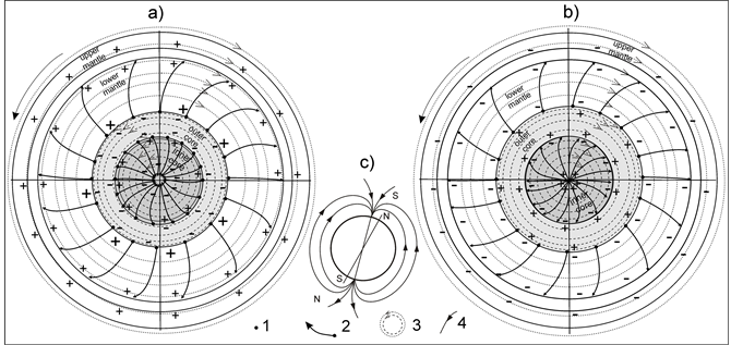
Figure 1. Scheme of the electron flows movement within the spherical metal core and the spherical circle of the lower mantle: (a) projection of traces of oppositely moving electrons of the metal core (to the core’s center) and the lower mantle (to the Earth’s surface) on the equatorial plane; (b) projection of traces of unidirectionally moving electrons of the metal core and the lower mantle to the Earth’s surface on the equatorial plane; (с) dipolar poloidal magnetic field of the Earth. 1: electron; 2: electron trajectories; 3: the lines of force of toroidal field; 4: the lines of force of self-generated poloidal field.
1020 m−3 by default);
- electron gas drift velocity ;
- electron mean free path in a semiconductor l;
- current density j.
According to the (2), the maximum thermo-EMF ΔφТ for SGTE is 0.45 V, and the electric field intensity can be found from the following equality:
; (3)
where is SGTE radius length, which equals the distance between the planet center and the middle part of the C shell and is defined as 5438 km or 5650 km to the upper mantle.
Hence, the electric field ЕТ generated by the existing temperature difference ΔТ makes planetary flows of “hot” electrons move directionally from the planet center to its outer shells along the radii. At the same time the electron quantity (concentration) in a volume unit of metal (Fe) can be calculated with the formula [24] :
, (4)
where ρ is the metal Fe density in the inner core, (12.2 g・cm−3); NA is the Avogadro constant, 6.02 × 10²³ mol−1; A is atomic mass Fe (55.847 g). Substituting that data into the (4) we get . n should be compared to the calculation for the real conditions when electron gas is in free state at pressures p, that corresponds to the metal core, i.e. at p = 3.55 million atm [25] [26] [27] :
(5)
Knowing that electron mass and a new magnitude can be found . Despite there is a slight discrepancy between magnitudes ni (just 2.5 times), the magnitude is used for the further calculations, as it meets the real planet conditions most. In its turn, the total sum of electron gas in the metal core is defined as
.
The same must be performed for the lower mantle, spherical shell circle thickness is , (average value for semiconductors from 5 × 10¹⁹ m−3 to 5 × 10²⁰ m−3 [28] ), the electron mass is the same. Then .
To calculate the electron gas drift velocity , according to the quantum theory of the electrical conductivity of metals, the following formula should be used [24] [26] [27] [29] [30] :
, (6)
where e is the effective electron charge, C (1.6 × 10⁻¹⁹); m is the effective electron mass, kg (0.91 × 10⁻³⁰); l is the electron mean free path, it equals
; (7)
where σ is the planet’s core electroconductivity, S/m;
ħ is the Plank’s constant, 1.05 × 10⁻³⁴, J・s;
is the average velocity of electrons thermal movement, it can be derived from the formula:
(8)
where k is the Boltzmann constant, 1.38 × 10⁻²³ J/K;
As seen, it is necessary to calculate the velocity of the electron thermal movement at T = 6000 K preliminary, according to (8), to calculate ЕТ and the electron mean free path
between their concussions with the crystal cell to find
.
directly depends on the metal core’s electroconductivity
The density of the lower mantle thermoelectrical currents j can be found from the formula, according to [24] [26] [27] [29] [30] [31] :
(9)
where is Fermi momentum, defined as:
(10)
Now the lower mantle thermocurrents Itop must be quantified, as well as the amplitude of the magnetic field they generate. The following must be taken into consideration: 1) the ores are semiconductors, 2) the specific conductance of the mantle solid ores (semiconductors) is a way lower than the core’s one, and it is 0.1 ÷ 10.0 S・m−1 [22] , but there is a more specific range (0.1 ÷ 1.0 S・m−1 [32] ) of its electroconductivity values, based on the inversion of the world net geomagnetic data, 3) according to the statistics, electron concentration in semiconductors is just 1020 m−3 [28] , generally.
Then the total value of the lower mantle thermocurrents Itop, coming through its outer spherical surface SD with the radius RD can be derived from the following formula:
, (11)
And, finally, according to the Biot-Savart-Laplace law, the Earth’s magnetic induction on the bottom surface equator can be calculated:
(12)
However, the magnetic moment of the current element is considered here only in a one-dimensional space towards the current movement along the radius . Integration over allows to find the total of the current elements just along the way . This won’t go for our case, when the radial currents, like Ilow, move from the source (sphere’s center) to the interface with the lower mantle spherical surface, directed azimuthally from 0 to 4π in a spherical conductor. There is no decision on valuation magnetic induction when currents move radially in a spherical conductor in technical literature.
That’s why it is better to consider the following model. A small spherical conductor with the radius is put into the spherical conductor with the radius . The currents, moving from the spheres center make a magnetic field in the volume of the initial small sphere. That field is always directed to its volumetric surface tangentially. Then, according to the circulation theorem,
where the currents , coming through the small
sphere surface . When the current is distributed evenly over the sphere’s
section . Hence, after substituting and shortening, here is the
Biot-Savart formula for calculating the magnetic field induction inside the sphere (metal core) as the following rationalized form:
or , (13)
where is the Earth’s radius, is the metal core radius.
In its turn, the magnetic field on the Earth’s surface for the lower mantle spherical layer can be calculated with considering the thickness of that layer ΔRD, which is denoted as in (12).
(14)
The heat Q, which is produced in the lower mantle Vlm because thermocurrents interact with active resistance of this mantle’s ores. It can be found from the following formula [23] :
(15)
where j is the current density in the lower mantle, A・m−2; σ is the lower mantle’s electroconductivity Sm−1; is the time of producing heat for 31,536,000 c (year); is the volume of the lower mantle’s spherical circle.
All the calculations for the lower mantle, including the used constants, are tabulated to Table 1.
As seen from the table, the value of the magnetic induction on the Earth’s surface is ~4.62 × 10⁻⁶ T, which is much lower than the really measured for the same terrestrial conditions . The heat Q, which is produced in the lower mantle volume and determined by thermocurrents Itop, is 2.84 × 10¹⁴ J per year (2.84 × 10²¹ erg per year), and this is much lower than the thermal heat loss of the planet per year, which is determined by the value of 3 × 10²¹ J per year (3 × 1028 erg per year).
3. Magnetic Field Calculations for the Metallic Core of the Earth
Analogic calculations were performed for the thermocurrents Ilow moving under the influence of thermoelectrical field ЕТ inside the metal core according to (3) too. To calculate its value two main parameters were taken into consideration: 1) the metal core radius, which is 3500 km (sum of thicknesses of the inner core, of the transitive F zone and the outer core) and 2) the discussed below difference of temperature ΔТ between the center of the planet and the border “core-lower mantle”.
According to the literary sources the magnitude ΔТ is for the metal core is quite uncertain and fluctuates within extreme values from 0 K to 1957 K ± 227 K. At the same time, it is known from the same sources that such factors as pressure, electroconductivity, thermal conductivity in the metal core are particularly high, and the electron concentration doesn’t practically depend on tem-

Table 1. Calculation of electrical and magnetic parameters of Earth’s lower mantle.
perature [33] . It is also known that the velocity of seismic P-waves lengthwise the inner core radius doesn’t practically change and is about 11.2 km・s, though the pressure changes from 320 to 360 GPa [18] . On the assumption of the said, temperature difference of 2000 K inside the metal core body is unlikely. Considering this and taking the core cooling close to 50 K × (109)−1 years [34] , there are grounds to take the real value ΔТ for the metal core as 10 K for the first approximation. This amplitude of the temperature difference between coldnesses (ice ages) and warmings on the Earth’s surface is also in the works [35] [36] . That temperature difference is specified in the V. M. Kotlyakov’s work as “range of the isotopic curve oscillations from glacial periods to interglacial ones equals 10˚C in temperature” [37] . But there is a work where the temperature difference is defined as 14 K on the time period from “65 million years ago till today” [38] .
Now let us calculate electric, magnetic and thermal parameters of the solid core, which has temperature dynamics. To do this, let us use the mentioned formulas (2)-(11) (13) (15).
In particular, we must use the initial data when calculating:
;
Earth’s radius, ;
Inner core radius, ;
Total radius, ;
Spherical surface SG area with radius RG: , m;
Core electroconductivity, .
From the formulas (3) (4) (5) (7) (9) (10) accordingly we have:
Thermofield density of the Earth’s core at the temperature difference ΔT = 10˚C and radius RΣ ;
Electron concentration in a unit volume of metal (Fe), , ;
Fermi momentum, ;
Electron mean free path, l = 0.85 nm.
Substituting the corresponding meanings of the calculated parameters to the current density formula (9), we get . From the formula (11) we can find the total amount of current of the inner core G: .
According to the formula (15) let us additionally calculate the heat produced by the thermocurrents Ilow, which is 2.25 × 10¹⁴ J year (2.25 × 10²¹ erg per year) and is comparable with the thermocurrents Itop heat in magnitude. There is also a calculation of the Earth’s magnetic momentum , which is 8.67 × 10²² А・m2 when the current Ilow is 3.52 × 10⁹ А and the spherical surface at the solid core radius is RG = 1400 km. That is close to the known magnitude .
For the readers’ convenience, all the calculations are presented in the compact Table 2.
The table shows that the thermocurrents Ilow are all-sufficient, they are able not only generate the main dipole field of Earth , but to maintain it for a long time at 3.64 × 10⁻⁵ T level. This value is calculated for the points of Earth on its equator and, as seen, it is close to the real and modern intensity of the EMF. At the same time, the heat, produced by the thermocurrents Ilow, is only J per year (2.25 × 10²¹ erg per year) and is comparable to the heat of the thermocurrents Itop. The Earth’s magnetic moment was also calculated as . At the current Ilow of 3.52 × 10⁹ А and spherical surface with the solid core’s radius of RG = 1400 km (see in Table 2) it is 8.67 × 10²²
Table 2. Calculation of electrical and magnetic parameters of Earth’s metal core.
А・m2, which is close to the known value .
Let us briefly note, that a toroidal magnetic field forms within the metal core. The field’s field lines are spherical circles that do not leave the conducting core (Figure 1(a) and Figure 1(b)). The centrifugal force and the thermo e.m.f. ЕТ have been generating a through channel with electron deficit for 3.5 billion years in the toroidal field in the core center. The channel is the entrance/exit for the poloidal magnetic field which is self-generating in the conductive medium. The field is definitely dipole and it has local poles with diameter to 500 km for entrance/exit of the field lines bundles of the poloidal field with tilt of 900 - 890. There is a confirmation for it [39] .
4. Thermoelectrical Model of Earth’s Magnetic Field
First, let us pay attention to a feature of the core: its outer part (outer core) is in a melted state at the temperature T0, whereas the inner part (inner core), divided with the transitive F zone, is in a solid state, but at the lowered temperature Ti. Hence, we can conclude that the solid core can be colder than the outer one, and its temperature is Ti = T0 ? 10 K. In its turn, it shows that there obviously must be geotemperature gradients, directed oppositely to the melted outer core. Those gradients generate thermoelectric currents “outer core-lower mantle” Itop, directed oppositely to the Earth’s surface, and “outer core-inner (solid) core’s center” Ilow to the planet’s center (Figure 1(a)). On the assumption of the known connection between an electrical current and the heat, produced by it, the inner core temperature Ti is expected to get T0, and then get higher than T0 i.e. Ti > T0. Such happens when the flows of the thermocurrents Ilow move to the Earth’s center and their electron concentration n in the inner core because of the absence of drains (outer borders) and, consequently, absence of dissipation of the charge energy. As a result, current density increases, which contributes to higher producing of Joule heat and its accumulation in the Earth’s central part. Eventually, the inner core’s temperature Ti reaches the temperature of the melted core T0 (Ti = T0) and at this moment the field intensity ЕТ gets equal to zero (ЕТ = 0) in the “outer core-inner core” branch. From that very moment thermocurrents Ilow stop moving, and the Earth’s dipole magnetic field disappears, but the lower mantle magnetic field remains.
Nevertheless, thermocurrents Ilow of low intensity are able to not only appear for a short time and several times but change their directions to the opposite ones, because the thermal process is not homogeneous at different points of the inner core.
The inner core temperature eventually gets higher and reaches a persistent state Ti > T0 because of the thermal process inertia. At this state thermocurrents of opposite direction instantly appear and signs of the inner SGTE charges finally change (Figure 1(b)). From the moment of the persistent state Ti = T0 thermocurrents Itop and Ilow move to the Earth’s surface unidirectionally and their mutual current I sums up. Ores of the lower mantle gets extra heat because a part of the thermocurrents Ilow permeates in. That heat spreads predominantly to the bottom surface’s side, and when it is reached, the Earth’s crust and atmosphere reach the mode of dynamic heating gradually. From the other hand, electron flows leave the core, and it slowly cools down after electron concentration gets less. But when the moment of the persistent state Ti < T0 comes, a new and opposite process begins-thermocurrents Ilow go to the inner core and warm it. At the same time the mutual current I decreases and Earth comes into its cooling mode, and the dipole magnetic field restores. The cycles repeat.
5. Briefly about the Cyclicity of Cooling and Warming of the Earth’s Crust
The results of the calculations in Table 2 give us the following. First, the reason why cooling and warming alternate each other on the Earth’s crust surface and our planet’s atmosphere is the existing cyclic change of thermocurrents in the inner core Ilow (Figure 2). Secondly, geomagnetic polarity reversal can happen only when phases “warming-cooling-warming” change, probably, every 105 ÷ 106 years [7] . During the period of these reversals dipole magnetic field decreases (or increases) up to its momentary disappearance (increment), at the same time the magnetic pole, created by the lower mantle, always stays as 4.6 × 10⁻⁶ T at any reversal sign.
In this connection, there can be made a preliminary estimate of the time interval Δt between adjacent coinciding phases of Itop and Ilow thermocurrents movement, for example, to the Earth’s crust. In this case that interval can correspond to the period of two maximum Earth warmings or cooling if the thermocurrents move in an antiphase direction (Figure 2).
That can be represented by the following model of multidirectional movements of thermocurrents Ilow towards the persistently unidirectional movement of thermocurrents Itop:
1st cycle: core-lower mantle; 2nd cycle: lower mantle-core; 3rd cycle: core-lower mantle.
![]()
Figure 2. Graph of connection between EMF polarity reversal and warming and cooling periods on Earth with the change of the direction of the planetary currents Ilow vectors. 1―graph of the cyclic temperature at the Earth’s surface distribution; 2―directed movement of the lower mantle thermocurrents Itop; 3―directed movement of the inner core thermocurrents Ilow; 4―magnetic poles position at the EMF reversal.
For a quantitative estimation of the model one should take into consideration drift velocity (7) of electrons, which move directionally in the electric field ЕТ from the inner core’s side to the upper mantle (1st, 3rd cycles) and backwards (2nd cycle).
However, that velocity is average and it is defined from the interval between 0 and max. But if the velocity of an electron after the collision has nothing to do with its velocity before the collision [26] , the calculated function of electron distribution according to their real velocities allows to calculate the drift velocity more accurately with the following formula [26] [40] [41] :
(6а)
However the existing scientific argument if it is right to use the formula (6) or the formula (6a) can be resolved only in course of time and only by comparing theoretical calculations with the practice.
All the calculations to define warming periods are in Table 3 with all the needed constants and formulas.
Table 3. Calculation of warming periods on Earth.
All the calculations to define warming periods are in Table 3 with all the needed constants and formulas.
It is seen from Table 3 that the period of direct warming is about 83000 years, whereas the time lapse between the consecutive warmings Δt is about 249,000 years. The main error of this magnitude is determined by the value of the temperature coefficient β and the final electron concentration in the semiconductor when “hot” electrons move out of the core. In our case, the value of β for the lower mantle, whose ores are considered to be semiconductors, is taken speculatively, and it is 0.0003 V・K−1, as in Table 1, and it is just three times more than the temperature coefficient for pure metals. However, if one takes the possibly minimum magnitude 0.001 V deg−1. for semiconductors instead of 0.0015 V deg−1. [29] , then the time lapse from the beginning of the warming and its ending will be about 25,000 years, and the time lapse between the warming phases Δt will be 75,000 years.
Periods of cooling and warming cycles also change noticeably, if n for the lower mantle ores is increased only by 1 order, i.e. (the initial value for calculations is taken as ). Then the period of direct warming is about 385,000 years, and the time lapse between the consecutive warmings Δt is now about 1.15 million years.
It appears from the roughly evaluative calculations, that despite the large range of numbers they are still within the assumptive time intervals, which the researchers get by an indirect analysis of geologic and climatological material of our planet, accumulated numerously [37] [42] [43] [44] [45] [46] . According to geological data from different literary sources, the older the planet is, the shorter cooling periods (ice ages) and warming periods get, they fraction into subperiods, which can be explained by cycles getting gradually ordered and steady while the planet’s inner structure is forming [44] (Figure 3).
6. The Calculation of the Expected Temperature Warming of the Earth’s Crust
To solve the task, we should consider the following conditions. Earth is now under a steady nonequilibrium thermodynamic state, because there are pressure and temperature gradients, that can be concluded from the I. R. Prigogine’s work [47] . Thermoelectrical currents Ilow of the solid and the melted cores move to the lower mantle. Their velocity, defined by the electron velocity, is about 2 × 10⁻⁸ m・s−1, and their distance, for example, for 103 years is not more than 60 - 70 km. That thin shell layer, being in the “core-mantle” border zone, is warmed to 4510 K (the initial temperature on the line of 4500 K) by the heat of the core Q thermocurrents (see Table 2). Its difference reaches 10 K, let us denote it as Т1. Let us take the temperature of the Earth’s bottom surface as Т2 = 273.1 K.
In this connection, a simplified heat-exchanging model of Earth can be represented as a hollow spherical shell with two sides. One of them is the inner one with radius , corresponding the surface of the
![]()
Figure 3. Climatic curve of the East Europe for the last 500 thousand years (the picture was taken from an internet-article “temperature-climatic cyclicity at the anthropogene and its consequences” by V. B. Serebrennikov).
section “core-lower mantle”. The other one is the outer side with radius , corresponding the bottom surface. The inner side is affected by the inner core heat J year (see Table 2). Let us take thermal conductivity coefficient of the spherical shell equal to the constant thermal conductivity coefficient of the lower mantle: λ = 2.5 W (m・K)−1 [48] . At the same time the inner side is overheated with the heat Q by T1 = 283.1 K (10˚C), and the outer side is Т2 =273.1 K (0˚C) at the beginning, but after heating it gets Т2 = Х K.
To find Т2 the homogeneous differential heat equation in spherical coordinates can be used [49] :
(16)
Nevertheless, these values of interglacial periods (warming) or cooling can be essentially clarified, if there was exact data of the β coefficient value for not only pure metals, but different materials of the planet’s shells, more complicated ones.
Here are the border conditions:
(17)
Then at the predetermined border conditions the solution of the Equation (16) is the temperature field Equation (17) in the spherical layer of Earth:
(18)
Fourier’s law should be used to find the amount of the heat Q, coming through the spherical surface SD per unit time [49] :
(19)
Let us denote the temperature gradient from (18). If we substitute it to the (19), a new expression can be derived [50] [51] :
(20)
The temperature can be found with that expression, if the heat Q is known:
(21)
where is the spherical layer “lower mantle-bottom surface”
thickness;
.
Substituting the corresponding parameter values into (21) gives us increasing of the temperature on the bottom surface by when the heat of the core Ilow thermocurrents affects the lower mantle permanently. As seen, the minor difference between and 9.92 K can be explained by the fact, that the spherical layer thickness is not great, not much more than 0.37 at the correlation thickness/diameter of the warmed side.
However, to check the calculated , a more accurate analytical solution of the task of determining the temperature inside the sphere and on its surface at any moment of time should be used [52] . Without speaking much of deducing that solution, here is the final solution of the differential heat equation at the Dirichlet boundary conditions for и at [52] [53] :
(22)
where is Fourier’s number;
is the lambda function;
is the dimensionless radial coordinate of a random point of the sphere;
r is the radial coordinate a random point of the sphere, m;
R is the inherent size of the sphere body, m;
is the time, s;
is the specific volumetric isobaric heat capacity of the lower mantle ores, which is distributed over both the upper mantle and the Earh’s crust contingently, J・(m3・K)−1;
ρ is the average density of the ores of the lower mantle, the upper mantle and the Earth’s crust, 4500 kg/m3;
cp is the specific mass isobaric heat capacity, 1260 J・(kg・K)−1 [54] ;
is the temperature of the inner side (surface) when and equals 283.2 K;
at is nth root of the characteristic equation for the Dirichlet boundary conditions;
is the thermal conductivity coefficient, it is 2.5 W/(m∙K) for the lower mantle [54] ;
Substituting the above numbers into the Equation (22), here is the solution for the temperature, which is demonstrated in Figure 4 and Table 4. As seen from
![]()
Figure 4. Graph of the temperature of the surface warming by the earth’s thermoelectric currents inner core.
Table 4. Calculation of bottom surface heat temperature by Earth’s thermoelectrical currents.
the latter, the temperature graph goes asymptote at and varies within (283.125 ¸ 283.175) K or (9.966 ¸ 10.015)˚C, that confirms the pervious calculation enough. Besides, Figure 4 also shows that it takes heat only 20 s. to move from the border “core-lower mantle” to the bottom surface.
Note, that the performed calculations are simplified and preliminary for now, because the taken model does not take into consideration other values of the thermal conductivity coefficients of the transitive zone C shells, the lower mantle B and the Earth’s crust A. That is why accurate calculations for the spherically heterogeneous heat-exchange model of Earth can differ from the obtained results noticeably because the thermocurrens under different continents are heterogeneous.
7. Features of the Behavior of Earth’s Magnetic Field Associated to the Core’s Cyclic Thermocurrents
The calculated magnitude of the magnetic induction can be real only if the used physical parameters and constants strictly meet the requirements of the physical law within which one or the other phenomenon can be correctly described, emergence and development of the Earth’s magnetic field in particular. The calculations analysis shows that the main element of their conformity is geothermoelectrical field ЕТ with its small intensity according to (3). At the same time, the known scientific conception of a planet’s metal core allowed to use the averaged temperature coefficient β, which is 0.0001 V/K for pure metals. The magnitude of the latter affects all the following parameters: ЕТ, j, Ilow, which form the magnetic induction of the Earth’s field . That is why all the deliberate deviations from this value makes the magnitude get too low or extremely high. Hence, the taken magnitude β which is close to 0.0001 V/K indicates high probability of our planet’s core being metal.
Besides, the planet’s inner core electroconductivity σ affects the magnitude, but in a less degree. Thus, for instance, σ, which was taken by selecting, is equal to 5.0 × 10⁵ S/m and meets the calculated magnitude of the geomagnetic field on the planet’s equator, which is 3.64 × 10⁻⁵ T. But if one takes the electroconductivity of about 1.0 million cm/m, the magnetic field on the equator will be 6.98 × 10⁻⁵ T, which is much higher than the real magnitude of В0. Therefore, the present range of the planet’s core electroconductivity 0.1 ÷ 1.0 million S/m can be constricted to some extent.
Besides, the considered model allows to explain the tilt of the magnet axis toward the Earth’s one by the Coriolis forces affecting the electron currents. The preliminary calculation shows that the Coriolis forces can displace the normal from the axis of rotation to the electron circular path plane by about 100 - 110 to the West, which corresponds the modern magnetic axis of Earth.
It is important to notice, that the suggested model allows to explain the causes of smallness or absence of magnetic fields of the other Solar System planets more correctly. In particular, any cooled planet with a cold metal core can have only a relict magnetic field.
8. Conclusions
The article shows that the Earth’s body has an advantageous combination of such physical elements as the electroconductivity of the metal core and the temperature difference between the planet center and the lower mantle, which is determined by the geotemperature gradient. It is known from the physics, that interaction of those factors inevitably leads to appearance of both thermo e.m.f. between the shell boundaries and radially directed thermoelectrical currents of high value (3.52 × 10⁹ А, see Table 2) because there are electrons in the core with sum mass of 5.1 × 10¹⁹ kg. The latter’s moving cause appearance of the primary toroidal magnetic field, which is spherically asymmetric because of the thermo e.m.f. and the Earth’s inertial forces. The secondary poloidal field is self-generated through the central channel in the toroidal field and is dipole with two oppositely directed magnetic poles.
Thermoelectrical currents energy, as the calculations show, is enough not only for generating the Earth’s main dipole magnetic field on its early formation phase, but for maintaining it at the modern level of (3 - 5) × 10−5 T for a long time.
Thermoelectrical model of the Earth’s geomagnetic field is a brand new one and it is close enough to the real thermoelectrical processes of Earth. The latter are universal from the physical point of view and proceed inside our planet according to the known physical laws, which do not need any theoretical limitations or additions for the model to function. For the first time the considered EMF model in comparison with the magnetohydrodynamo model can give physically and logically reasonable answers to the questions related to the behavior of a geomagnetic field in space and time. In particular, this model lets us explain the cause of the magnetic fields inversion, forecasts the magnitude of the residual (mantle) magnetic field during the polarity reversal and cyclic change of warming and cooling periods, it also clarifies the magnitude of the Earth’s core electroconductivity and structure, allows to use a new and physically justified mechanism for calculating electrical and, indirectly, lithological characteristics of the Solar system planets. The latter, i.e. inversion problem solving, is likely if the magnetic fields of those planets are measures beforehand by spacecraft.
For the first time the temperature which the bottom surfaces of the continents and oceans bottom warm up to in case when the core’s thermocurrents move to the lower mantle was calculated using the thermoelectrical model of the Earth’s magnetic field.
Nevertheless, noe the considered thermoelectrical model of the Earth’s magnetic field is on its first stage, so this is a protomodel. It is based on the description of a homogeneous structure of a magnetic field, which should be the reason for developing a real heterogeneous model, using differential equations.
Acknowledgements
Thanks to Abramovich S.А. for checking mathematical calculations and Proskurnina T. V. for efforts to translate the manuscript to English.
Cite this paper
Dmitriev, А.N. (2017) Thermoelectric Currents of Earth’s Core Generate the Earth’s Magnetic Field. International Journal of Geosciences, 8, 1048-1071. https://doi.org/10.4236/ijg.2017.88059
References
- 1. Rikitake, T. (1966) Electromagnetism and the Earth’s Interior 308. Elsevier Pub. Co.
- 2. Bourgoin, M., Odier, P., Pinton, J.F. and Ricard, Y. (2004) An Iterative Study of Time Independent Induction Effects in Magnetohydrodynamics. Physics of Fluids, 16, 2529-2547.
- 3. Giesecke, A., et al. (2010) Electromagnetic Induction in Non-Uniform Domains. Geophysical & Astrophysical Fluid Dynamics, 104, 505-529. https://doi.org/10.1080/03091929.2010.507202
- 4. Gailitis, A., Lielausis, O., Platacis, E., Gerbeth, G. and Stefani, F. (2003) The Riga Dynamo Experiment. Surveys in Geophysics, 24, 247-267. https://doi.org/10.1023/A:1024851818821
- 5. Verhille, G., Plihon, N., Bourgoin, M., Odier, P. and Pinton, J.F. (2010) Laboratory Dynamo Experiments. Space Science Reviews, 152, 543-564. https://doi.org/10.1007/s11214-009-9546-1
- 6. Sokolov, D.D., Stepanov, R.A. and Frik, P.G. (2014) Dynamo: From Astrophysical Models to Laboratory Experiment. Success of Physical Science, 184, 313-335.
- 7. Dolginov, A.Z. (1987) Origins of Magnetic Fields of Earth and Celestial Bodies. Success of Physical Science, 152, 231-262.
- 8. Zeldovich, J.B. and Ruzmaikin, A.A. (1987) Hydromagnetic Dynamo as a Source of Planetary, Solar and Galactic Magnetism. Success of Physical Science, 152, 263-284.
- 9. Arseniev, S.A. (2015) Theoretical Modeling of Main Magnetic Field of Earth and Planets. Actual Problems of Humanitarian and Natural Science, 4, 313-321. http://publikacia.net/archive/2015/4/2/94
- 10. Elsasser, W.M. (1939) On the Origin of the Earth’s Magnetic Field. Physical Review, 55, 489-498. https://doi.org/10.1103/PhysRev.55.489
- 11. Vestine, E.H. (1954) The Earth’s Core. Transactions—American Geophysical Union, 35, 63-72.
- 12. Runcorn, S.K. (1954) The Earth’s Core. Transactions—American Geophysical Union, 35, 49-63. https://doi.org/10.1029/TR035i001p00049
- 13. Dmitriev, A.N. (1980) About a Possible Reason of Existence of Two Poles of Natural Polarized Conductors. Exploratory Geophysics, 88, 125-129.
- 14. Dmitriev, A.N. (2007) Geological and Geophysical Basis for Research of Electrically Polarized Objects—Oil and Ore Deposits 226 Tyumen: TGU.
- 15. Dmitriev, A.N. (2016) A New Look on the Nature of the Earth’s Magnetic Field. IOP Conference Series: Earth and Environmental Science, 44, Article ID: 022001. https://doi.org/10.1088/1755-1315/44/2/022001
- 16. Zharkov, V.N. (1983) Inner Structures of the Earth and Other Planets 416 M. Nauka.
- 17. Magnitsky, A. (2006) Inner Structure and Physics of the Earth 389 M. Nauka.
- 18. Kuznetsov, V. (2011) Physics of Earth 842 Novosibirsk.
- 19. Uffen, R.J. (1952) A Method of Estimating the Melting Point Gradient in the Earth’s Mantle. Transactions—American Geophysical Union, 33, 893-896. https://doi.org/10.1029/TR033i006p00893
- 20. Tozer, D.C. (1959) The Electrical Properties of the Earth’s Interior. Physics and Chemistry of the Earth, 3, 414-436.
- 21. Anzellini, S., Dewaele, A., Mezouar, M., Loubeyre, P. and Morard, G. (2013) Melting of Iron at Earth’s Inner Core Boundary Based on Fast X-Ray Diffraction. Science, 340, 464-466. https://doi.org/10.1126/science.1233514
- 22. Kuznetsov, V. (2008) Introduction to the Hot Earth’s Physics 366 IKIR.
- 23. Kalashnikov, S.G. (1977) Electricity 592 M. Nauka.
- 24. Saveliev, I. (1970) General Physics Course. Vol. II 336 M. Nauka.
- 25. Martinson, L.K. and Smirnov, E. (2004) Quantum Physics. 496 M. MGTU im. N.E. Baumana.
- 26. Pavlov, P.V. and Chochlov, A.F. (2000) Physics of Solid Bodies. Textbook 494 M. Vysshaya shkola.
- 27. Tyushev, A.N. (2011) Physics Lections: Part 5. Quantum Physics 167 Novosibirsk, SGGA.
- 28. Pasynkov, V.V. and Sorokin, V.S. (2001) Materials of Electronic Technics. Series: Textbooks for Universities 368 Lan.
- 29. Lifshits, I.M., Azbel, M.Y. and Kaganov, M.I. (1971) Electronic Theory of Metals 416 M. Nauka.
- 30. Matveev, A.N. (1983) Electricity and Magnetism. 464 M. Vysshaya Shkola.
- 31. Juravlev, V.A. (2002) Quantum Theory of Metals Theory Lections 240 M. Computer Studies Institute.
- 32. Plotkin, V.V., Dyadkov, P.G. and Ovchinnikov, S.G. (2014) Identification of Phase Transition of Magnesia Wustite in Lower Mantle: Inversion of Geomagnetic Data. Geology and Geophysics, 55, 1436-1445.
- 33. Martynenko, T.P., Odincova, G.A., Pronina, V.S. and Sokolova, E.U. (2008) Practical Physics: Quantum Physics. Physics of Solid Bodies and Nuclear Physics Elements 210 M. VVIA im. Prof. N.E. Jukovskogo.
- 34. Loper, D.E. (1984) Structure of the Core and Lower Mantle. Advances in Geophysics, 26, 1-34.
- 35. Hoffman, D.L. and Simmons, A. (2008) The Resilient Earth 404 BookSurge Publishing.
- 36. Hansen, J., Sato, M., Russell, G. and Kharecha, P. (2013) Climate Sensitivity, Sea Level and Atmospheric Carbon Dioxide. https://doi.org/10.1098/rsta.2012.0294
- 37. Kotlyakov, V.M. (2012) Causes and Results of Modern Climate Changes. Solar and Earth’s Physics, 21, 110-114.
- 38. Zachos, J., Pagani, M., Sloan, L., Thomas, E. and Billups, K. (2001) Trends, Rhythms, and Aberrations in Global Climate 65 Ma to Present. Science, 292, 686- 693. https://doi.org/10.1126/science.1059412
- 39. Yanovsky, B.M. (1978) Terrestrial Magnetism. Parts 1, 2. 591 L. GITTL.
- 40. Kolesnikov, L.V. and Yudin, A.L. (2003) Materials Science. Part 2. Methodical Toolkit for Laboratory Practice. 82 Kemerovo.
- 41. Boriev, I.A. (2012) Quantitative Relationship of Impulse’s Relaxation Time When Transferring Electrons in Substance under Effect of Electricity and Time of Their Mean Free Path. News of Science Academy, Series Power Engineering, 3, 105-112.
- 42. Monin, A.S. (1977) History of Earth 228 L. Science.
- 43. Royer, D.L., Berner, R.A., Montanez, I.P., Tabor, N.J. and David, J. (2004) CO2 as a Primary Driver of Phanerozoic Climate. GSA Today, 14, 4-10. https://doi.org/10.1130/1052-5173(2004)014<4:CAAPDO>2.0.CO;2
- 44. Serebrennikov, V.B. (2008) Temperature and Climatic Cyclicity in Anthropogen and Its Consequences. Peter’s Academy News. 9. http://togeo.ru/main/serebrennikov/articles/arctida-rusy/chapter-02.html
- 45. Korzun, V.A. (2009) Global Warming—Reality or Politicized Mith? (Perspectives of Development a “Green Economics” in Russia) 191 M. IMEMO RAN.
- 46. Petrovich, A. (2011) Canon of Ice Age. Milutin Milankovich and Astronomic Theory of Climate Changes 132 St. Petersburg. Nestor-Istoriya.
- 47. Prigogine, I. and Nicolis, G. (1977) Self-Organization in Non-Equilibrium Systems: From Dissipative Structures to Order through Fluctuations, J. Wiley& Sons, New York.
- 48. Butler, S.L., Peltier, W.R. and Costin, S.O. (2005) Numerical Models of the Earth’s Thermal History: Effects of Inner-Core Solidification and Core Potassium. Physics of the Earth and Planetary Interiors, 152, 22-42.
- 49. Korotkih, A.G. and Shamanin, I. (2007) Hydrodynamics and Heat Exchange Basics in Nuclear Reactors. Textbook 117 Tomsk State University.
- 50. Micheev, M.A. and Micheeva, I.M. (1977) Basics of Heat Exchange. 2nd Edition, stereotipe 344 M. Energiya.
- 51. Isachenko, V.P., Osipova, V.A. and Sukomel, A.S. (1981) Heat Exchange 416 M. Energoizdat.
- 52. Buchmirov, V.V., Rakutina, D.V. and Solnyshkova, J.S. (2013) Nonstationary Thermal Conductivity. Reference Materials for Solving Exercicez 36 Ivanovo.
- 53. Lykov, A. (1967) Theory of Thermal Conductivity. 599 M. Vysshaya shkola.
- 54. Stepanov, A.A. and Starchenko, S. (2005) Spherically Simmetric Heat Transfer in Mantle. Electronic Journal “Researched in Russia”, 8, 1760-1770. http://www.stroycab.ru/punishment-spbcap7-1.perl
Additional Information
The manuscript “Thermoelectric currents of earth’s core generate the earth’s magnetic field” was not published in any magazine and it is not being edited in any editorial office.
An article close by meaning was published in 2016:
Dmitriev A. N. A New Look On the Nature of the Earth’s Magnetic Field//IOP Conf. Series: Earth and Environmental Science 44 (2016) 022001. DOI:10.1088/1755-1315/44/2/022001
I made the manuscript on my own in the Tyumen Industrial University, where I am working. Here is no competing finantial or any other interests of any organization as I did not get any subsidies, grants or ordinary shares. I, A.N. Dmitriev, am the only author of the manuscript and there is no legal claim to me from anyone. The manuscript author, A. N. Dmitriev.
![]()
Submit or recommend next manuscript to SCIRP and we will provide best service for you:
Accepting pre-submission inquiries through Email, Facebook, LinkedIn, Twitter, etc.
A wide selection of journals (inclusive of 9 subjects, more than 200 journals)
Providing 24-hour high-quality service
User-friendly online submission system
Fair and swift peer-review system
Efficient typesetting and proofreading procedure
Display of the result of downloads and visits, as well as the number of cited articles
Maximum dissemination of your research work
Submit your manuscript at: http://papersubmission.scirp.org/
Or contact ijg@scirp.org