Journal of Minerals and Materials Characterization and Engineering
Vol.1 No.3(2013), Article ID:31721,9 pages DOI:10.4236/jmmce.2013.13019
Assessment of Cutting Parameters Influencing on Thrust Force and Torque during Drilling Particulate Filled Glass Fabric Reinforced Epoxy Composites
1Department of Mechanical Engineering, PES Institute of Technology and Management, Shivamogga, India
2Department of Mechanical Engineering, The National Institute of Engineering, Mysore, India
3Department of Mechanical Engineering, University B.D.T. College of Engineering, Davangere, India
4Department of Mechanical Engineering, Don Bosco Institute of Technology, Bangalore, India
Email: *rajusrujan@gmail.com
Copyright © 2013 Bhadrabasol Revappa Raju et al. This is an open access article distributed under the Creative Commons Attribution License, which permits unrestricted use, distribution, and reproduction in any medium, provided the original work is properly cited.
Received January 19, 2013; revised March 2, 2013; accepted March 20, 2013
Keywords: Particulate Filled Glass-Epoxy Composites; Drilling; Thrust Force and Torque; HSS and Carbide Drills
ABSTRACT
Drilling is indispensable process and it cannot be avoided for joining composite structures used in various engineering applications. In this research article, the influence of drilling parameters on thrust force and torque of silica (SiO2) and alumina (Al2O3) filled into glass fabric reinforced epoxy (G-E) composites are analyzed. Drilling experiments are conducted on these composite materials using BATLIBOI make radial drilling machine. Two different drill bits (HSS and cemented carbide) are used for the experimentation. The influence of drilling parameters like cutting speed and feed on thrust force and torque on drilling of particulate filled G-E composites has been carried out. The experimental results indicated that the thrust force and torque were increased with increasing feed and cutting speed for all the composites tested. Further, it is observed that the carbide drill performed better than HSS drill during drilling of particulate filled G-E composites. The drilled surfaces are examined using scanning electron microscopy (SEM) and damage mechanisms are discussed.
1. Introduction
The use of fiber reinforced composite materials has grown in recent years in every field of engineering due to their inherent advantages over conventional materials. However, due to the presence of two or more dissimilar phases, composite materials expose challenges during machining as well as material characterization. Polymer based composites also provide good design, flexibility and high dielectric strength and usually require lower tooling costs. In machining processes, however, the quality of the component is greatly influenced by various parameters such as cutting conditions, tool geometry, tool material, machining process, chip formation, workpiece material, tool wear, vibration during cutting, etc.
Drilling which is a secondary machining process is performed on fiber reinforced polymer composites (FRPCs) to know the effect of various factors during machining. Drilling is the most widely used for machining of composite materials, the effect of thrust force and torque that occurs during drilling. Therefore, process for composites which are used in aerospace, automotive and machine tool industries. The main concern in the drilling of composite it is necessary to understand the relationship among the various controllable parameters and to identify the important parameters that influence the quality of holes drilled.
Mathew et al. [1] studied that thrust is a major factor responsible for delamination and it mainly depends on tool geometry and feed rate. Trepanning tools, which were used in this study, were found to give reduced thrust while making holes in thin laminated carbon fiber reinforced polymer composites (CFRPCs). In his work the peculiarities of trepanning over the drilling of unidirectional composites has been emphasized. Sonbaty et al. [2] studied the influence of some parameters on the thrust force, torque and surface roughness in drilling processes of FRP. These parameters include cutting speed, feed, drill size and fiber volume fraction. Zitoune et al. [3] studied the parametric influences on thrust force, torque as well as surface finish, on CFRPCs. The experimental results showed that the quality of holes can be improved by proper selection of cutting parameters. This is substantiated by monitoring thrust force, torque, surface finish, circularity and hole diameter. Capello and Tagliaferri [4] studied to clarify the interaction mechanisms between the drilling tool and material. Drilling tests were carried out on glass-polyester composites using standard HSS tool, drilling was interrupted at preset depths to study damage development during drilling. Arul et al. [5] suggested that the drilling of polymeric composites which aimed to establish a technology that would ensure minimum defects and longer tool life using HSS drill. Using HSS drill, a series of vibratory drilling and conventional drilling experiments were conducted on glass fabric reinforced polymer composites (GFRPCs) to determine delamination factor. Hocheng and Tsao [6] studied the critical thrust force and delamination on CFRPCs and compared the effects of these on different drill bits. The advantage of these special drills were illustrated mathematically as well as experimentally, that their thrust force is distributed toward the drill periphery instead of being concentrated at the center. Lin and Chen [7] carried out a study on drilling composite materials at high speed and concluded that an increase in the cutting velocity leads to an increasing tool wear that in turn provokes it an increase in the thrust force. They studied the effects of increasing cutting speed on drilling characteristics of CFRPCs. The effects of increasing cutting speed range from 9550 to 38,650 rpm on average thrust force, torque, tool wear and hole quality for both multifaceted drill and twist drill are studied.
Khashaba et al. [8] reported that the delamination-free in drilling different fiber reinforced thermoset composites was the main objective of research. Therefore the influence of drilling and material variables on thrust force, torque and delamination of GFRP composites were investigated experimentally using multifaceted and twist drill. Piquet et al. [9] suggested that the effect of thrust on drilling with a twist drill and a specific cutting tool of structural thin backing plates in carbon-epoxy. The possibility to manufacture carbon/epoxy with a conventional cutting tool was analyzed and the limits of the twist drill were shown. Krishnaraj et al. [10] studied the damage generated during the drilling of GFRPCs which was detrimental for the mechanical behavior of the composite structure. The work was focused on analyzing the influence of drilling parameters (spindle speed and feed) on the strength of the woven glass fabric reinforced polymer laminates and further to study the residual stress distribution around the hole after drilling.
Abrao et al. [11] conducted the review of drilling of fiber reinforced plastics. This review highlighted the various aspects of on drilling of glass and carbon fiber reinforced polymers. Further, aspects such as tool materials and geometry, machining parameters and their influence on the thrust force and torque are investigated. Additionally, the quality of the holes produced is also assessed, with special attention paid to the delamination damage.
Tsao et al. [12] investigated that the experimental results indicate that the feed rate and the drill diameter are the most significant factors affecting the thrust force, while the feed rate and spindle speed contribute the most to the surface roughness. In this study, the objective was to establish a correlation between the feed rate, spindle speed and drill diameter with the induced thrust force and surface roughness in drilling composite laminate.
Krishnaraj et al. [13] investigated that an experimental investigation has been performed on GFRPCs using carbide drill with different drill geometries, namely standard twist drill, double cone drill, Zhirov-point drill and multifacet drill. A series of experiments are conducted using a wide range of cutting parameters namely, speed and feed rate. Thrust force and surface roughness are measured and studied in the test trials. The relation between spindle speed and feed rate on thrust force and surface roughness is established. It is found that Zhirov-point drill and multifacet drill could be used at high spindle speed which generates less thrust force.
Malhotra et al. [14] studied that the drilling of glass fiber/epoxy and carbon fiber/epoxy laminates is studied using HSS and tungsten carbide coated drills. The effect of cutting speed, feed and the number of holes on tool wear, thrust and torque is studied. Carbide drill performs much better than HSS drill with both materials. Thrust force and torque are much higher in the drilling of CFRPCs as compared to GFRP. Ramkumar et al. [15] studied that coated HSS drill performs a little better than uncoated HSS for a small number of holes, while their performance is inferior to uncoated HSS for a large number of holes.
Based on the thorough literature cited above, the present work aimed at ascertaining the effects of drilling parameters on thrust force and torque of woven glass fabric reinforced epoxy (G-E) composites filled with ceramic fillers by using two different drill bits namely two flute HSS and cemented carbide.
2. Experimental Details
2.1. Materials and Fabrication
The matrix material system selected is an Epoxy resin (LAPOX L-12 with density 1.16 g/cm3) supplied by ATUL India Ltd., Gujarat, India. Woven glass plain weave fabrics made of 360 g/m2, containing E-glass fibers of diameter of about 12 µm have been used as the reinforcing material in all the composites. The fillers chosen were Silicon dioxide (SiO2) and aluminum oxide (Al2O3). The average particle size of SiO2 and Al2O3 micro particles are about 10 µm size. The details of the compositions are listed in Table 1. As regards to the processing, on a Teflon sheet, E-glass woven fabric was placed over which the epoxy matrix system consisting of epoxy and hardener was smeared. Dry hand lay-up technique was employed to fabricate the composites. The stacking procedure consists of placing the fabric one above the other with the resin mix well spread between the fabrics. A porous Teflon film was again used to complete the stack. To ensure uniform thickness of the sample, a 10 mm spacer was used. The mould plates were coated with release agent in order to aid the ease of separation on curing. The cast of each composite after 12 h of impregnation and dried for 2 h at 100˚C followed by compression molding at a temperature of 390˚C and a pressure of 7.35 MPa. The slabs so prepared measured 250 mm × 250 mm × 10 mm in size.
To prepare different wt% of particulate filled G-E composites, besides the epoxy hardener mixture, additional particulates were included to form the resin mix. The details of the composites selected for the study are listed in Table 1. The percentage of the glass fiber in the composite is 60 by wt%.
2.2. Physico-Mechanical Tests
The density of the composites was determined by using a high precision electronic balance (Mettler Toledo, Model AX 205) using the Archimedes principle and using Durohardness tester, the hardness of the composites is measured, the values recorded. Tensile properties were measured using a Universal testing machine in accordance with the ASTM D-3039 procedure at a cross head speed of 5 mm/min and a gauge length of 50 mm. The tensile strength and modulus were determined from the stressstrain curves. Five samples were tested in each set and the average value was reported. The tensile test was carried out on a fully automated Lloyd LR-20 kN Universal testing machine connected to a computer with DAPMAT software. The Physico-mechanical properties of epoxy resin, glass fiber and fillers are shown in Table 2.
2.3. Machining Set-Up and Drilling Procedure
Drilling was performed on a BATLIBOI make radial drilling machine (Figure 1) by using HSS and Carbide twist drill of 6 mm diameter with 118˚ point angle. The cutting force components such as thrust force F (N) and torque T (N-m) for different cutting conditions were measured using drill tool dynamometer. Drilling operations were carried out on composite laminates in a dry environment with the cutting conditions are listed in Table 3. Components of cutting force i.e., thrust and torque were monitored at regular intervals of every 10 holes machined using a real time data acquisition system. Worn out surfaces and drilled surfaces are examined

Table 1. Compositions of particulate filled glass-epoxy composites.
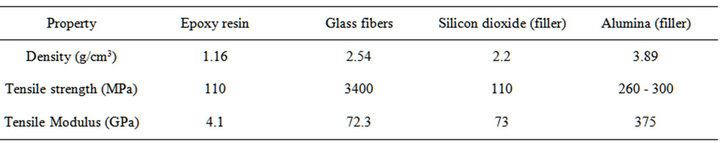
Table 2. Physico-mechanical properties of epoxy resin, glass fiber and fillers.
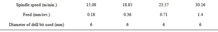
Table 3. Cutting conditions employed in the present study.
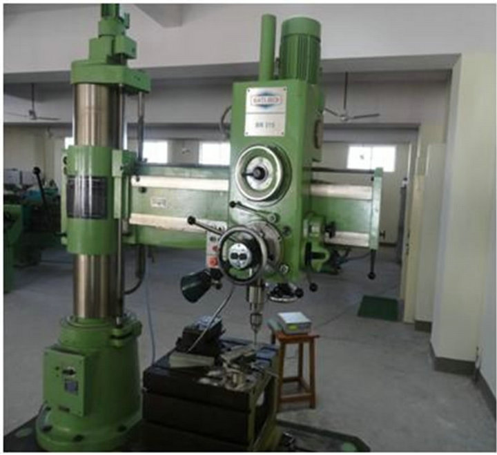
Figure 1. Drilling machine showing the dynamometer used for measurement of cutting forces.
using scanning electron microscope (SEM) and analyzed.
3. Results and Discussion
3.1 Evaluation of Physico-Mechanical Properties
The physico-mechanical properties such as density, hardness, tensile strength and tensile modulus data of unfilled and particulate filled G-E composites are given in Table 4. The results revealed that particulate filled GE composites showed better mechanical properties than that of unfilled G-E composites. Comparing the results it was observed that the inclusion of ceramic fillers into G-E showed higher density. The incorporation of SiO2 and Al2O3 filler in G-E composites increased the tensile strength. Elongation properties decreased with the presence of filler that indicates interference by the filler in the deformability of the matrix. Al2O3 filled G-E composites showed improved mechanical properties compared to unfilled and SiO2 filled G-E composites. It should be pointed out that the presence of SiO2 and Al2O3 fillers improved adhesion and it has been proved to be beneficial in glass fiber reinforced epoxy composites.
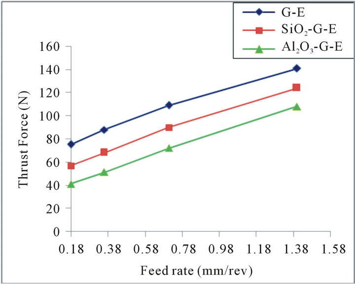
3.2. Effect of Cutting Speed and Feed on Thrust and Torque Using HSS Drill Bit
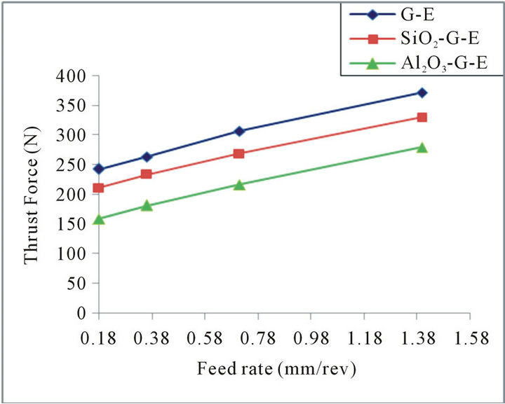
Figures 2(a) and (b), and Figures 3(a) and (b) show the parametric variation of thrust force and torque with feed rate for two cutting speeds of particulate filled G-E composites using HSS tool.
It can be observed that thrust force and torque generally increased with feed rate. This fact was due to the increasing the cross-sectional area of the undeformed chip.

Table 4. Physico-mechanical properties of G-E, SiO2 and Al2O3 filled G-E composites.
The presence of ceramic filler in composites increases the hardness and cutting resistance of the material, also may result in wears the cutting edges of the drill through drilling one hole. Therefore the thrust force and torque were increased with increasing cutting speed. The addition of filler reduces the thrust force for both 15.08 and 30.16 m/min cutting speeds. From Figures 1 and 2, it can be seen that alumina filled G-E composites showed the lower thrust and torque value for different cutting speeds as compared to the unfilled and SiO2 filled G-E composites.
3.3. Effect of Cutting Speed and Feed on Thrust and Torque Using Carbide Drill Bit
Figures 4(a) and (b), and Figures 5(a) and (b) show the influence of drilling variables on peak thrust force and torque, respectively, for unfilled and particulate filled composites. The results in these figures indicate that, the thrust force and torque were increased with increasing feed. This fact was due to the increasing the cross-sectional area of the undeformed chip. The presence of fillers with the abrasive nature in G-E composite that, in addition to increasing the hardness and cutting resistance of the material, also may result in wears the cutting edges of the drill through drilling one hole. Therefore the thrust force and torque were increased with increasing cutting speed (Figures 4 and 5).
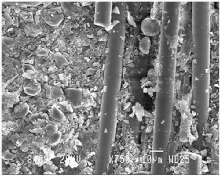
3.4. Drilled Surface Morphology for HSS Drill Bit
The SEM micrographs show the breakage of the fiber material and damage of the matrix material. Figure 6(a) shows the less breakage of fiber material and also ruptured matrix but as the speed and feed are increasing the breakage of fibers is more as seen and also more ploughing and fiber buckling of the fibers with adhesion of matrix debris on the fiber surface as shown in Figure 6(b).
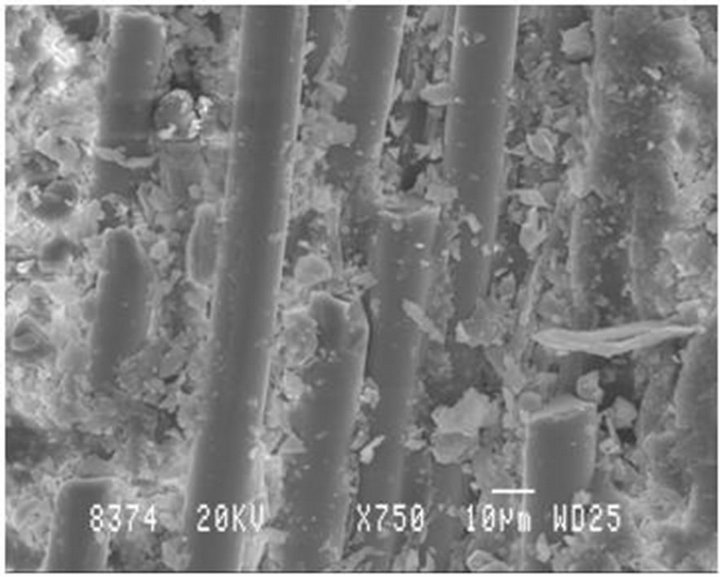
The SEM micrographs show the breakage of the fiber material and damage of the matrix material. Figure 7(a) shows the less breakage of fiber material and also damaged matrix but as the speed and feed are increased the breakage of fibers is more as seen in Figure 7(b) due to
 (a)
(a) (b)
(b)
Figure 2. Variation of thrust force with feed rate for filled & unfilled G-E composites using HSS drill bit at (a) 15.08 m/min and (b) 30.16 m/min.
 (a)
(a)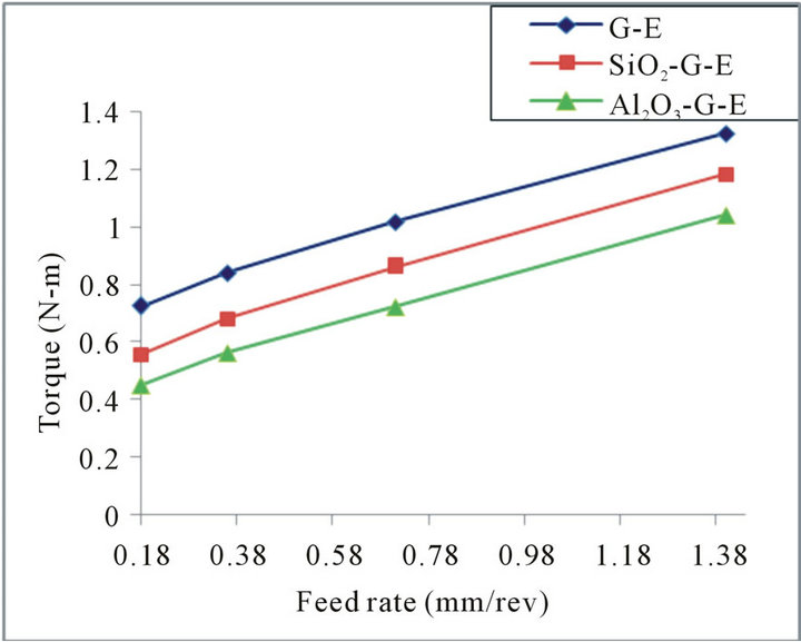 (b)
(b)
Figure 3. Variation of torque with feed rate for filled and unfilled G-E composites using HSS drill bit at (a) 15.08 m/min and (b) 30.16 m/min.
 (a)
(a)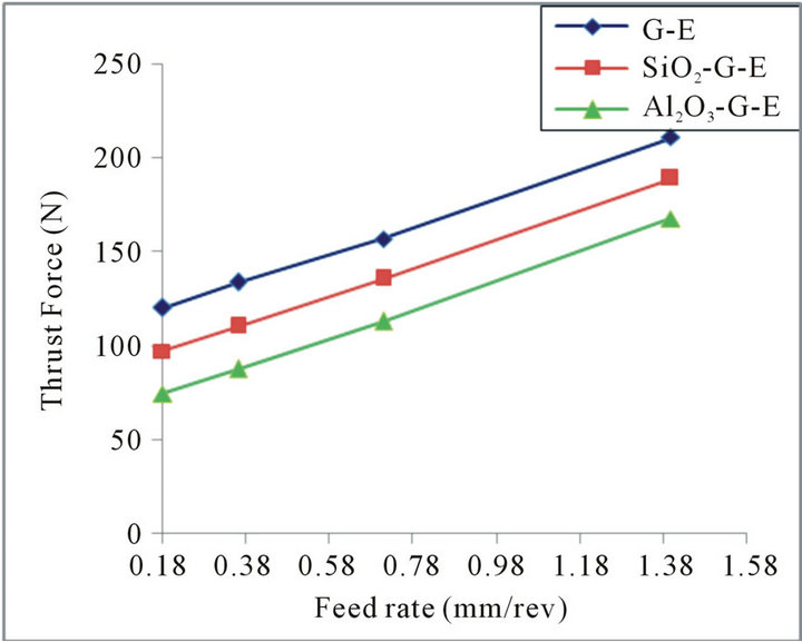 (b)
(b)
Figure 4. Variation of thrust force with feed rate for filled and unfilled G-E composites using carbide drill bit at (a) 15.08 m/min and (b) 30.16 m/min.
 (a)
(a)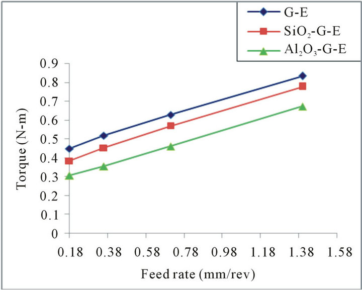 (b)
(b)
Figure 5. Variation of torque with feed rate for filled and unfilled G-E composites using carbide drill bit at (a) 15.08 m/min and (b) 30.16 m/min.
 (a)
(a) (b)
(b)
Figure 6. SEM Micrographs of the G-E using HSS drill bit at (a) 15.08 m/min, 0.18 mm/rev and (b) 30.16 m/min, 1.40 mm/rev.
 (a)
(a)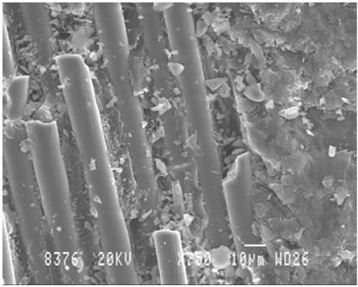 (b)
(b)
Figure 7. SEM Micrographs of the G-E with SiO2 using HSS drill bit at (a) 15.08 m/min, 0.18 mm/rev and (b) 30.16 m/min, 1.40 mm/rev.
delamination between the layers of the material. At higher cutting conditions (high speed and feed), the thrust force caused visible cracking of surface layer as seen in Figure 7(b) which resulted in deterioration of the surface, due to high speed and feed which includes fiber fragmentation, matrix debris, large number of fiber breakage, inclined fiber fracture, severe debonding at fiber matrix interface.
The SEM micrographs show the breakage of the fiber material and damage of the matrix material. Figure 8(a) shows the fibers are totally misaligned and the formation of voids in between the matrix and the fiber is clearly observed and the drilled surface at lower speed and feed seems to have less no of cracks resulting in lower value of surface roughness. In the Figure 8(b) it shows the breakage of fiber material and also the ploughing action of fibers due to the poor bonding between fibers and matrix, inclined fiber breakage and cohesive resin fracture.
3.5. Drilled Surface Morphology for Carbide Drill Bit
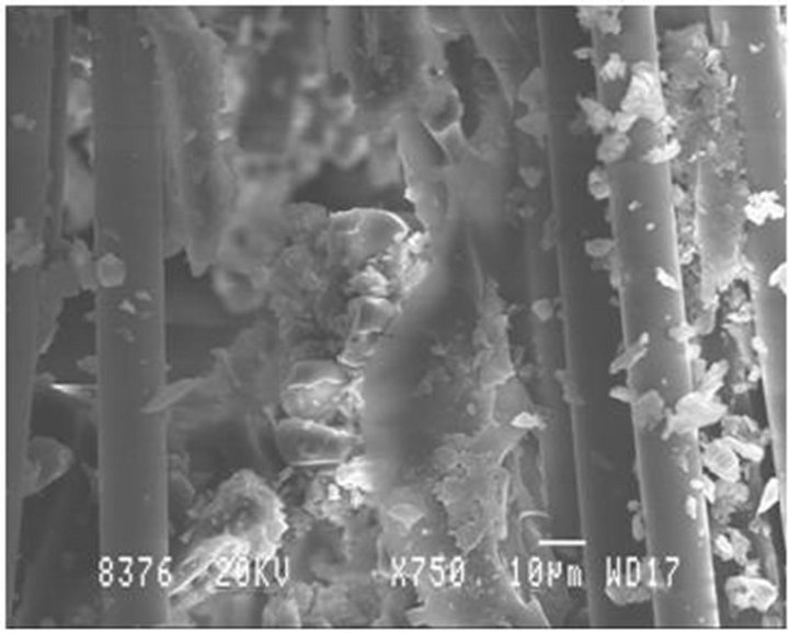
The SEM micrographs show the breakage of the fiber material and damage of the matrix material. Figure 9(a) shows that the longitudinal fibers are pulled up and are oriented and more breakage of matrix material such as cohesive bonding of matrix and fiber at interface, more transverse fiber breakage, matrix debris, voids and fiber fragmentation but as the speed and feed are increased the breakage of fibers as well as the matrix is increased and also chopping of fibers is being seen in Figure 9(b).
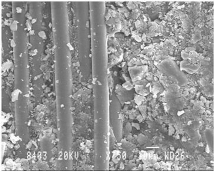
Figure 10(a) shows the less breakage of fiber material and more damage to the matrix material at lower speed
 (a)
(a)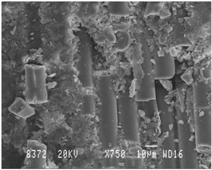 (b)
(b)
Figure 8. SEM micrographs of the G-E material with Al2O3 filler using HSS drill bit at (a) 15.08 m/min, 0.18 mm/rev and (b) 30.16 m/min, 1.40 mm/rev.
 (a)
(a)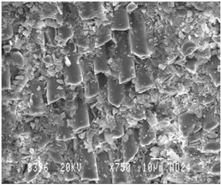 (b)
(b)
Figure 9. SEM micrographs of the G-E using carbide drill bit at (a) 15.08 m/min, 0.18 mm/rev and (b) 30.16 m/min, 1.40 mm/rev.
 (a)
(a) (b)
(b)
Figure 10. SEM micrographs of the G-E with SiO2 using carbide drill bit at (a) 15.08 m/min, 0.18 mm/rev and (b) 30.16 m/min, 1.40 mm/rev.
 (a)
(a)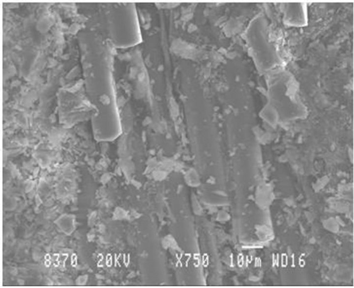 (b)
(b)
Figure 11. SEM Micrographs of the G-E with Al2O3 using Carbide drill bit at (a) 15.08 m/min, 0.18 mm/rev and (b) 30.16 m/min, 1.40 mm/rev.
and feed the drilled work surface showed the similar surface features such as cohesive bonding of matrix and fiber at interface, more transverse fiber breakage, matrix debris, voids and fiber fragmentation and as the speed and feed are increased the e breakage of fibers and matrix is more as seen in Figure 10(b).
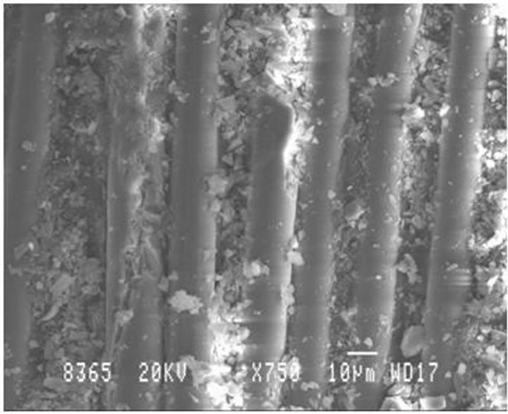
The SEM micrographs show the breakage of the fiber material and damage of the matrix material. Figure 11(a) shows the breakage of matrix material and also less damaged fibers but as the speed and feed are increasing the breakage of fibers as well as orientation of the fibers is seen with damaged matrix as seen in Figure 11(b).
4. Conclusions
From the experimental work, the drilling parameters, which are having influence on thrust and torque on the drilling of SiO2/Al2O3 filled G-E composites, have been assessed.
• Unfilled and particulate filled G-E composites results reveal that thrust and torque depends on speed and feed. Further it is seen that with the increase in speed and feed, thrust and torque values showed an increasing trend.
• Alumina particulate filled G-E composite showed optimal thrust and torque values as compared to unfilled G-E and SiO2 particulate filled G-E composites using carbide drill bit.
• SEM micrographs show that in drilling of G-E composites by carbide drill bit minimal material damage was observed. During drilling process the important SEM features observed were fiber fracture, cohesive resin fracture etc.
• From the experimental results carbide drill bit is the best tool for drilling of particulate filled G-E composites.
REFERENCES
- J. Mathew, N. Ramakrishnan and N. K. Naik, “Investigations into the Effect of Geometry of a Trepanning Tool on Thrust and Torque during Drilling of GFRP Composites,” Journal of Materials Processing Technology, Vol. 91, No. 1, 1999, pp. 1-11. doi:10.1016/S0924-0136(98)00416-6
- I. El-Sonbaty, U. A. Khashaba and T. Machaly, “Factors Affecting the Machinability of GFR/Epoxy Composites,” Composite Structures, Vol. 63, No. 3, 2004, pp. 329-338. doi:10.1016/S0263-8223(03)00181-8
- R. Zitoune, V. Krishnaraj and F. Collombet, “Study of Drilling of Composite Material and Aluminium Stack,” Composite Structures, Vol. 92, No. 5, 2008, pp. 1246- 1255.
- E. Capello and V. Tagliaferri, “Drilling Damage of GFRP and Residual Mechanical Behavior—Part I: Drilling Damage Generation,” Journal of Composites Technology and Research, Vol. 23, No. 2, 2001, pp. 122-130. doi:10.1520/CTR10920J
- S. Arul, L. Vijayaraghavan, S. K. Malhotra and R. Krishnamurthy, “The Effect of Vibratory Drilling on Hole Quality in Polymeric Composites,” International Journal of Machine Tools & Manufacture, Vol. 46, No. 3-4, 2006, pp. 252-259. doi:10.1016/j.ijmachtools.2005.05.023
- H. Hocheng and C. C. Tsao, “Analysis of Delamination in Drilling Composite Materials Using Core Drill,” Australian Journal of Mechanical Engineering, Vol. 1, No. 1, 2004, pp. 49-53.
- S. C. Lin and I. K. Chen, “Drilling Carbon Fiber-Reinforced Composite Material at High Speed,” Wear, Vol. 194, No. 1-2, 1999, pp. 156-162. doi:10.1016/0043-1648(95)06831-7
- U. A. Khashaba, “Delamination in Drilling GFR—Thermoset Composites,” Composite Structures, Vol. 63, No. 3-4, 2004, pp. 313-327. doi:10.1016/S0263-8223(03)00180-6
- R. Piquet, B. Ferret, F. Lachaud and P. Swider, “Experimental Analysis of Drilling Damage in Thin Carbon/Epoxy Plate Using Special Drills,” Composites Part A, Vol. 31, No. 10, 2000, pp. 1107-1115. doi:10.1016/S1359-835X(00)00069-5
- V. Krishnaraj, S. Vijayarangan and A. Ramesh Kumar, “Effect of Drilling Parameters on Mechanical Strength in Drilling Glass Fiber Reinforced Plastic,” International Journal of Computer Applications in Technology, Vol. 28, No. 1, 2007, pp. 87-93. doi:10.1504/IJCAT.2007.012336
- A. M. Abrao, P. E. Faria, J. C. Campos Rubio, P. Reis and J. Paulo Davim, “Drilling of Fiber Reinforced Plastics: A Review,” Journal of Materials Processing Technology, Vol. 186, No. 1-3, 2007, pp. 1-7. doi:10.1016/j.jmatprotec.2006.11.146
- C. C. Tsao and H. Hocheng, “Evaluation of Thrust Force and Surface Roughness in Drilling Composite Material using Taguchi Analysis and Neural Network,” Journal of Materials Processing Technology, Vol. 203, No. 1-3, 2008, pp. 342-348. doi:10.1016/j.jmatprotec.2006.04.126
- V. Krishnaraj, S. Vijayarangan and G. Suresh, “An Investigation on High Speed Drilling of Glass Fiber Reinforced Plastic (GFRP),” Indian Journal of Engineering & Materials Sciences, Vol. 12, No. 3, 2005, pp. 189-195.
- S. K. Malhotra, “Some Studies on Drilling of Fibrous Composites,” Journal of Materials Processing Technology, Vol. 24, 1990, pp. 291-300. doi:10.1016/0924-0136(90)90190-6
- J. Ramkumar, S. K. Malhotra and R. Krishnamurthy, “Studies on Drilling of Glass/Epoxy Laminates Using Coated High Speed Steel Drills,” Journal of Materials and Manufacturing Processes, Vol. 17, No. 2, 2002, pp. 213-222. doi:10.1081/AMP-120003531
NOTES
w*Corresponding author.