Modeling and Numerical Simulation of Material Science
Vol.3 No.1(2013), Article ID:26910,9 pages DOI:10.4236/mnsms.2013.31006
Theoretical and Numerical Comparison of Limit Point Bifurcation and Maximum Force Criteria. Application to the Prediction of Diffuse Necking
Université de Lyon, CNRS INSA-Lyon, Villeurbanne, France
Email: guillaume.altmeyer@gmail.com
Received October 27, 2012; revised November 29, 2012; accepted December 10, 2012
Keywords: Forming; Bifurcation Analysis; Maximum Force Criterion; Diffuse Necking; Forming Limit Diagram
ABSTRACT
A large number of criteria has been developed to predict material instabilities, but their choice is limited by the lack of existing comparison of their theoretical basis and application domains. To overcome this limitation, a theoretical and numerical comparison of two major models used to predict diffuse necking is present in this paper. Limit Point Bifurcation criterion is first introduced. An original formulation of the Maximum Force Criterion (MFC), taking into account the effects of damage and isotropic and kinematic hardenings, is then proposed. Strong connections are shown between them by comparing their theoretical basis. Numerical Forming Limit Diagrams at diffuse necking obtained with these criteria for different metallic materials are given. They illustrate the theoretical link and similar predictions are shown for both models.
1. Introduction
Environmental constraints lead major mechanical Industries to reduce the weight of the structures. This objective can be achieved by using new materials and advanced dimensioning methods, but new unexpected diffuse and localized necking modes may then occur during sheet metal forming operations. Prediction of material instability becomes a major industrial challenge. Forming Limit Diagrams (FLD) can be determined by costly experimental means [1,2] or by numerical simulation. A review of four theoretical principle commonly used to predict the occurrence of necking lighten their ability to take into account the physics of necking or their limits to be coupled with advanced material modeling [3].
A first approach to determine the formability limits is based on the existence of multiple heterogeneous areas in the sheet [4-6]. According to Marciniak-Kuczynski [4], a band of reduced thickness in which necking is expected is arbitrarily introduced in a safe media. The comparison of the evolution of the mechanical properties inside and outside the defect area allows the prediction of localization. M-K model is applicable to a wide range of materials. Limitations of this criterion come from the requirement of user defined parameters, as for example the initial defect size or the threshold value. Another analytical method, the Maximum Force Principle, is based on an empirical observation according to which diffuse necking occurs when the load reaches its maximum during a uniaxial tensile test [7]. Extensions to this criterion have been proposed to predict diffuse necking [8] and latter localized necking [9-15] of metal sheets submitted to biaxial loadings. Although some interesting trends are found by comparing experimental and numerical results obtained with these criteria [16], their theoretical foundations still have to be reinforced or revisited to take into account more advanced material modeling. To overcome these limitations, bifurcation analysis criteria can be investigated. According to this approach, a necessary condition for diffuse necking is given by the loss of positiveity of the second order work [17,18]. For localized modes, the loss of ellipticity criterion was established to predict necking or shear banding [19-21]. This criterion is however restricted to both rate independent materials and softening behavior. The first restriction can lead to unrealistic and too restrictive formability predictions for rate dependant materials. In such case, stability analysis by a linear perturbation method may be used to improve the forming limit diagram predictions. Necking and localization are seen as instability of the global or local mechanical equilibrium [22-25].
To choose the most adapted criterion for a specific application, one has to be conscious of the advantages, the limits of each criterion and the relations that exist between criteria based on different approaches. The first aim of this paper is to compare the bases of diffuse necking criteria based on bifurcation analysis and on the maximum force principle to show theoretical and numerical links between them. The second one is to propose a development of MFC to take into account effects of damage and different isotropic and kinematic hardenings.
After a presentation of the General Bifurcation and Limit Point Bifurcation criteria an extension of the Maximum Force Criterion to damage and different strain hardenings is proposed. Some theoretical investigations on the connections that could exist between them are lead and then illustrated in a last part by numerical simulation of FLD.
2. Diffuse Necking Criteria
2.1. General Bifurcation Criterion
Following this approach, diffuse necking is seen as the change from a quasi-homogeneous mechanical state to a heterogeneous one. General Bifurcation Criterion (GBC) has been introduced by Drucker [17] and then Hill [18] as a sufficient condition for uniqueness of the solution of the equilibrium problem for time independent materials. Let consider two different stress fields ΠA and ΠB associated with two kinematically admissible velocity fields VA and VB respectively. Application of virtual power principle leads to:
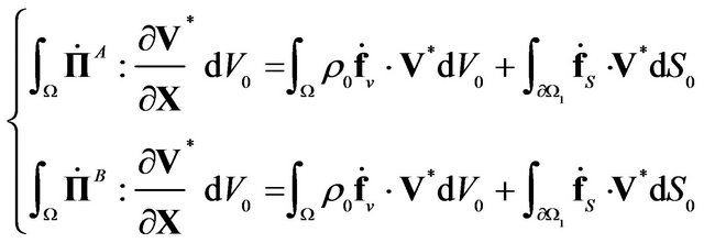
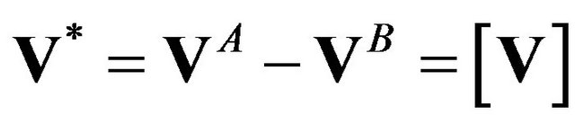
where Π denotes the first Piola-Kirchhoff stress tensor and fv and fs the body force per unit volume and the traction applied on the solid. This set of equations is particularly verified for the virtual field:
 .
.
The condition for loss of uniqueness may then be obtained from writing the difference between the previous equations for this particular choice of virtual velocity field:
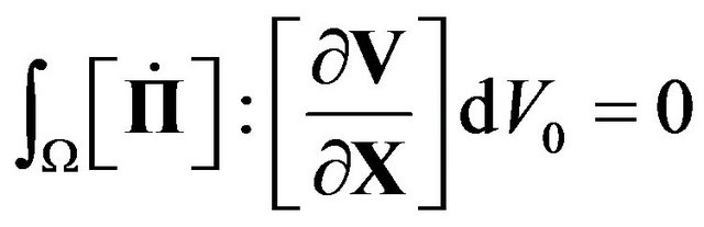
It is shown that this functional is always superior to Hill’s functional in the case of rigid-plastic or elasticplastic materials [18]. Sufficient condition for uniqueness is then related to positivity of Hill’s functional. This expression of GBC depends on boundary conditions and can be considered as a structural or geometric criterion. For material bifurcation studies, the criterion is applied on a local level, under the following more restrictive form:
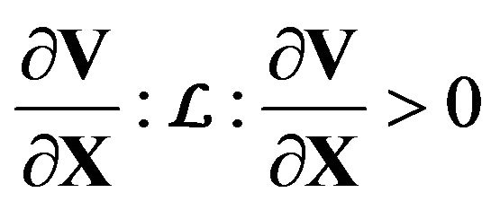
A sufficient condition for uniqueness of the solution of the boundary problem is the positive-definiteness of the quadratic form , that can also be seen as the singularity of the symmetric part of tangent modulus L relating the first Piola-Kirchhoff tensor and the velocity gradient. One has then to verify that all eigenvalues of the symmetric part of this tensor remain positive. GBC can be seen as a lower bound for diffuse necking exclusion.
2.2. Limit Point Bifurcation
As a particular case of general bifurcation, diffuse necking is associated with a stationary state of the nominal stress [26,27]:
Combining this condition with material behavior equations, one may obtain:
Limit Point Bifurcation (LPB) is associated with the singularity of the tangent modulus and is reached for the first nil eigenvalue of the tangent modulus L.
2.3. Maximum Force Criterion
Necking criteria derived from the Maximum Force principle are based on experimental observations according to which plastic instability occurs when the force reaches its maximum during a tensile test [7]. This onedimensional criterion has later been extended to bi-dimensional loadings by Swift for the prediction of diffuse necking in metal sheets, leading to the formulation of the Maximum Force Criterion (MFC) [8]. According to Swift’s hypothesis, necking is related to the maximum of both major and minor applied forces. It can be expressed as:
where indices 1 and 2 denote respectively the major and minor directions of the applied load F. It can be noticed that the third component of the load is null under the chosen hypothesis of bi-axial loading. It has been shown that elasticity plays a negligible role [28] and will then not be considered in the following developments, without any loss of generality.
2.3.1. Swift Classical Formulation
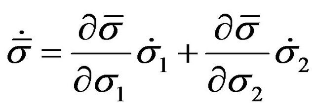
In this section, Swift Maximum Force criterion is derived under the most commonly used hypothesis. From Equation , a relation can be established between stress and strain rate components, for example [29]:
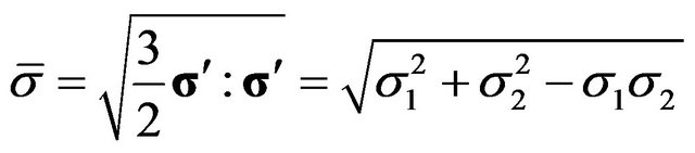
Derivation of the equivalent stress leads to:
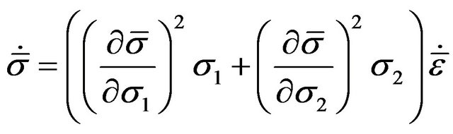
By combining relations and and by using the plastic flow law, a relation between equivalent stress and strain rates is obtained:
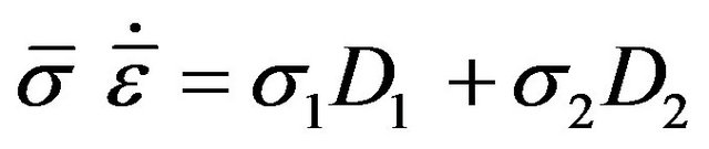
On another hand, plastic work is defined as:
Swift necking condition is obtained by computing the ratio of Equations and :
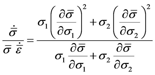
This general formulation of MFC can be developed for different class of materials. In the following sub-sections, an expression of Swift criterion is obtained for a simplified rigid-plastic modeling as well as for more advanced plastic behaviors, including the effects of kinematic hardening and damage.
2.3.2. Simplified Rigid-Plastic Case
Analytical expression of MFC may be obtained for a simplified rigid-plastic material modeling based on Hollomon isotropic hardening law and von Mises isotropic yield surface, which can be written as [29]:
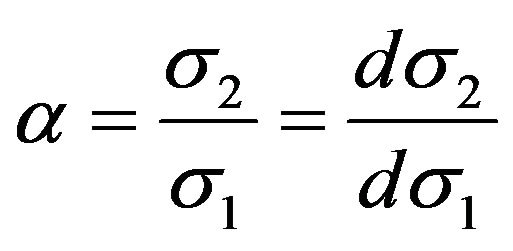
For proportional loadings, Cauchy stress ratio α is constant and verifies:
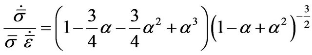
On one hand, partial derivatives of von Mises equivalent stress and then MFC may be expressed as functions of this ratio, such that after calculations:
One the other hand, a relation between the yield stress and the equivalent plastic strain is derived from Hollomon isotropic hardening law during plastic loading. This relation is written as:
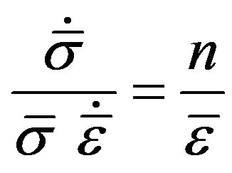
where n is the exponent of Hollomon law. From Equations and , the critical equivalent strain at the initiation of necking can be written under the following analytical expression:
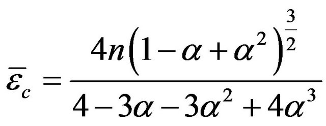
and then the major and minor critical strains may be deduced from this relation and the expression of the plastic flow law:
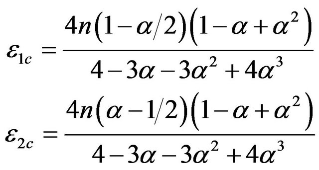
Forming Limit Diagrams (FLD) may be plotted from Equation and illustrations of this simplified case are given in the last section of the paper. It is worth noting that the major critical strain obtained with MFC equals the hardening coefficient n for uniaxial tension, for plane tension and for equibiaxial expansion. With new materials, this formulation is no more sufficient to predict accurately necking and the criterion has to be enhanced to take into account the effects of advanced modeling. This development is proposed in the following section.
2.3.3. Coupling of Different Isotropic Hardening, Kinematic Hardening or Damage Laws with MFC
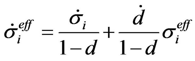
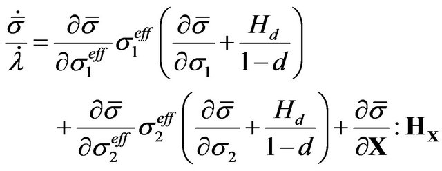
After the formulation of MFC in the case of a simplified rigid-plastic modeling, it is proposed in this section to rewrite the necking criterion to take into account the effects of induced anisotropy or of softening by coupling the criterion with kinematic hardening and ductile damage. The same approach as in the simplified case is followed. Equations and remain valid, but additional terms appear in the expression of the equivalent stress rate:
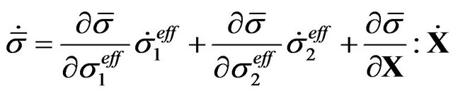
where σieff denotes a principal component of the effective stress tensor and X the kinematic hardening tensor. Time derivative of the effective stress reads:
At necking initiation, material behavior and Swift’s condition lead to:
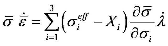
Furthermore, plastic equivalent work expression becomes after coupling with damage and kinematic hardening:
From the ratio of Equations and , a new expression of MFC is obtained:
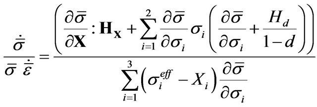
This expression of the MFC allows the prediction of necking for a larger class of elastic-plastic materials. One can verify that in absence of damage and kinematic hardening, Equation becomes equivalent to Equation corresponding to the uncoupled model. FLD obtained with this formulation will be compared with those plotted with GBC and LPB in the last section of this paper.
2.4. Theoretical Relation between GBC, LPB and MFC
Bifurcation analysis criteria and MFC are based respecttively on strong theoretical considerations and on an empirical observation. They may seem really different, but some relations between them are investigated in this section. Summarizing previous hypotheses presented during the formulation of MFC, this criterion is based on the stationariness of the applied loads at the initiation of diffuse necking, on in plane loading and additionally on loading in the direction of the anisotropy axes, then at necking initiation:
or in term of nominal stresses N:
When these conditions are verified in a solid, General Bifurcation condition is always verified. MFC can be seen as a sufficient condition for general bifurcation and GBC is more conservative than MFC. Furthermore, introducing the relation between nominal stress tensor and velocity gradient, one can write:
For non trivial solution, MFC is then related to the singularity of the tangent modulus L, a condition that is equivalent to the LPB condition when Swift’s conditions are applied. LPB can be interpreted as a generalization of MFC to three dimensional and non proportional loads for elastic-plastic materials. The hypotheses of neglecting elasticity effects and in plane linear loading in the direction of anisotropy axes are not necessary. They seem being used only to simplify analytical formulation of the necking criterion. Swift’s hypotheses may be revised. Swift maximum loads hypothesis has mainly be criticized because it is verified only for a very restrictive set of loading paths [30]. The comparison between the theoretical bases of LPB and MFC offers a new interpretation of this criterion, diffuse necking being related to the loss of uniqueness of the solution of the equilibrium problem. MFC can be seen as a particular case of LPB for plane stress loading.
3. Application to Form Limit Diagrams
3.1. Constitutive Modeling
During deep-drawing operations, metallic sheets are subjected to large transformations. A large number of modeling has been developed to characterize elastoplastic behaviors, based on physical observations or on phenomenological approaches. For simplicity reasons, a phenomenological modeling is considered here, allowing representing the effects of elasticity, initial and induced anisotropy, hardening and softening [31,32]. Use of more advanced models could improve the accuracy of the predicted formability limits, but they are not considered here as the aim of this paper is the comparison of theoretical basis of diffuse necking criteria. This modeling is based on a hypo-elastic law:
where C is the elastic modulus, relating the rate of the Cauchy stress tensor σ to the elastic strain rate tensor De defined as the difference between the total strain rate D and the plastic strain rate Dp. This tensor can be computed from the associated plastic flow law:
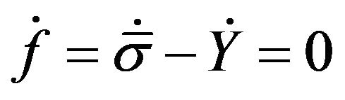
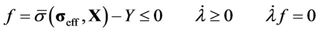
with  the plastic multiplier and f a potential that can be written under the Kuhn-Tucker form:
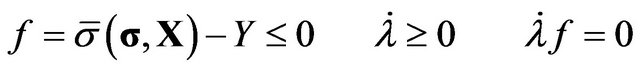
where , Y and X denote respectively the equivalent stress, the size of the loading surface and kinematic hardening variable. In the applications proposed in the last part of this paper, von Mises isotropic and Hill’s 48 anisotropic functions are used to write the equivalent stress. Hill’s 48 function is defined with a combination of Lankford’s coefficients r0, r45 and r90. More details about their formulations are present in [3]. The chosen evolution of the kinematic hardening is represented by Armstrong-Frederick non linear law:
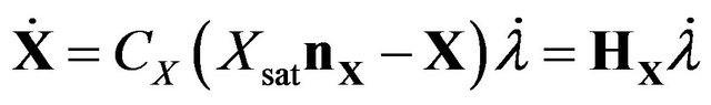
The material constants CX and Xsat are related to the saturation rate and the saturation value of the kinematic hardening and nX the saturation direction defined as:
The current size of the loading surface is related to the initial size of the elastic domain Y0 and to the isotropic variable R:
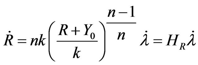
Different laws may be used to describe the evolution of the isotropic hardening variable. A first law is adapted to materials exhibiting a saturating evolution of hardening:
with CR and Rsat two material parameters used to represent the saturation rate and the saturation value of the isotropic hardening variable. Without damage coupling, the plastic multiplier is equal to the equivalent strain rate. For non saturating materials, Swift power law is more adapted and is commonly used:
Equation can be rewritten as:
where Y0 is the initial size of the elastic area and can be defined as a function of the three material parameters n, k and ε0:
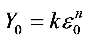 .
.
This law is equivalent to Hollomon power law when ε0 is nil. On another way, consistency condition is defined as:
Combining the previous equations, one can write the expression of the plastic multiplier and then establish the relation between the stress and strain tensors:
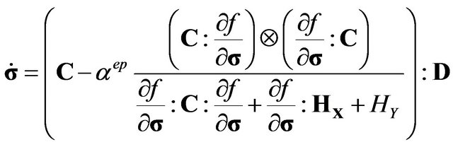
or:

where L is the tangent modulus and αep a plastic load indicator that is nil during elastic loading or unloading or equals to the unity during plastic loading. This method is applicable to a wide range of material modeling and can be used to introduce other behavior, as for example softening.
Different approaches have been developed these last decades to represent the effects of damage. In the continuous damage mechanic framework, damage is related to the surface density of micro-defects present in an elementary volume element. Following Lemaitre’s approach [33], damage variable is defined as the ratio between the surface of the micro-defects and the total surface of the elementary volume. The effective stress is related to the usual stress by:
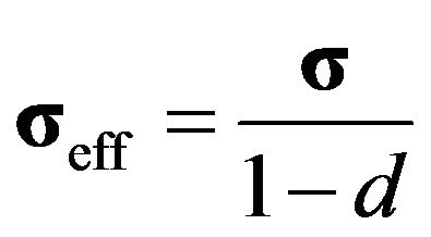
where d represents the isotropic damage variable. The evolution of this variable is given by:
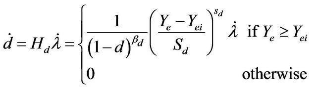
with Sd, sd and βd three materials parameters, Ye the elastic energy release rate and Yei an activation threshold. Adopting the strain equivalence principle, strain rate and Cauchy stress rate are related by the following incremental law:
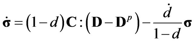
where Dp is defined in the associative flow rule . After coupling with damage, the loading surface becomes:
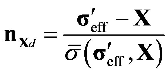
The evolution law of isotropic hardening remains valid, but the normal to the saturation direction of the kinematic hardening is affected and becomes:
Combining these new relations in the same way as in the case of uncoupled model, one can obtain the relation between the Cauchy stress rate and the strain rate tensors:
where L is the coupled tangent operator defined as:
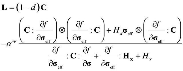
When damage is nil, Equations and defining this tensor become equivalent. A detailed development of these models is given in [31].
3.2. Numerical FLD
Some theoretical links have been enlightened between MFC, LPB and GBC in the second part. Numerical FLD obtained are now proposed for different materials and material behaviors to illustrate these relations.
First isotropic hardening is modeled with a Swift exponential law on an Aluminium alloy [34]. Data corresponding to this application are given in Table 1.
From this set of material parameters, FLD are computed with an internal code for MFC, LPB and GBC criteria and plotted in Figure 1.
For these examples, material behavior is modeled in the framework of associated plasticity and the load is
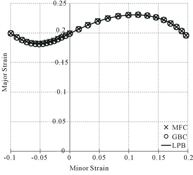
Figure 1. FLD of an aluminium alloy.
Table 1. Materials parameters for an aluminium alloy.
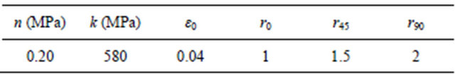
applied in the anisotropy directions. Under these conditions, tangent modulus remains symmetric. As the first annulations of an eigenvalue of the tangent modulus and respectively its symmetric part are investigated with LPB and GBC, both criteria lead exactly to the same predicttion. This observation has been verified for the different forming limit diagrams presented in this section. The prediction obtained with GBC will not be represented in the next Figures for readability reasons. When a Hollomon power law is used, a theoretical result states that the critical minor strain is equal to the hardening exponent n for uniaxial tension, for plane tension and for equibiaxial expansion. One may verify that this theoretical result is well verified by the numerical simulation. Anisotropy and ε0 parameter are neglected in the theory, their use in the simulation may explain the small differences between theoretical and numerical results obtained in Figure 1. The same critical deformations at diffuse necking are predicted with the three criteria, the small relative differences (less than 1%) may come from numerical approximations.
A second simulation is lead for a Dual-Phase steel sheet exhibiting a saturation of isotropic hardening. Saturating law is then used to model the behavior of this alloy and material parameters are the following:
First observation is that the choice of the hardening law has a great impact on the shape of the curve. The classical “S shape” obtained with Hollomon and Swift exponential laws is no more observed in Figure 2 with saturating law.
The second observation is the really good accordance of the FLD obtained with MFC and LPB, which verifies the theoretical link mentioned in Section 2.4.
A first aim of this paper was to show the link existing between three major diffuse necking criteria. The second contribution of this paper is to propose a version of MFC that take into account the effects of kinematic hardening and damage. Two applications are proposed to illustrate their influence on FLD: one using kinematic hardening and the other coupling damage and isotropic hardening. Different steels are considered. New material parameters sets are summarized in Tables 3 and 4.
It is worth noting the similarity between the values of hardening parameters presented in Table 2 and in Table 3, leading to the same saturation limit, but physical meaning of the variables used in these applications remain really different. The corresponding FLD is given in Figure 3.
Similar results are still obtained with MFC and LPB. Use of kinematical hardening or to a combination of isotropic and kinematic hardenings may be chosen to improve numerical simulations in case of non linear or non direct applied strain path. These kind of loading path are frequently encountered during deep-drawing of real structures. This coupling is now available with the proposed formulation of MFC.
Due to the simplicity of the classical formulation of MFC, CPU time consumption is lower with this criterion than with LPB. This advantage tends however to be reduced with the coupled version of the MFC.
In this last application, damage is taken into account in the formability predictions. In this case, the coupled formulation of MFC is used during the simulation. The damage law evolution is based on an improvement of Lemaitre’s model and the parameters are presented in Table 4.
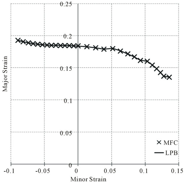
Figure 2. FLD of a dual-phase steel: isotropic hardening case.
Table 2. Hardening parameters for a Dual-Phase steel: isotropic hardening case [32].
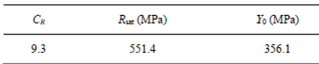
Table 3. Hardening parameters for a steel: kinematic hardening case.

Table 4. Hardening and damage parameters for a mild steel [32].
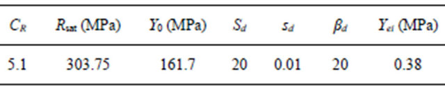
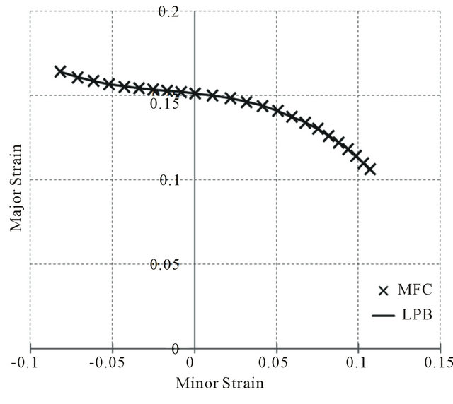
Figure 3. FLD of a steel: kinematic hardening case.
Associated FLD at diffuse necking obtained with LPB and MFC are given in Figure 4.
It is worth noting that once again the results obtained with MFC or LPB are exactly the same, which is in accordance with the theory. This statement could constitute an element toward the validation of the proposed coupling between damage and MFC. Damage tends to reduce the formability, as it can be seen by comparing the curves with and without damage. The choice of these parameters enlightens the phenomenon. The identification in [32] corresponds to an early bifurcation level. They may be too conservative and lead to an exaggerated effect of damage on diffuse necking initiation. This set of material parameters is however chosen here to enlighten the influence of damage on formability.
4. Conclusions
In summary, different diffuse necking criteria can be used to predict formability limits, including the Maximum Force Criterion based on an empirical observation and General Bifurcation Criterion and Limit Point Bifurcation based on bifurcation analysis.
1) Theoretical basis of these criteria are developed in a common framework, enabling a comparison of their theoretical bases. It is shown that GBC is a necessary condition for LPB and MFC. On another hand, MFC can be seen as a particular writing of LPB in the case of plane stress conditions or LPB can be interpreted as a generalization of MFC.
2) Classical formulation of MFC is restricted to simplified material modeling and loading conditions. To overcome these limitations, another formulation of the criterion is proposed. Isotropic and kinematic hardenings are introduced as well as isotropic damage.
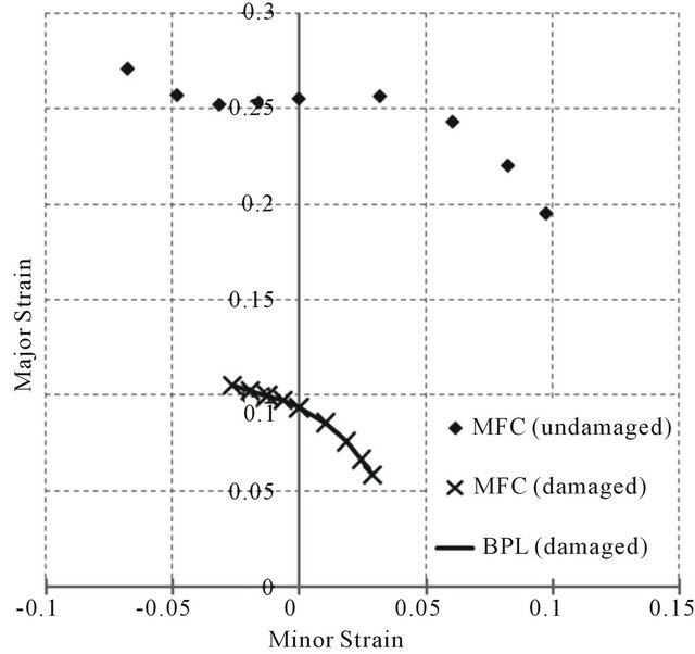
Figure 4. FLD of a mild steel: coupling with damage.
3) Numerical FLD are obtained to illustrate previous theoretical considerations. When large deformation framework is used, results obtained with GBC, LPB and MFC coincide with very good accuracy for different material modeling, including isotropic or kinematic hardenings and isotropic damage effects.
5. Acknowledgements
The author thanks Pr. F. Abed-Meraim and Dr. T. Balan (LEM3, Arts et Métiers ParisTech) for their help in deriving the theoretical bases of necking criteria and Arts et Métiers ParisTech for financial support.
REFERENCES
- S. P. Keeler and W. G. Brazier, “Relationship between Laboratory Material Characterization and Press-Shop Formability,” Microalloying, Vol. 75, 1975, pp. 517-530.
- K. Nakazima, T. Kikuma and K. Hasuka “Study on the Formability of Steel Sheets,” Yamata Technical Report, No. 264, 1968, pp. 8517-8530.
- G. Altmeyer, “Theoretical and Numerical Modeling of Plastic Instability Criteria. Application to the Prediction of Necking and Localization Phenomena,” Ph.D. Thesis, Arts et Métiers ParisTech, Metz, 2011.
- Z. Marciniak and K. Kuczyński, “Limit Strains in the Processes of Stretch-Forming Sheet Metal,” International Journal of Mechanical Sciences, Vol. 9, No. 9, 1967, pp. 613-620. doi:10.1016/0020-7403(67)90066-5
- A. Reyes, O. S. Hopperstad, T. Berstad and O. G. Lademo, “Prediction of Necking for Two Aluminium Alloys under Non-Proportional Loading by Using an FEBased Approach,” International Journal of Material Forming, Vol. 1, No. 4, 2008, pp. 211-232. doi:10.1007/s12289-008-0384-6
- P. Eyckens, A. V. Bael and P. V. Houtte, “MarciniakKuczynski Type Modelling of the Effect of ThroughThickness Shear on the Forming Limits of Sheet Metal,” International Journal of Plasticity, Vol. 25, No. 12, 2009, pp. 2249-2268. doi:10.1016/j.ijplas.2009.02.002
- A. Considère, “Report on the Use of Iron and Steel in Constructions,” Annals of Ponts and Chaussées, Vol. 9, 1885, p. 574.
- H. W. Swift, “Plastic Instability under Plane Stress,” Journal of the Mechanics and Physics of Solids, Vol. 1, No. 1, 1952, pp. 1-18. doi:10.1016/0022-5096(52)90002-1
- R. Hill, “On Discontinuous Plastic States, with Special Reference to Localized Necking in Thin Sheets,” Journal of the Mechanics and Physics of Solids, Vol. 1, No. 1, 1952, pp. 19-30. doi:10.1016/0022-5096(52)90003-3
- P. Hora, L. Tong and J. Reissner, “A Prediction Method of Ductile Sheet Metal Failure in FE Simulation,” Proceedings of Numisheet 1996, Zaragoza, 1996, pp. 252- 256.
- M. Brunet and F. Morestin, “Experimental and Analytical Necking Studies of Anisotropic Sheet Metals,” Journal of Materials Processing Technology, Vol. 112, No. 2-3, 2001, pp. 214-226. doi:10.1016/S0924-0136(01)00578-7
- R. Hill, “On the Mechanics of Localized Necking in Anisotropic Sheet Metals,” Journal of the Mechanics and Physics of Solids, Vol. 49, No. 9, 2001, pp. 2055-2070. doi:10.1016/S0022-5096(01)00031-X
- P. Hora and L. Tong, “Numerical Prediction of FLC Using the Enhanced Modified Maximum Force Criterion (EMMFC),” Proceedings of FLC Zurich 2006, 2006, pp. 31-36.
- K. Mattiasson, M. Sigvant and M. Larson, “Methods for Forming Limit Prediction in Ductile Metal Sheets,” Proceedings of IDDRG 2006, Porto, 2006, pp. 1-9.
- H. Aretz, “Numerical Analysis of Diffuse and Localized Necking in Orthotropic Sheet Metals,” International Journal of Plasticity, Vol. 23, No. 5, 2007, pp. 798-840. doi:10.1016/j.ijplas.2006.07.005
- D. Banabic, S. Comsa, P. Jurco, S. Wagner, S. He and P. Van Houtte, “Prediction of Forming Limit Curves from Two Anisotropic Constitutive Models,” In: D. Banabic, Ed., Formability of Metallic Materials, Springer, Berlin, 2000.
- D. C. Drucker, “Some Implications of Work Hardening and Ideal Plasticity,” Quarterly of Applied Mathmatics, Vol. 7, 1950, pp. 411-418.
- R. Hill, “A General Theory of Uniqueness and Stability in Elastic-Plastic Solids,” Journal of the Mechanics and Physics of Solids, Vol. 6, No. 3, 1958, pp. 236-249. doi:10.1016/0022-5096(58)90029-2
- J. R. Rice, “The Localization of Plastic Deformation,” Proceedings of the 14th IUTAM Congress, Delft, 1976, pp. 207-220.
- J. W. Rudnicki and J. R. Rice, “Conditions for the Localization of Deformation in Pressure-Sensitive Dilatant Materials,” Journal of the Mechanics and Physics of Solids, Vol. 23, No. 6, 1975, pp. 371-394. doi:10.1016/0022-5096(75)90001-0
- S. Stören and J. R. Rice, “Localized Necking in Thin Sheets,” Journal of the Mechanics and Physics of Solids, Vol. 23, No. 6, 1975, pp. 421-441. doi:10.1016/0022-5096(75)90004-6
- A. Molinari and R. J. Clifton, “Viscoplastic Strain Localization in Simple Shear Mode: Exact Results in Non-Linear Theory,” CRAS Série II, Vol. 296, 1983, pp. 1-4.
- G. Barbier, A. Benallal and V. Cano, “Theoretical Relation between Linear Perturbation Method and Bifurcation Analysis Method for Strain Localization Prediction,” CRAS-Series IIB-Mechanics-Physics-Chemistry-Astronomy, Vol. 326, No. 3, 1998, pp. 153-158.
- A. Benallal, “Perturbation and Stability of Rate-Dependent Solids,” European Journal of Mechanics-A/Solids, Vol. 19, 2000, pp. 45-60.
- A. Lejeune, N. Boudeau, and J. C. Gelin, “Influence of Material and Process Parameters on Bursting During Hydroforming Process,” Journal of Materials Processing Technology, Vol. 143-144, No. 1, 2003, pp. 11-17. doi:10.1016/S0924-0136(03)00295-4
- K. C. Valanis, “Banding and Stability in Plastic Materials,” Acta Mechanica, Vol. 79, No. 1-2, 1989, pp. 113-141. doi:10.1007/BF01181483
- M. K. Neilsen and H. L. Schreyer, “Bifurcations in Elastic-Plastic Materials,” International Journal of Solids and Structures, Vol. 30, No. 4, 1993, pp. 521-544. doi:10.1016/0020-7683(93)90185-A
- M. Habbad, “Plastic Instabilities in Anisotropic ElastoPlasticity and Large Transformations,” Ph.D. Thesis, Centrale Lyon, Lyon, 1994.
- M. Ben Tahar, “Contribution to Study and Simulation of Hydroforming Process,” Ph.D. Thesis, ENSMP, Nice, 2005.
- S. Boumaiza, “Instabilities Prediction during Tubes Hydroforming,” Ph.D. Thesis, Insa-Lyon, Lyon, 2005.
- J. Lemaitre and J. L. Chaboche, “Mechanics of Solid Materials,” Cambridge University, Cambridge, 1990.
- B. Haddag, “Contribution to Sheet Metal Forming: Application to Springback and Localization,” Ph.D. Thesis, Arts et Métiers ParisTech, Metz, 2007.
- J. Lemaitre, “Continuous Damage Mechanics Model for Ductile Fracture,” Journal of Engineering Materials and Technology, Transactions of the ASME, Vol. 107, No. 1, 1985, pp. 83-89. doi:10.1115/1.3225775
- G. Altmeyer, F. Abed-Meraim and T. Balan, “Comparison of Forming Limit Diagrams Predicted with Different Localization Criteria,” Steel Research International, Vol. 79, No. 1, 2008, pp. 24-31.