Geomaterials
Vol. 2 No. 4 (2012) , Article ID: 24023 , 4 pages DOI:10.4236/gm.2012.24015
Distinct Element Modelling of Mahabaleshwar Road Cut Hill Slope
Department of Earth Sciences, Indian Institute of Technology Bombay, Mumbai, India
Email: *ashuddn@live.com
Received August 8, 2012; revised September 26, 2012; accepted October 11, 2012
Keywords: Distinct Element Method; UDEC; Slope Stability; Mahabaleshwar
ABSTRACT
Reliable estimates of slope stability are essential for safe design and planning of road cut hill slopes which accommodate a number of tourist destinations around the world. The failure of cut slopes along these hills puts human life in grave danger and it is also disastrous for the economy. In the present study, a section of 100 m high jointed basalt hill slope has been analyzed numerically in a distinct element code, which is apt for simulating the behavior for jointed rock. The analysis was carried out for both the dry and saturated conditions. The distinct element analysis of the hill slope demonstrates it to be marginally stable under dry condition, while for the saturated condition, the hill slope fails along well defined joint planes.
1. Introduction
Slope failures along road cut hill slopes are a perpetual sources of distress for city planners and human habitants. The failure along these cut slopes is devastating, resulting in enormous monetary loss as well as puts human life in danger. Failure of geological materials is intricate due to heterogeneity of the geo-material and other site-specific conditions. The stability of these slopes mainly depends on the rock strength, orientation and characteristic of the discontinuities and weathering conditions [1]. The joint characteristics and shear strength are the major factors dictating the stability of rock slopes [2,3]. The reduction in shear strength due to presence of joints can be detrimental for the overall health of the slope.
A study to ascertain the stability and probable failure mechanism is required to avert any failure in future [4,5]. Numerous tools are available to assess the stability of slopes viz. limit equilibrium analysis, finite element analysis, finite difference analysis and distinct element method [6,7]. Due to the presence of discontinuities, continuum models are not enough to simulate the jointed rock mass slopes. Distinct element models (DEM) are the most appropriate tools for the simulation of jointed and complex rock mass [2,3,8,9]. The joint attributes are crucial and critical for the stability of any rock slopes [10,11].
Cundall developed a DEM code, Universal Distinct Element Code (UDEC) to model the blocky rock systems [12,13]. UDEC divides the rock mass into discrete blocks. A discontinuity is represented in the model as a contact between the two blocks. The contact between each block is considered soft-contacts to solve the relative normal displacements at the block contacts [14]. The calculations are performed alternatively between applications of a force-displacement law at all contacts and Newton’s force law at all blocks in the distinct element method [15].
The DEM has been used previously by a number of researchers to simulate various rock engineering conditions. Zhang et al., have studied the dynamic behavior of a 120-m high rock slope using the DEM [16]. Esaki et al. modeled a natural slope to detect the instabilities caused by an excavation at the slope toe [17]. Bhasin and Kaynia and Kveldsvik et al., have explained the static and dynamic loading conditions in UDEC for high rock slopes [1,18]. Lin et al. conducted the dynamic analysis of rock slope based on practical seismic load and performed collapse analysis of the crack development in a rock slope [2]. Rathod et al. have used UDEC for the analysis of static and dynamic response of dam abutments with a liner Coulomb slip constitutive model [19].
The present study is concerned with the stability of a heterogeneous basalt hill slopes from Mahabaleshwar, India. A 100 m high section has been chosen which is traversed by two road cuts. The study has been conducted for both dry and wet conditions. The hill is composed of massive basalt which is interlayered with red bole layers. The joint pattern in basalts is usually random and erratic. Two prominent joint sets have been taken into consideration for the study based on extensive field investigations and data records. Exhaustive field study and laboratory experiment were carried out to extract the input parameters for the numerical simulation. The hill slope was numerically simulated in a distinct element code for its factor of safety and deformational characters under dry and saturated conditions.
2. Study Area
The study area forms a part of the Deccan traps in Western India which represents one of the largest accretion of continental lava flows covering an area of about 518,000 km2 [20]. Najafi et al., have reported 47 lava flows from the region which is a part of three distinct formations [21]. The basalts are fine-grained, massive and jointed in nature. The slope considered is 100m high and accommodates the Mahabaleshwar town at the flat top (Figure 1). The slopes have been traversed by two cut slopes which are a part of state highway 72, connecting Poladpur to Mahabaleshwar in Maharashtra state, India (Figure 2). The highway remains closed during the monsoon season due to frequent large and small slope failures along the cut slopes. The overall inclination of the slope is around 45˚, while at the upper part of the hill, the first and second cuts are inclined at an angle of 90˚ and 50˚, respectively. The lower portion of the slope is relatively gentle due to prolonged erosion of the region and dominance of weak and weathered slope material.
3. Field and Laboratory Investigation
A detailed field study was carried out to assess the input parameters for the simulation of the hill slope [22]. Representative basalt samples were collected from the field on which destructive tests were conducted as per accepted standards (Table 1). The samples were also kept under water till it gives constant weight to evaluate the effect of water saturation on the rock samples. The samples were tested in the laboratory as per the accepted testing methods [23-29].
The values given as ± are the standard deviation of the test results. Two predominant joint sets were present in the area (Table 2). The flow bands were almost horizontal, dipping towards the hills. They have not been considered for the analysis. Exaggerated joint spacing has been used for simulation to speed up the calculation time. As the analyzed slope was 100 m high and based on the field study it was decided to use the optimum spacing of J1 and J2 to be 5 m and 10 m, respectively, to study the large scale failure mechanism of the slope.
The rock mass in the study is quite heterogeneous in nature. The rocks are moderately weathered to fresh. The red bole layers have not been considered for the simulation,
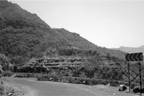
Figure 1. The panoramic view of the hill slope.
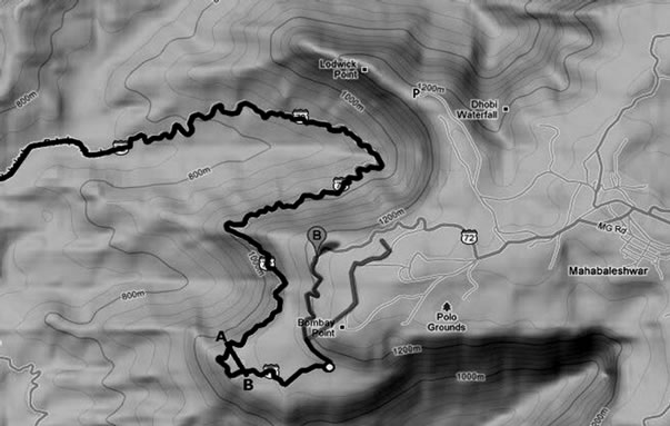
Figure 2. The Google image of the study area, portraying the analyzed slope A-B (courtesy: earth. google. com).
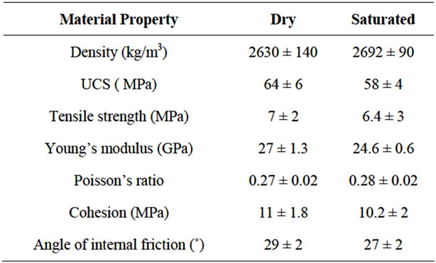
Table 1. Intact rock properties of Mahabaleshwar basalt.
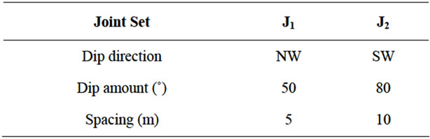
Table 2. Joint orientation in the rock mass.
as their thickness was quite thin in this section as compared to the slope dimensions.
4. Numerical Simulation
The hill slope was analyzed using a universal distinct element code (UDEC). The DEM code was used for the analysis as the rock mass is jointed with two prominent sets of joints. The DEM enables us to gauge into the behavior of jointed rock mass, which is not possible in other numerical tools [11]. The concerned area receives heavy rainfall of about 1110 mm during monsoon, which starts from July till October. Therefore, static simulation of slope was performed under both dry and saturated states using the properties given in Table 1. The geometry of the 100 m high slope was constructed in the code with the help of contour map of the area. The slope was discretized to yield 646 blocks and 2372 zones in the model (Figure 3). Apparent dip of the joints towards the direction of the slope was taken in the model. MohrCoulomb based constitutive model has been used for the present mode [15]. The factor of safety (FOS) was calculated using the shear strength reduction technique in the UDEC [30-32].
A maximum velocity vector of 4.8 × 10⁻² m/s while a maximum displacement of 1.4 × 10⁻¹ m was developed for the slope (Figures 4 and 5). The FOS calculated after simulation was 1.25 (Figure 4).
Under the saturated condition, an FOS of 0.92 was estimated. The result shows that sliding took place in the upper reaches of the slope. The slope had failed along the joint set J1, with development of tension crack along joint set J2 at the top surface of the slope in failure mode I and II (Figure 6).
The maximum displacement of 7.03 × 10⁻¹ m was estimated in the saturated condition (Figure 7). The joints are at their shear limit at these states indicates probability of yielding condition.
5. Results and Discussion
The Mahabaleshwar hill slope was analyzed in UDEC for its stability and deformation characters. The hill slope was found to be stable under the dry condition with an FOS of 1.25, while the FOS for saturated condition was 0.92. This shows the effect of rain/water on reduction in shear strength. The FOS reduced by 25.4% from dry to wet (Table 3). For the dry condition, the model took 44,680 zero cycles in 18.6 seconds to attain the equilibrium condition of almost zero unbalanced force (Figure 8). The saturated model had to undergo 117,820 to reach the equilibrium condition in 50.1 seconds (Figure 9).
After 13,252 cycles, the maximum displacement is recorded for the lower road cut, while the minimum displacement is of the top slope surface in dry slope (Figure 10). The displacement along the slope attains a constant value after 1 second in the model. In the saturated condition, the maximum displacement is recorded for the first two surfaces along the slope (Figure 11). The displacement
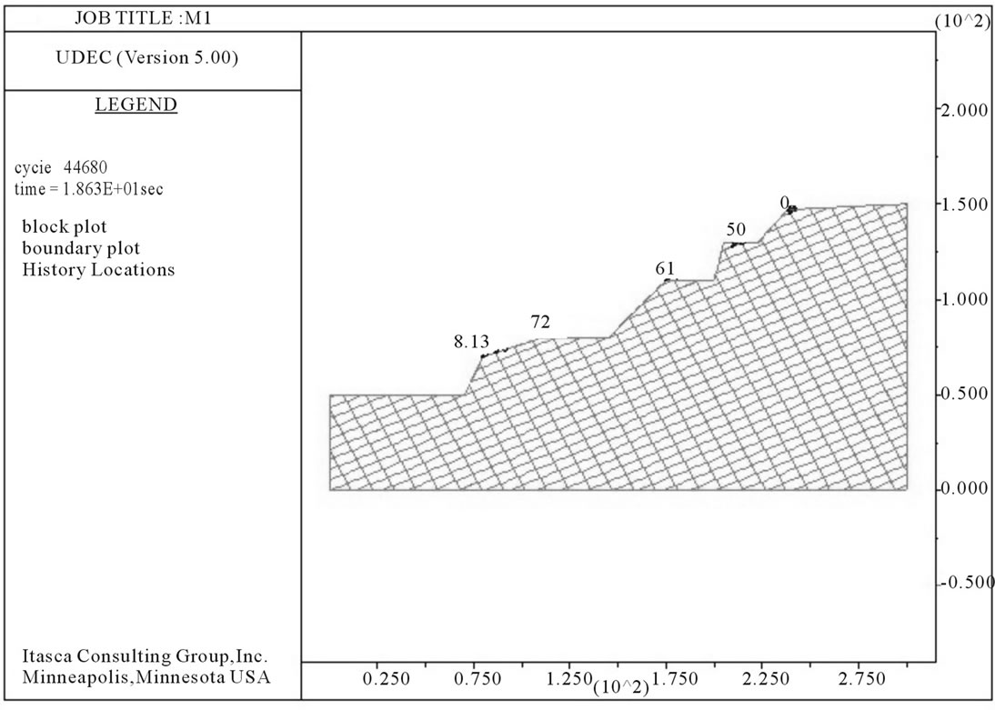
Figure 3. The modeled geometry of the hill slope with monitoring locations.
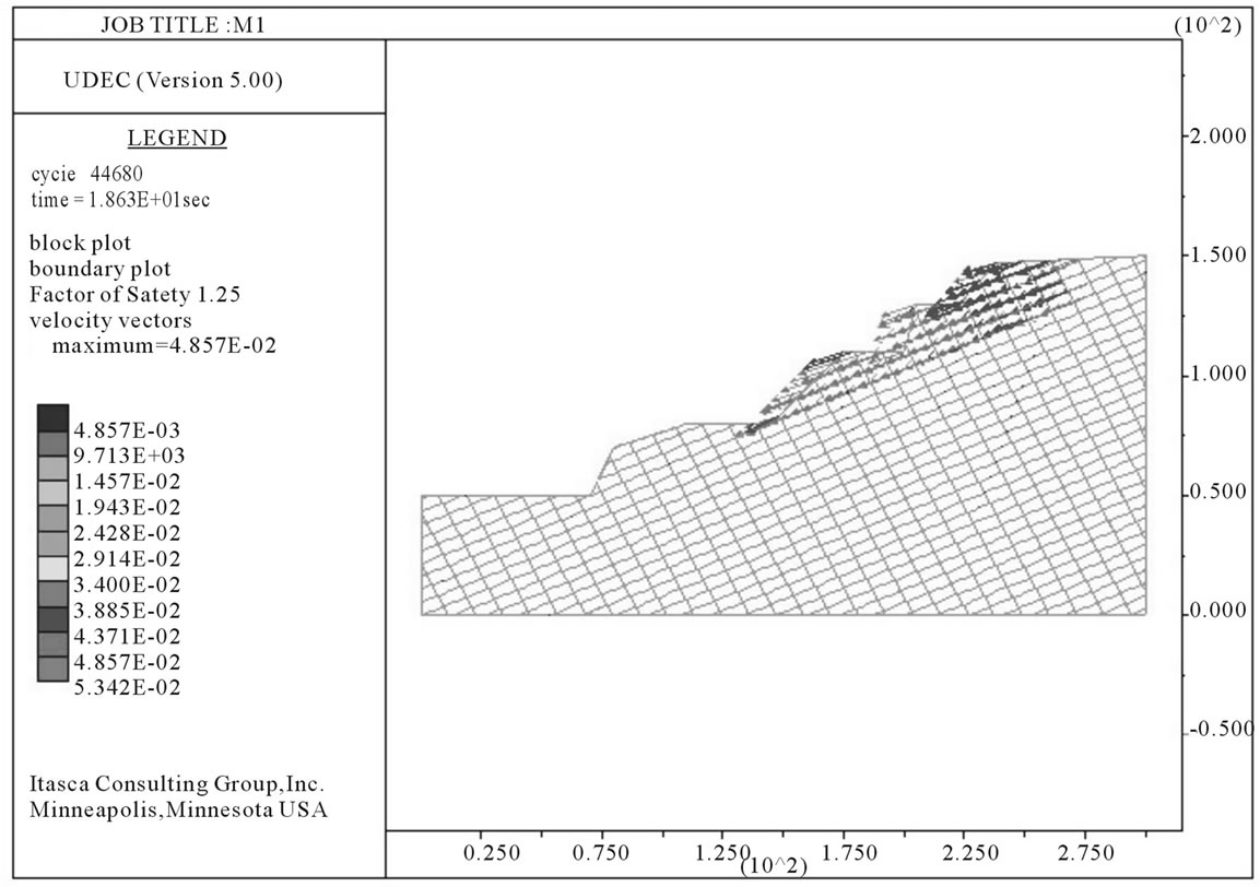
Figure 4. UDEC plot for the hill slope in dry condition depicting the velocity vectors.
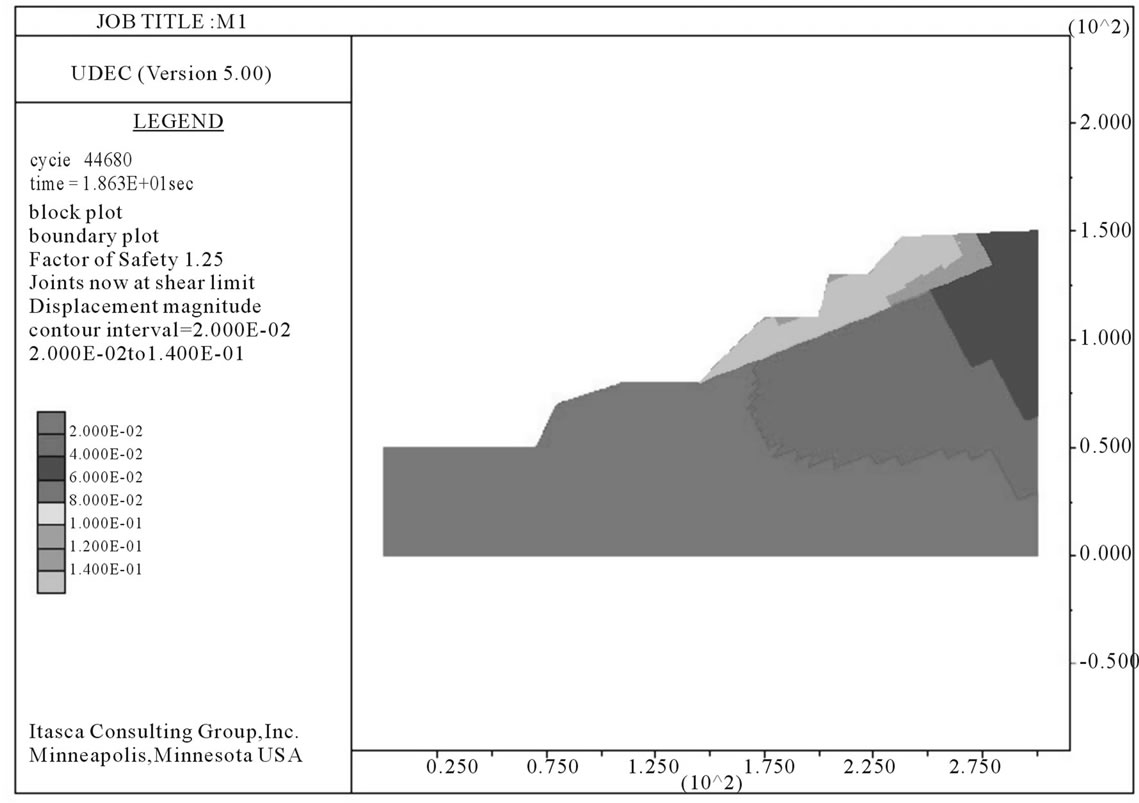
Figure 5. UDEC plot for the hill slope in dry condition depicting the displacement contours.
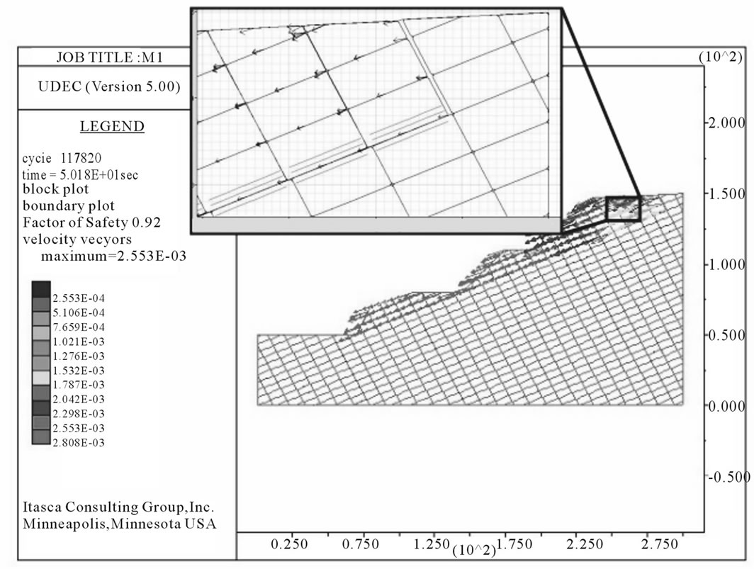
Figure 6. UDEC plot for the hill slope in saturated condition depicting the velocity vectors (Inset shows detached zone).
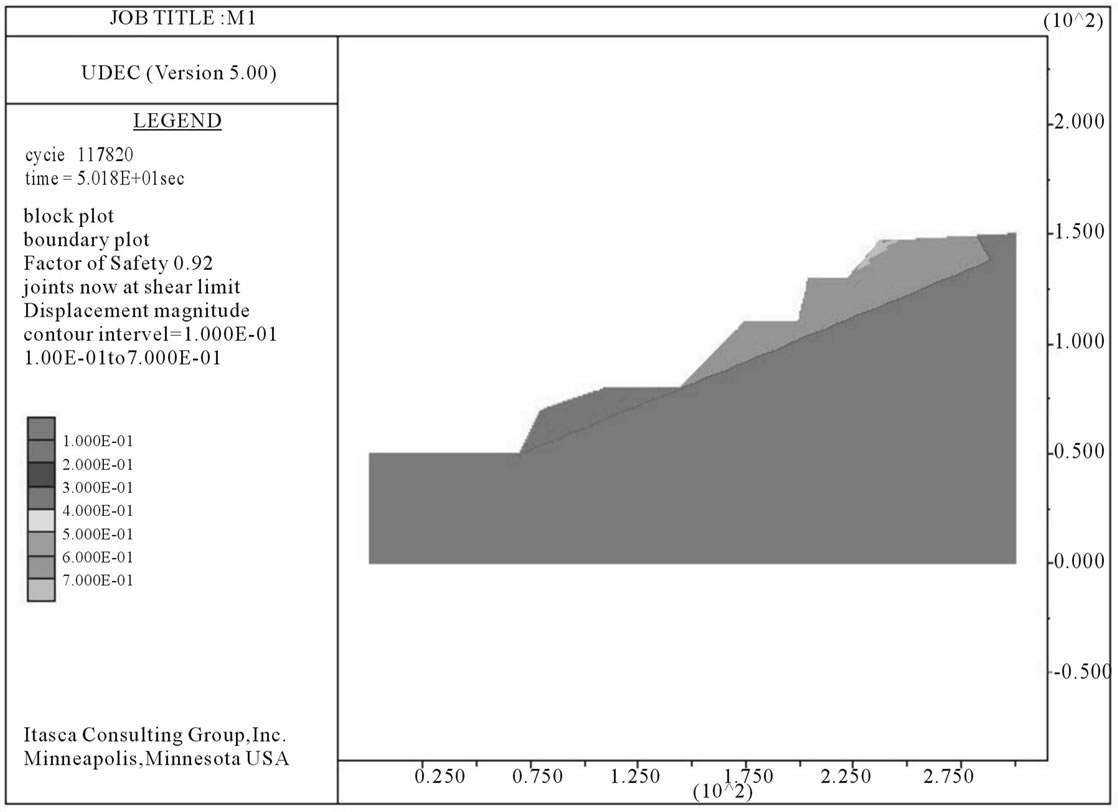
Figure 7. UDEC plot for the hill slope in saturated condition depicting the displacement contours.
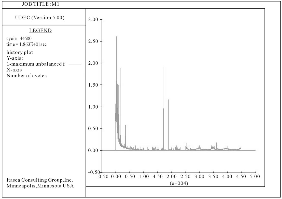
Figure 8. Unbalanced force vs cycle plot for the dry condition.
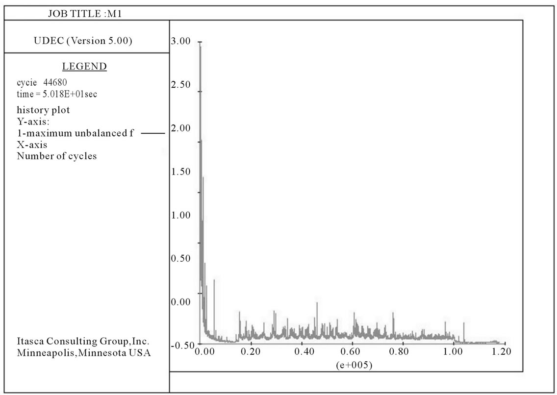
Figure 9. Unbalanced force vs cycle plot for the saturated condition.
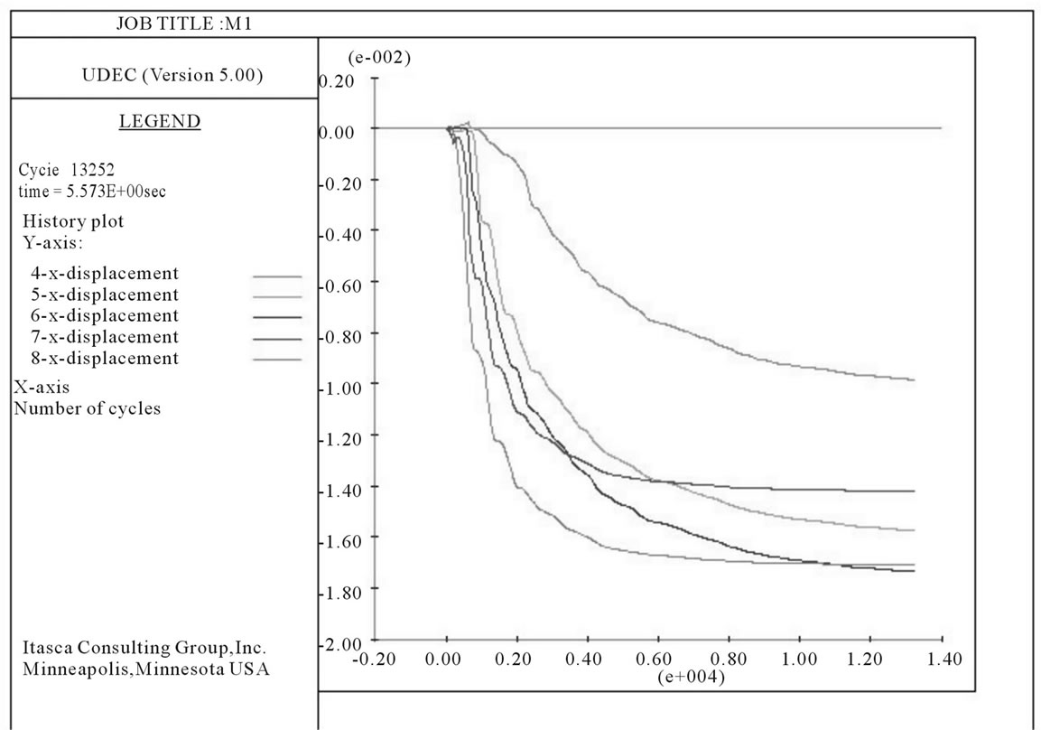
Figure 10. The X displacement along monitoring points on the hill slope for dry condition.
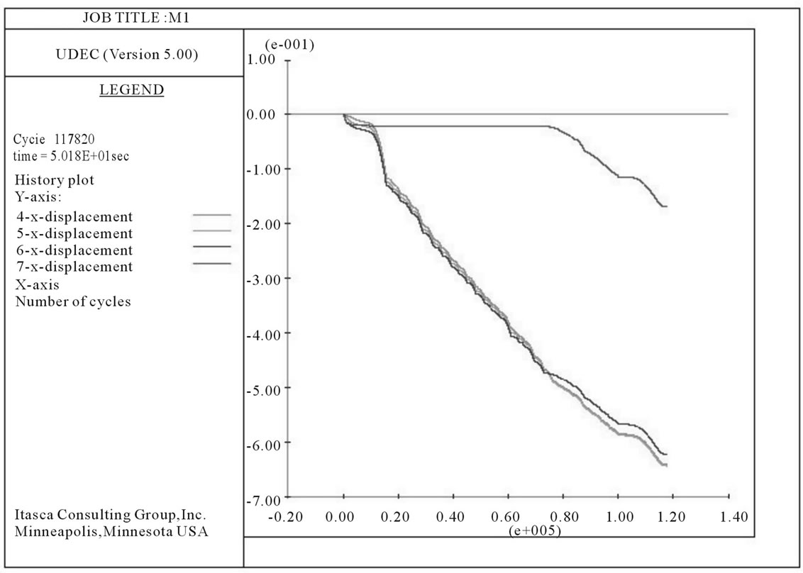
Figure 11. The X displacement along monitoring points for saturated condition.
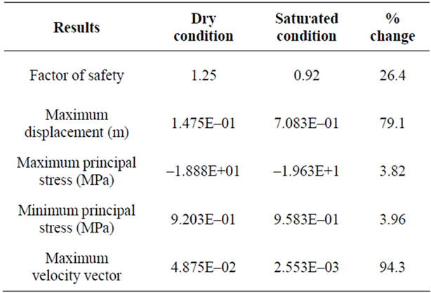
Table 3. Comparative results of the dry and saturated DEM models for the hill slope.
plots in the saturated condition don’t attain a constant value but keep on increasing due to progressive failure in the rock slope. The least displacement has been recorded for the lowest bench in the hill slope. This signifies the movement of upper part of the slope along a well-defined joint plane. The slip plane wedges out along the second cut slope on the hill indicating a large scale plane failure.
6. Conclusion
A 100 m high natural hill slope composed of basalt was analyzed using the DEM code for dry and saturated conditions using the coulomb constitutive model. Under the dry condition, the slope is relatively unstable with an FOS of 1.25 because of steep slope and heavy vehicle movement. The slope fails under the saturated conditions. The region is already infested with some major and minor slides along the road cuts. Although the total slope collapse has not taken place in the area, but due to consistent deterioration and human intervention the possibility of it cannot be ruled out. The DEM model has also put light on important deformational characteristics of the slope, for future protection and prevention to save the loss of life and traffic congestion. Since the area falls under Seismic zone III, coupled with the vibration produced by the daily traffic, dynamic modeling of the area is also required. The dynamic analysis can give fruitful insight into the stability of the slopes, which is left for future consideration
7. Acknowledgements
The authors would like to thank DST, New Delhi, India for providing the financial assistance to conduct the study.
REFERENCES
- R. Bhasin and A. M. Kaynia, “Static and Dynamic Simulation of a 700-m High Rock Slope Failure in Western Norway,” Engineering Geology, Vol. 71, No. 3-4, 2004, pp. 213-226. doi:10.1016/S0013-7952(03)00135-2
- Y. Lin, D. Zhu, Q. Deng and Q. He, “Collapse Analysis of Jointed Rock Slope Based on UDEC Software and Practical Seismic Load,” International Conference on Advances in Computational Modeling and Simulation, Vol. 31, 2012, pp. 441-416.
- M. Souley and F. Homand, “Stability of Jointed Rock Masses Evaluated by UDEC with an Extended SaebAmadei Constitutive Law,” International Journal of Rock Mechanics and Mining Sciences, Vol. 33, No. 3, 1996, pp. 233-244. doi:10.1016/0148-9062(95)00063-1
- T. N. Singh, V. Bhardwaj, L. Dhonta and K. Sarkar, “Numerical Analysis of Instability of Slope near Rudraprayag Area,” Journal of Engineering Geology, Vol. 34, No. 1-4, 2007, pp. 33-42.
- A. Kainthola, D. Verma, S. S. Gupte and T. N. Singh, “A Coal Mine Dump Stability Analysis: A Case Study,” International Journal of Geomaterialogy, Vol. 1, 2011, pp. 1-13.
- D. Verma, R. Thareja, A. Kainthola and T. N. Singh, “Evaluation of Open Pit Mine Slope Stability Analysis,” International Journal of Earth Sciences and Engineering, Vol. 4, No. 4, 2011, pp. 590-600.
- K. Sarkar and T. N. Singh, “Evaluation of Instability Analysis of Slope: A Numerical Approach,” Mining Engineering Journal, Vol. 8, No. 10, 2007, pp. 11-31.
- R. Bhasin and K. Høeg, “Parametric Study for a Large Cavern in Jointed Rock Using a Distinct Element Model (UDEC-BB),” International Journal of Rock Mechanics and Mining Sciences, Vol. 35, No. 1, 1998, pp. 17-29. doi:10.1016/S0148-9062(97)00312-4
- X. B. Zhao, J. Zhao, J. G. Cai and A. M. Hefny, “UDEC Modelling on Wave Propagation across Fractured Rock Masses,” Computers and Geotechnics, Vol. 35, No. 1, 2008, pp. 97-104. doi:10.1016/j.compgeo.2007.01.001
- E. Hoek, J. Read, A. Karzulovic and Z. Y. Chen, “Rock Slopes in Civil and Mining Engineering,” International Conference on Geotechnical and Geological Engineering, Melbourne, 2000, pp. 1-17.
- J. P. Aglawe and A. G. Corkum, “Application of Distinct Element Analysis in Slope Stability Problems,” Indo-Norwegian Workshop on Seismic Hazard and Risk Assessment, New Delhi, 2006.
- P. A. Cundall, “A Computer Model for Simulating Progressive Large Scale Movements in Blocky Rock System,” International Proceedings Symposium, ISRM, Nancy, 1971, pp. 128-132.
- P. A. Cundall, “UDEC: A Generalized Distinct Element Program for Modelling Jointed Rock,” Report PCAR-I-80, Peter Cundall Associates Report, European Research Office, US Army, Contract, 1980, DAJA37-79-C-0548.
- S. Nichol, O. Hungr and S. Evans, “Large-Scale Brittle and Ductile Toppling of Rock Slopes,” Canadian Geotechnical Journal, Vol. 39, No. 4, 2002, pp. 773-788. doi:10.1139/t02-027
- UDEC 5.0, “Universal Distinct Element Code User’s Guide,” Itasca Consulting Group Inc., Minneapolis, Minnesota, 2011.
- C. Zhang, O. K. Pekau, J. Feng and W. Guanglun, “Application of Distinct Element Method in Dynamic Analysis of High Rock Slopes and Blocky Structures,” Soil Division Earthquake Engineering, Vol. 16, No. 6, 1997, pp. 385-394. doi:10.1016/S0267-7261(97)00012-2
- T. Easki, Y. Jiang, T. N. Bhattarai, T. Maeda, A. Nozaki and T. Mizokami, “Modelling Jointed Rock Masses and Prediction of Slope Stabilities by DEM,” Proceedings of the 37th US Rock Mechanics Symposium, Vail, 1999, pp. 83-90.
- V. Kveldsvik, A. M. Kaynia, F. Nadim, R. Bhasin, N. Bjørn and H. H. Einstein, “Dynamic Distinct-Element Analysis of the 800 m High Åknes Rock Slope,” International Journal of Rock Mechanics and Mining Sciences, Vol. 46, No. 4, 2009, pp. 686-698. doi:10.1016/j.ijrmms.2008.10.007
- G. W. Rathod, A. K. Shrivastava and K. S. Rao, “Distinct Element Modelling for High Rock Slopes in Static and Dynamic Conditions: A Case Study,” GeoRisk, ASCE, 2011.
- J. E. Beane, C. A. Turner and P. R. Hooper, “Stratigraphy, Composition and Form of the Deccan Basalts, Western Ghats, India,” Bulletin of Volcanology, Vol. 48, 1986, pp. 61-83. doi:10.1007/BF01073513
- S. Najafi, K. G. Cox and R. N. Sukeshwala, “Geology and Geochemistry of the Basalt Flows, Deccan Traps of the Mahad-Mahabaleshwar Section, India,” In: K. V. Subbarao and R. N. Sukeshwala, Eds., Geological Society of India, Vol. 3, 1981, pp. 300-315.
- ISRM, “Rock Characterization Testing and Monitoring, ISRM Suggested Methods,” International Society for Rock Mechhanics, 1981, p. 211.
- ISRM, “Suggested Methods for Determining Tensile Strength of Rock Materials,” International Journal of Rock Mechanics and Mining Sciences & Geomechanics Abstracts, Vol. 15, No. 3, 1978, pp. 99-103. doi:10.1016/0148-9062(78)90003-7
- ISRM, “Suggested Methods for Determining Swelling and Slake Durability Index Properties,” International Journal of Rock Mechanics and Mining Sciences, Vol. 16, 1978, pp. 151-156.
- ISRM, “Commission on Standardization of Laboratory and Field Tests, Suggested Methods for Determining Sound Velocity,” International Journal of Rock Mechanics and Mining Sciences & Geomechanics Abstracts, Vol. 15, No. 3, 1978, pp. 53-58. doi:10.1016/0148-9062(78)90049-9
- ISRM, “Commission on Standardization of Laboratory and Field Tests, Suggested Methods for Determining Water Content, Porosity, Density, Absorption and Related Properties and Swelling and Slake-Durability Index Properties,” International Journal of Rock Mechanics and Mining Sciences & Geomechanics Abstracts, Vol. 16, 1979, pp. 141-156. doi:10.1016/0148-9062(79)90188-8
- ISRM, “Rock Characterization Testing and Monitoring, ISRM Suggested Methods,” International Journal of Rock Mechanics and Mining Sciences, 1981, p. 211.
- ISRM, “Suggested Method for Determining the Uniaxial Compressive Strength of Rock Materials, Rock Characterization, Testing and Monitoring,” International Journal of Rock Mechanics and Mining Sciences & Geomechanics Abstracts, 1981, p. 113.
- ISRM, “Suggested Methods for Determining Shear Strength,” In: E. T. Brown, Ed., Rock Characterization, Testing and Monitoring, Pergamon Press, Oxford,1981, pp. 129-140.
- I. B. Donald and S. K. Giam, “Application of the Nodal Displacement Method to Slope Stability Analysis,” Proceedings of the 5th Australia-New Zealand Conference on Geomechanics, Sydney, 1988, pp. 456-460.
- T. Matsui and K. C. San, “Finite Element Slope Stability Analysis by Shear Strength Reduction Technique,” Soils and Foundations, Vol. 32, No. 1, 1992, pp. 59-70. doi:10.3208/sandf1972.32.59
- K. Ugai and D. Leshchinsky, “Three-Dimensional Limit Equilibrium and Finite Element Analyses: A Comparison of Results,” Soils and Foundations, Vol. 35, No. 4, 1995, pp. 1-7. doi:10.3208/sandf.35.4_1
NOTES
*Corresponding author.