American Journal of Computational Mathematics
Vol.3 No.4(2013), Article ID:39808,13 pages DOI:10.4236/ajcm.2013.34041
Unsteady Incompressible Couette Flow Problem for the Eyring-Powell Model with Porous Walls
Faculty of Numerical Sciences, Islamia College University, Peshawar, Pakistan
Email: haiderzaman67@yahoo.com
Copyright © 2013 Haider Zaman et al. This is an open access article distributed under the Creative Commons Attribution License, which permits unrestricted use, distribution, and reproduction in any medium, provided the original work is properly cited.
Received October 8, 2013; revised November 8, 2013; accepted November 17, 2013
Keywords: Unsteady; Couette Flow; Eyring-Powell Model; Pade Approximants; Porous Plates
ABSTRACT
This work is concerned with the influence of uniform suction or injection on unsteady incompressible Couette flow for the Eyring-Powell model. The resulting unsteady problem for horizontal velocity field is solved by means of homotopy analysis method (HAM). The characteristics of the horizontal velocity field and wall shear stress are analyzed and discussed. Pade approximants and Taylor polynomials are also found for velocity profile and are used to make the maximum error as small as possible. The graphs of the error for the Pade approximation and Taylor approximation are drawn and discussed. Convergence of the series solution is also discussed with the help of  and interval of convergence is also found.
1. Introduction
The study of non-Newtonian fluids has generated much interest in recent years in view of their numerous industrial applications, especially in polymer and chemical industries. The examples of such fluids includes various suspensions such as coal-water or coal-oil slurries, molten plastics, polymer solutions, food products, glues, paints, printing inks, soaps, shampoos, toothpastes, clay coating, grease, cosmetic products, custard, blood, etc. Some interesting studies of non-Newtonian fluids are given by Hayat et al. [1-5], Asghar et al. [6], Khan et al. [7,8], Cortell [9,10], Ayub et al. [11-13], Ariel et al. [14], Rajagopal [15-17], Erdogan [18], Siddiqui and Kaloni [19] and Fetecau [20]. Couette flow is an important type of flow in the history of fluid mechanics. Researchers have deep interest in this flow and they study it in many ways. Some important studies about this flow are as follows:
Fang [21] studied Couette flow problem for unsteady incompressible viscous fluid bounded by porous walls. Khaled and Vafai [22] considered Stokes and Couette flows due to an oscillating wall. Asghar et al. [23] discussed unsteady Couette flow in a second grade fluid with variable material properties. Hayat et al. [24] examined the axial Couette flow problem of an electrically conducting fluid in an annulus. Hayat and Kara [25]
studied Couette flow of a third-grade fluid with variable magnetic field. Seth et al. [26] presented Couette flow problem for a porous channel. Bhaskara and Bathaiah [27] have analyzed Couette flow problem for flow through a porous straight channel with MHD and Hall effects. Das et al. [28] considered unsteady Couette flow problem in a rotating system. Ganapathy [29] presented a note on the oscillatory Couette flow in a rotating system. Guria [30, 31] discussed Couette flow problem for rotating and oscillatory flow. Sigh [32] found a periodic solution for oscillatory Couette flow.
The Eyring-Powell model [33] although more mathematically complex, has certain advantages over the Second grade, Maxwell, Power-law and Micropolar fluid models. Eyring-Powell model is derived from the kinetic theory of liquids rather than the empirical relations. It correctly reduces to Newtonian behavior for low and high shear stress. Recently, Eldabe et al. [34] and Zueco and Beg [35] discussed the non-Newtonian fluid flow under the effect of couple stresses between two parallel plates using Eyring-Powell model. Prasad et al. [36] studied momentum and heat transfer of a non-Newtonian Eyring-Powell fluid over a non-isothermal stretching sheet. Patel and Timol [37] presented a numerical treatment of MHD Eyring-Powell fluid flow. Sirohi et al. [38] studied Eyring-Powell fluid flow past a 90˚ wedge. Javed et al. [39] discussed flow of an Eyring-Powell nonNewtonian fluid over a stretching sheet. Noreen and Qasim [40] analyzed peristaltic flow of MHD EyringPowell fluid in a channel.
Keeping this all in view, in the present paper, the authors envisage studying the time-dependent Couette flow of incompressible non-Newtonian Eyring-Powell model with porous walls. The resulting unsteady problem is solved by means of homotopy analysis method (HAM) [41-58], which is very powerful and efficient in finding the analytic solutions for a wide class of nonlinear differential equations. The method gives more realistic series solution that converges very rapidly in physical problems. The convergence region for the series solution is found with the help of . For a given amount of computational effort, one can usually construct a rational approximation that has smaller overall error in given domain than a polynomial approximation [59]. Our goal is to make the maximum error as small as possible. For this purpose, Pade approximants and Taylor polynomials are found. The graphs of the error for Pade approximants and Taylor polynomials are plotted and it is observed that maximum absolute error occurs at the end point
 . The graphs for the horizontal velocity profile and shear stress at the wall for injection/suction are drawn and discussed in detail. The tables for the initial slope and wall shear stress are also constructed and discussed. More significantly, the series solution clearly demonstrates how various physical parameters play their part in determining properties of the flow.
2. Mathematical Description of the Problem
Consider an unsteady, incomprssible, non-Newtonian, Couette flow problem for the Eyring-Powell model, in which the bottom wall is fixed and subjected to a mass injection velocity  and there is mass suction velocity
  at the top wall,
  correspond to injection and
  correspond to suction. The top plate is stationary when
 , there is only mass transfer in the transverse direction, say
  direction. At
 , the top wall is started impulsively to a constant velocity
 . The Eyring-Powell model is derived from the theory of rate processes, which describes the shear of a non-Newtonian flow. The Eyring-Powell model can be used in some cases to describe the viscous behavior of polymer solutions and viscoelastic suspensions over a wide range of shear rates. The stress tensor in the Eyring-Powell model for non-Newtonian fluids is given by [33]
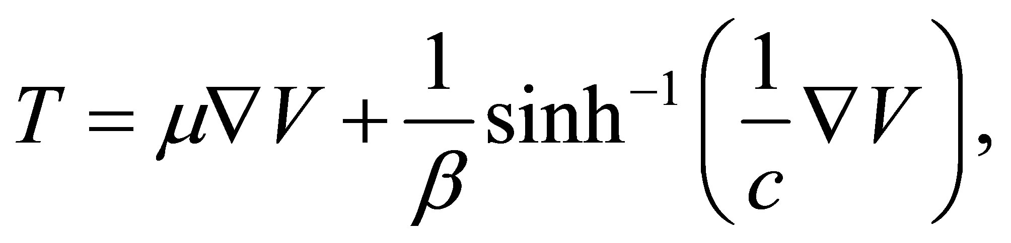 (1)
(1)
where  is the dynamic viscosity,
  and
and  are the characteristics of the Eyring-Powell model. Taking the second order approximation of the function
  as
as
 (2)
(2)
The governing equation for this problem can be obtained as
 (3)
(3)
 (4)
(4)
where  is the kinematic viscosity,
  is the density of the fluid, bottom wall is located at
 , top wall is located at
  and
and  is the velocity at the upper wall. Equations (3) and (4) can be non-dimensionalized by defining
 (5)
(5)
Then Equations (3) and (4) become
 (6)
(6)
 (7)
(7)
where  is the Reynolds number,
  is the fluid parameter and
 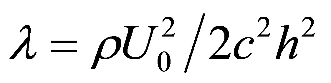 is the local non-Newtonian parameter based on velocity of plate
 . Using stream function relations with velocity [60] Equations (6) and (7) become
 (8)
(8)
 (9)
(9)
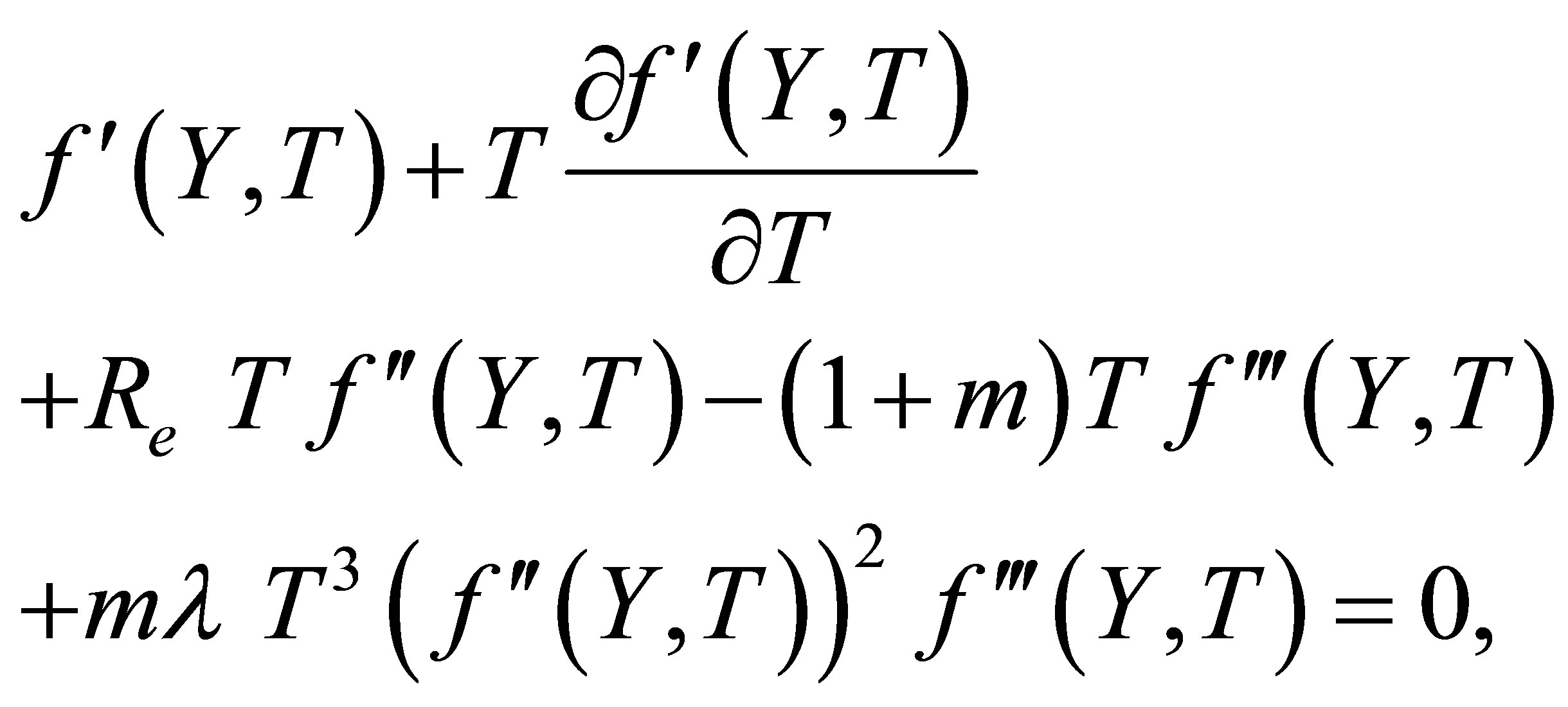
where,  is the reduced stream function and prime denotes ordinary derivative w. r. t
 . When
 , Equation (8) becomes
where  is some arbitrary unknown function of
 .
.
3. Analytic Solution
To start with the homotopy analysis method it is very much important to choose an initial guess approximation and a linear operator. Therefore, due to the boundary conditions (9) it is reasonable to choose the initial guess approximation
 (10)
(10)
and the linear operator
 (11)
(11)
which satisfies the following property:
 (12)
(12)
where  and
and  are arbitrary constants. If
  is an embedding parameter and
  is auxiliary non zero parameter then the so-called zero-order deformation equation is
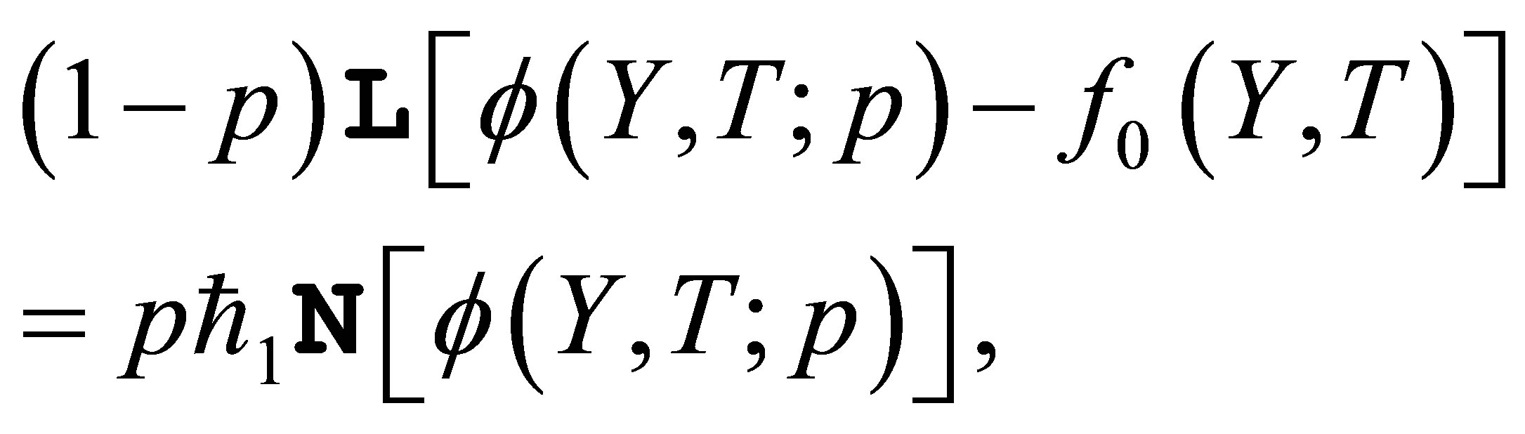 (13)
(13)
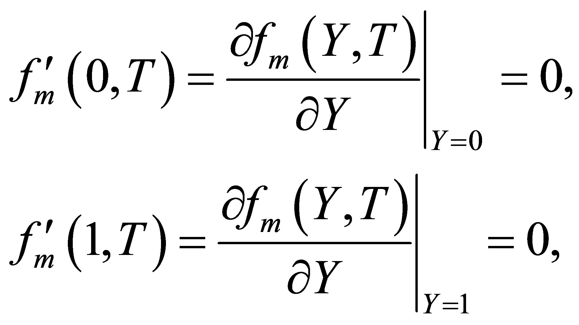
subject to boundary conditions
 (14)
(14)
where
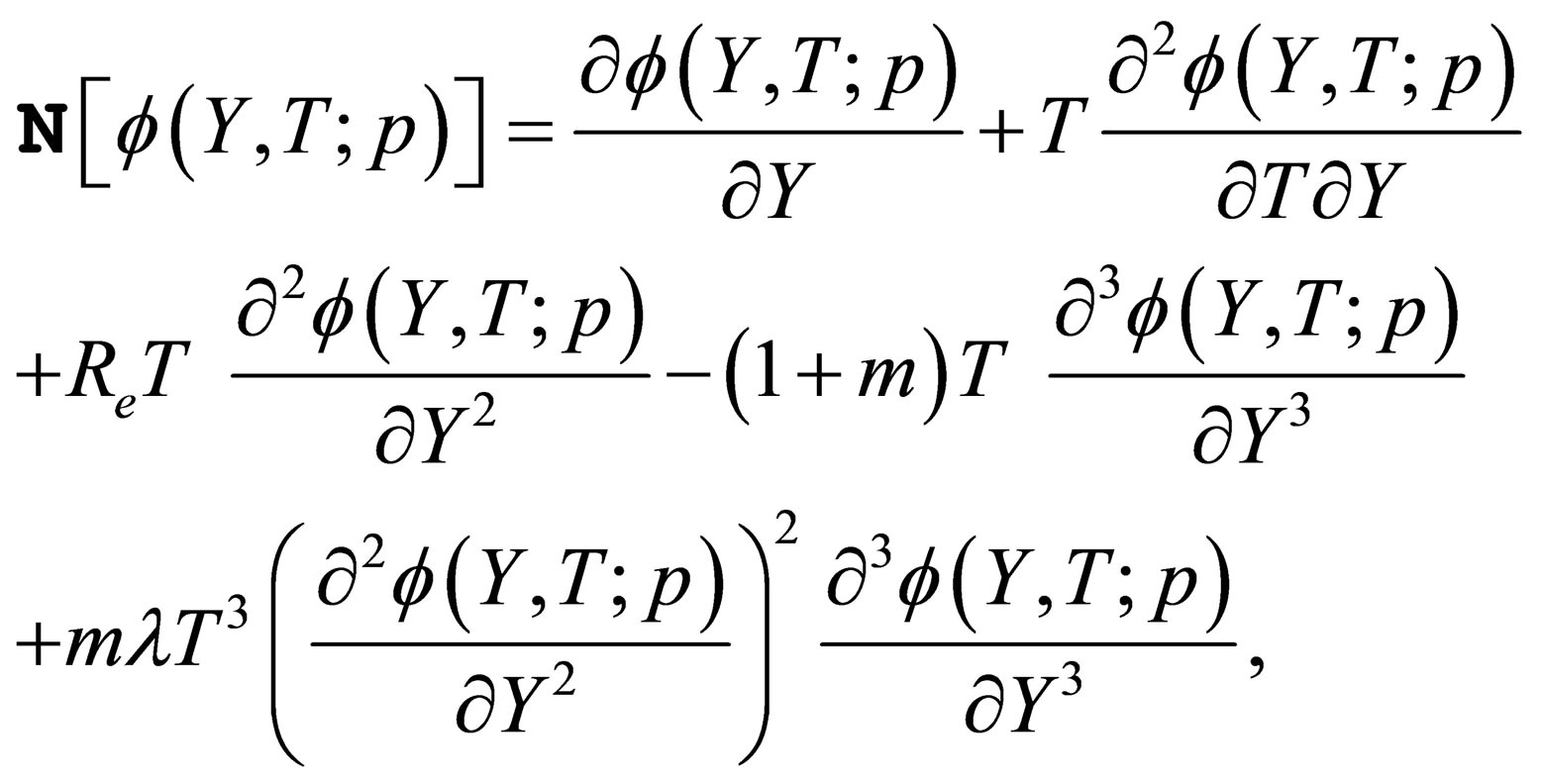 (15)
(15)
and when  and
and , then
 (16)
(16)
As the embedding parameter  increases from 0 to 1,
  varies (or deforms) from the initial approximation
  to the solution
 . Using Taylor’s theorem and Equation (16), one obtains
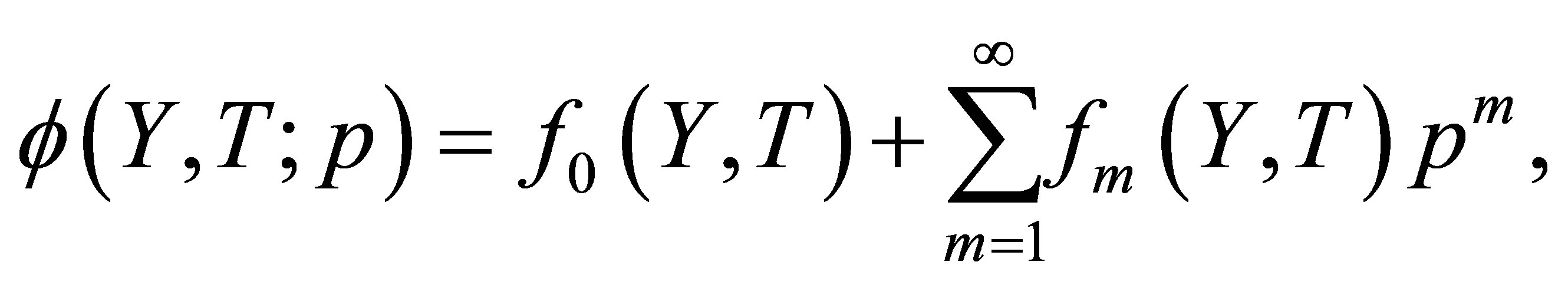 (17)
(17)
in which
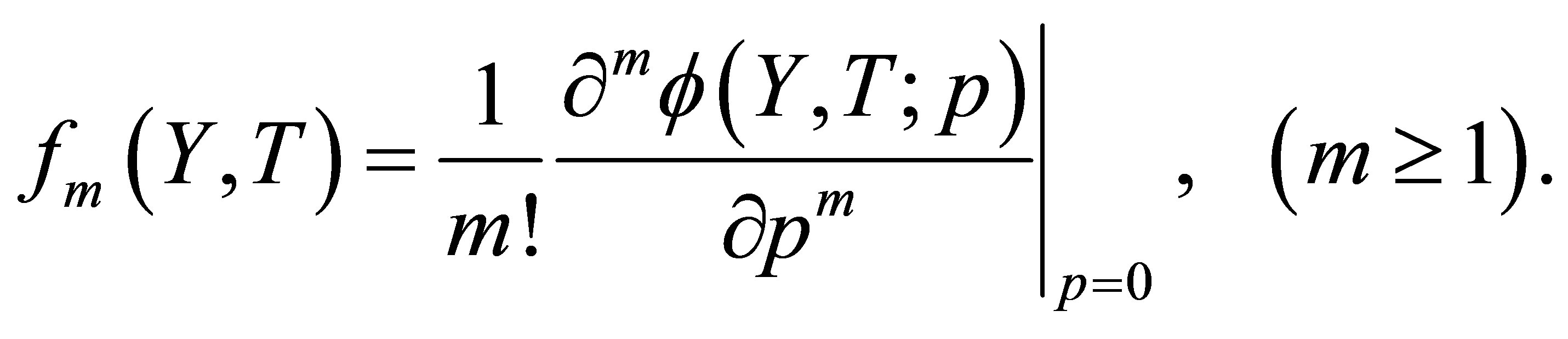 (18)
(18)
Clearly, the convergence of the series (17) depends upon . Assume that
  is selected such that the series (17) is convergent at
 , then due to equation (16) we have
 (19)
(19)
For the  order deformation problem, we differentiate Equations (13) and (14)
  w.r.t
w.r.t  and then setting
  and finally dividing it by
  the
the  deformation equation for
  is given by
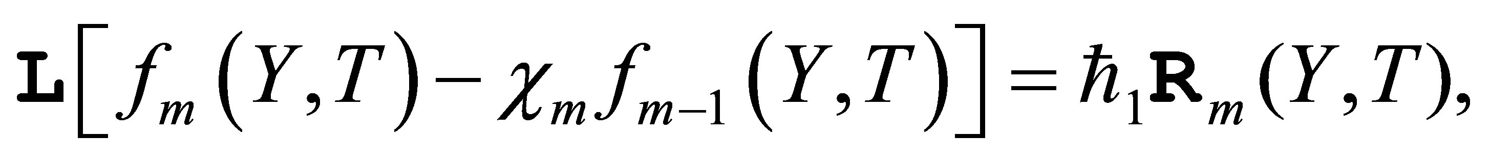 (20)
(20)
 (21)
(21)
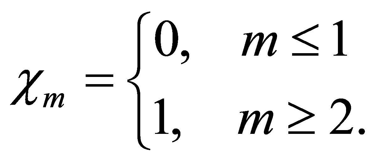
where
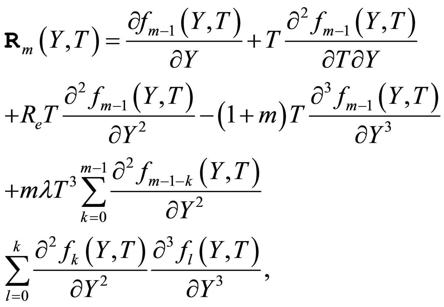 (22)
(22)
 (23)
(23)
Following the HAM and trying higher iterations with the unique and proper assignment of the results converge to the exact solution:
 (24)
(24)
using the symbolic computation software such as MATHEMATICA, MATLAB or MAPLE to solve the system of linear equations, (20), with the boundary conditions (21), and successively obtain
4. Convergence of the Analytic Solution
The auxiliary parameter  gives the convergence region and rate of approximation for the homotopy analysis method for above problem. For this purpose, the
  is plotted for above problem. It is obvious from Figure 1 that the range for the admissible values for
  is
is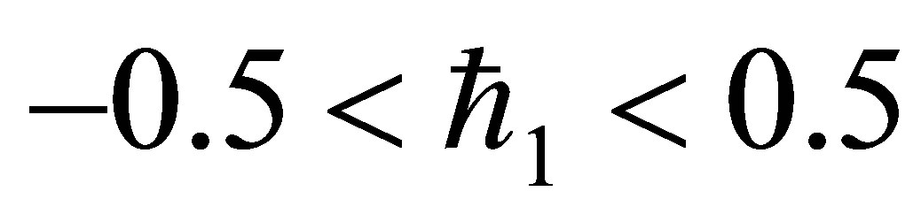 . The solution series converges in the whole region of
  and
and  for
for  or
or .
.
5. Pade Approximation
Pade approximants make up the best approximation of a function in the form of a rational function of a given order. Pade approximation helps us in improving the ac curacy of approximate solution available in the form of a polynomial. Pade approximants are better approximation of a function than its Taylor series, they work even in those cases where Taylor series does not converge. Pade
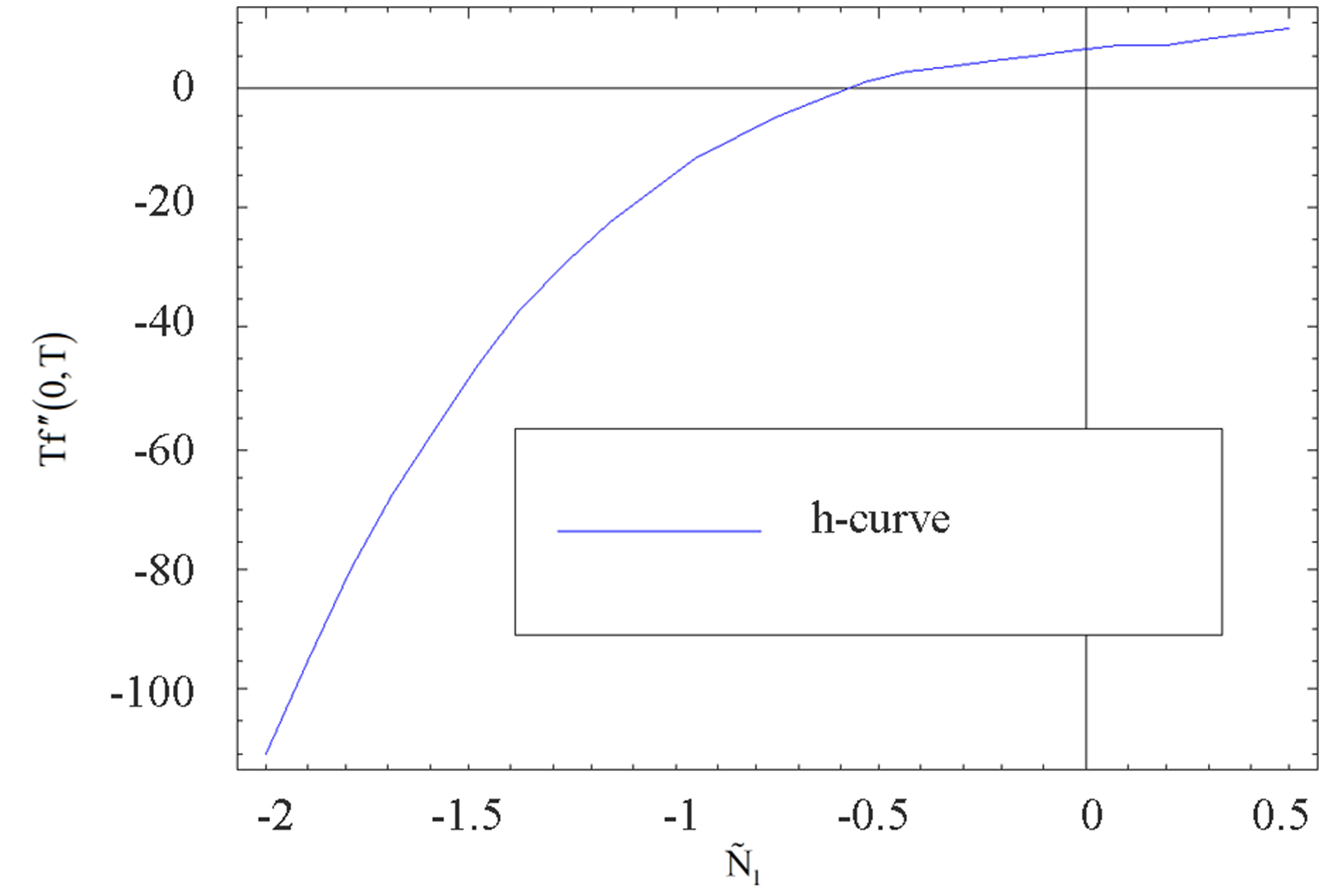
Figure 1.  -curve for the stream function
  at
at ,
,  ,
,  and
and .
.
 (25)
(25)
approximations are also used to enlarge the interval of convergence of approximate series solution [61]. A standard MATHEMATICA routine can be used to find Pade approximant for the function . A
. A  Pade approximant for the solution in Equation (24) at
 ,
,  ,
,  ,
,  ,
,  can be written as
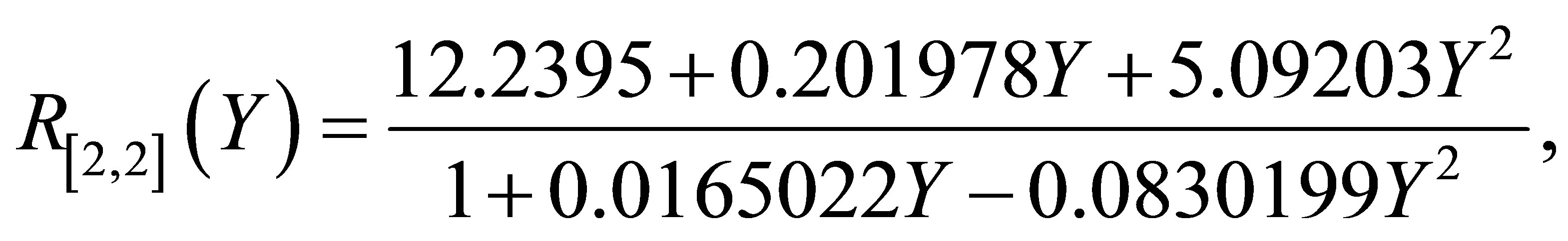 (26)
(26)
Figure 2 depicts the graph of  and its Pade approximant
 . From Figure 2 we observe that the difference between the HAM solution
  and Pade approximate solution
  is so small as to be invisible on this scale. The graph of the error
 over
over  for the Pade approximant
  is shown in Figure 3. We note that the maximum absolute error occur at the end point,
 . The Taylor polynomials for

Figure 2. The graph of  and its Pade approximation
 .
.
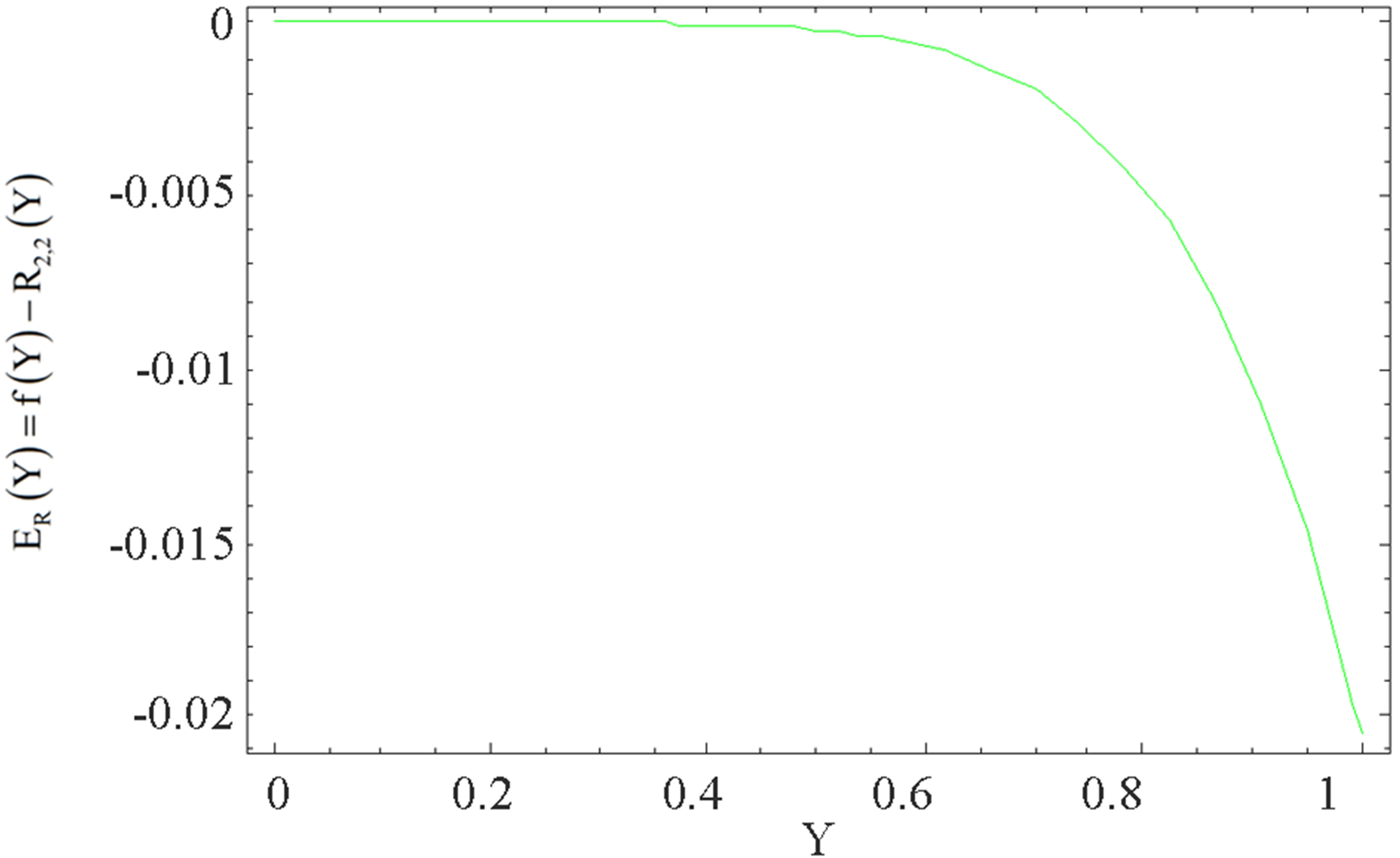
Figure 3. The graph of the error  for the Pade approximation
 .
.
 of degree
  and
and  at
at ,
,  ,
,  ,
,  ,
,  obtained as
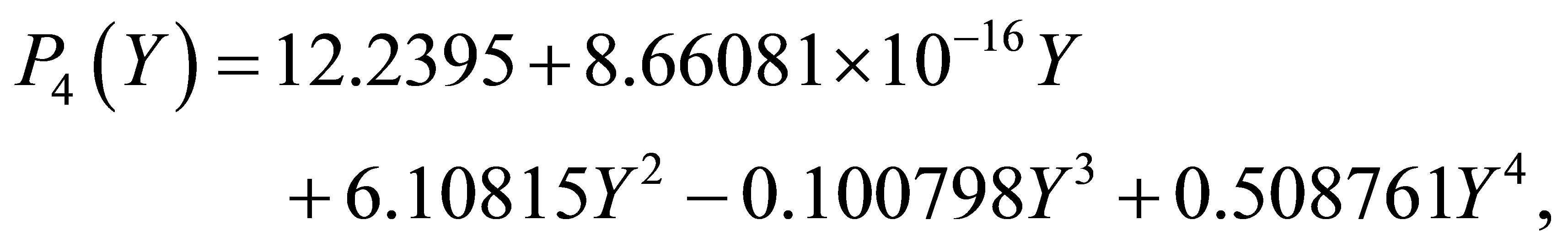 (27)
(27)
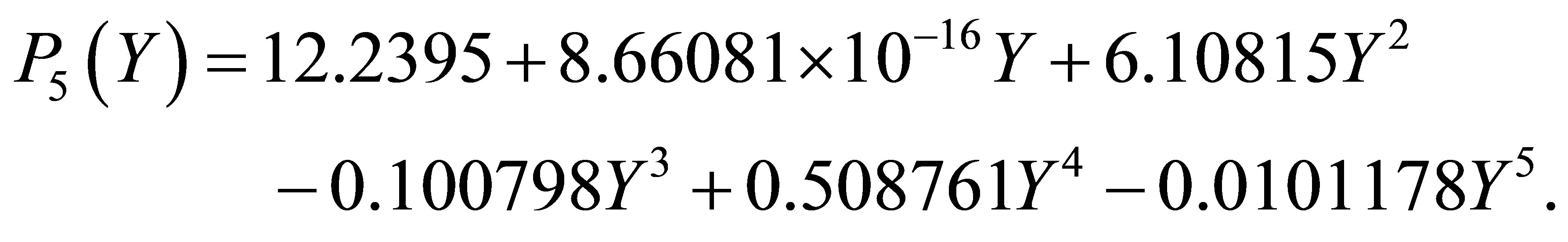 (28)
(28)
Figure 4 illustrates that the difference between  and
and  is invisible on this scale. Figure 5 indicates the graph of the error
  over
over  for the Taylor approximation
 . It is observed that the largest absolute error occur at the end point,
 . Figure 6" target="_self"> Figure 6 describes that the

Figure 4. The graph of  and its Taylor approximation
 .
.

Figure 5. The graph of the error  for the Taylor approximation
 .
.
difference between  and
and  is also invisible on this scale. Figure 7 explains the graph of the error
  over
over  for the Taylor approximation
 . The maximum absolute error occur at the end point,
 . It is observed that the increase in the degree of Taylor polynomial increases the maximum absolute error.
6. Graphs and Discussion
In this part we discuss the graphs for the variation of the horizontal velocity profiles  and shear stress at the wall
  with distance from the wall
  for different values of Reynolds number
 , local non-Newtonian parameter
 , fluid parameter
 , homotopy parameter
  and time
 .
.
Figures 8 and 9 describe the variation of the horizontal velocity profiles  with
with  for several values of
  by keeping
 ,
,  ,
,  and
and  fixed. Figure 8 shows that when there is mass injection
  at
at

Figure 6. The graph of  and its Taylor approximation
 .
.

Figure 7. The graph of the error  for the Taylor approximation
 .
.

Figure 8. The graph of the horizontal velocity profiles  with
with  for several values of
  and
and .
.
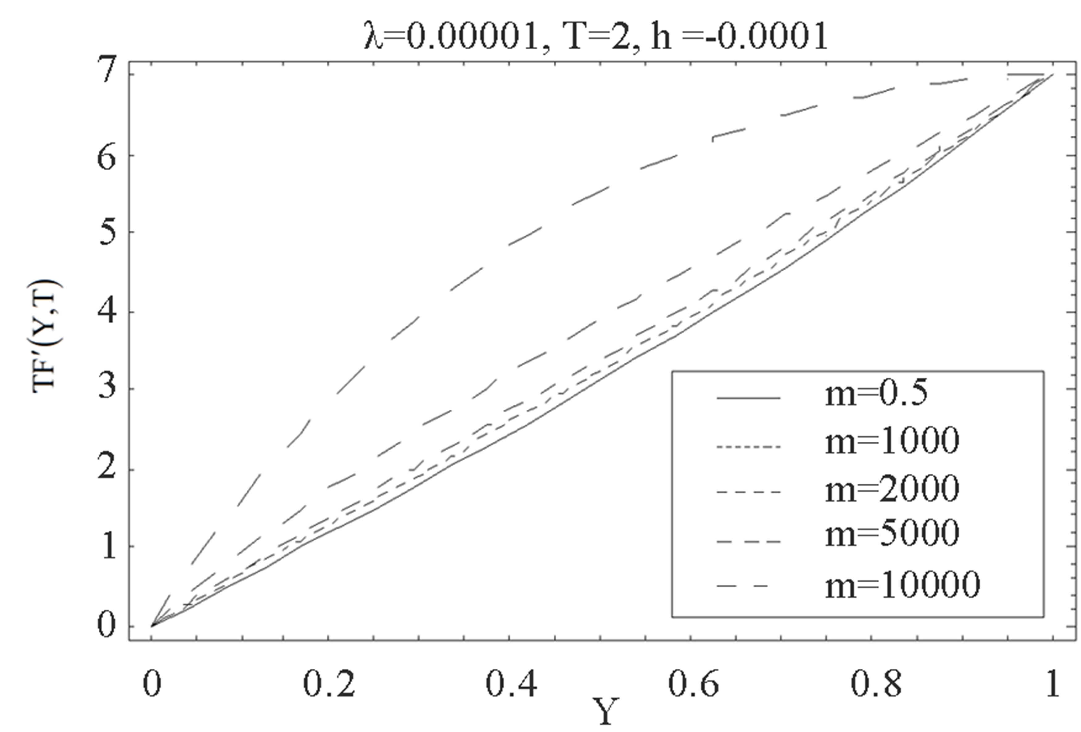
Figure 9. The graph of the horizontal velocity profiles  with
with  for several values of
  and
and .
.
the bottom wall, with increase in fluid parameter , horizontal velocity profiles
  shows decreasing trend. Figure 9 shows that when there is mass suction
  at the top wall, with increase in
 ,
,  increases at all points. Figures 10 and 11 indicate the variation of the horizontal velocity profiles
  with
with  for several values of
  by keeping
 ,
,  ,
,  and
and  fixed. Figure 10 shows that when there is mass injection
  at the bottom wall, with increase in fluid parameter
 , horizontal velocity profiles
  increases at all points. Figure 11 shows that when there is mass suction
  at the top wall, with increase in
 ,
,  increases in magnitude but have negative values, an inverted behavior is observed, which is consistent with what we expected. Figures 12 and 13 illustrate the variation of the horizontal velocity profiles
  with
with  for several values of time
 , for fixed values of
 ,
,  ,
,  and
and . Figures 12 and 13 are plotted for positive value of
 . Figure 12
shows that for mass injection  at the bottom wall, with increase in
 , horizontal velocity profiles
  shows increasing trend in magnitude but have negative values. From Figure 13 it is clear that for mass

Figure 10. The graph of the horizontal velocity profiles  with
with  for several values of
  and
and .
.
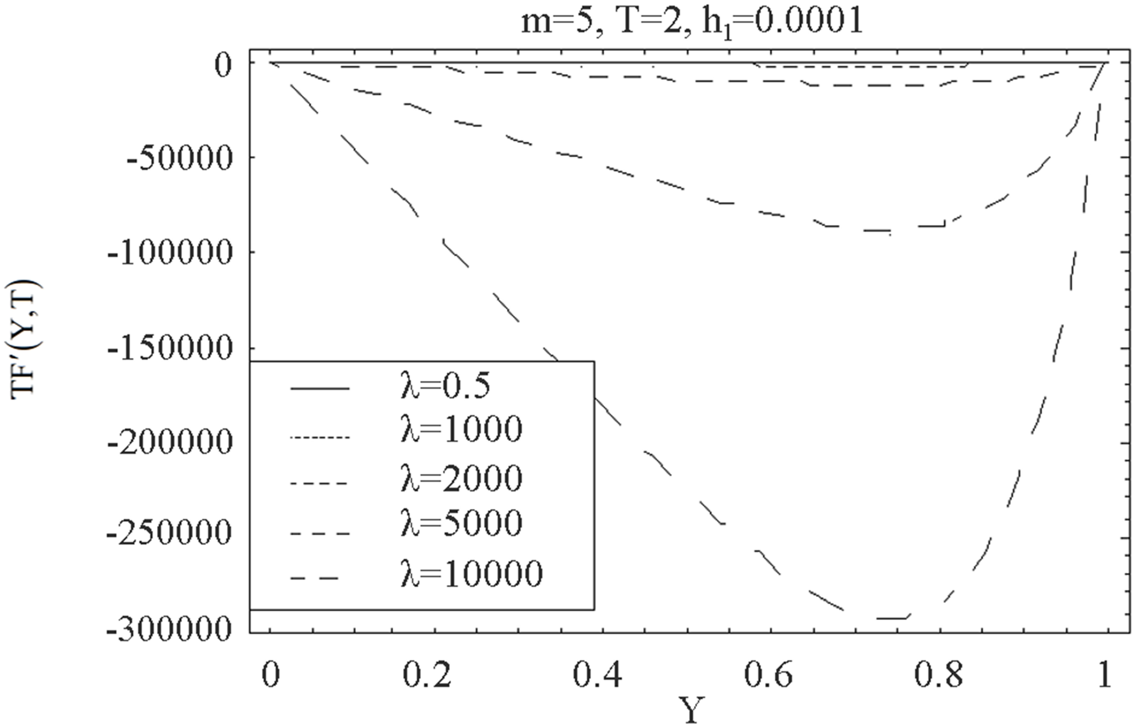
Figure 11. The graph of the horizontal velocity profiles  with
with  for several values of
  and
and .
.

Figure 12. The graph of the horizontal velocity profiles  with
with  for several values of
 , for +ve value of
  and
and .
.
suction  at the top wall, with increase in
 ,
,  increases at all points and the reverse behavior is observed. Figures 14 and 15 describe the variation of the horizontal velocity profiles
  with
with  for several values of time
 , for fixed values of
 ,
,  ,
,  and
and . Figures 14 and 15 are plotted for negative value of
 . From Figure 14 it is observed that for mass injection
  at the bottom wall, with increase in
 , horizontal velocity profiles
  shows increasing trend in magnitude but have negative values. From Fig. 15 it is seen that for mass suction
  at the top wall, with increase in
 ,
,  increases at all points and have positive values, that is, a reverse trend is observed. From the comparison of the Figure 12 to 15 we observe that for positive and negative values of
  the variation of horizontal velocity profiles
  is same. The Figures 8 to 15 shows that mass transfer has a dominant effect on the horizontal velocity profiles
 . We observe from the graphs 8 to 15 that the
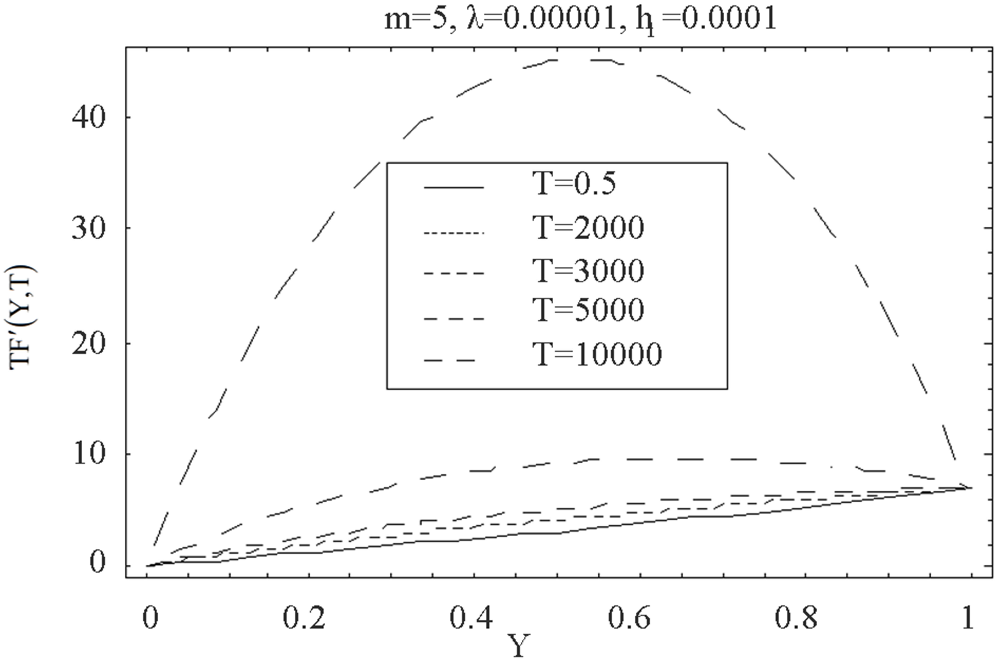
Figure 13. The graph of the horizontal velocity profiles  with
with  for several values of
 , for +ve value of
  and
and .
.

Figure 14. The graph of the horizontal velocity profiles  with
with  for several values of
 , for −ve value of
  and
and .
.
fluid material parameters  and
and  enhance the magnitude of the velocity profile. In Figures 8 to 15 it is observed that the behavior of suction is the reverse of the injection in all the cases, which is a confirmation for the validity of our results. Graphs from 8 to 15 are plotted for large values of the parameter
 ,
,  and
and , because for small values it is observed that the curves of different profiles overlaps and behavior is not clear, whether it is increasing or decreasing.
Figure 16 and 17 elucidate the variation of the shear stress at the wall  with the parameter
  for several values of
 , for fixed values of
 ,
,  and
and . Figure 16 is for mass injection
  at the bottom wall and Figure 17 is for mass suction
  at the top wall. Figure 16 shows that with increase in
 , shear stress at the wall
  increases at all points for all values of
  and have positive values. Figure 17 shows that with increase in
 , shear stress at the wall

Figure 15. The graph of the horizontal velocity profiles  with
with  for several values of
 , for −ve value of
  and
and .
.

Figure 16. The graph of the shear stress at the wall  with
with  for several values of
  and
and .
.
 increases in magnitude for all values of
  but have negative values, inverse behavior is observed. Figures 18 and 19 illustrate the variation of the shear stress at the wall
  with the parameter
  for several values of
 , for fixed values of
 ,
,  and
and . Figure 18 shows that when there is mass injection
  at the bottom wall with increase in
 , shear stress at the wall
  increases and positive for all values of
  From Figure 19 it is observed that for suction at top wall, with increase in
 ,
,  increases in magnitude and have positive and negative values both for all values of
 . Figures 20 and 21 describe the variation of the shear stress at the wall
  with time
  for several values of
 , for fixed values of
 ,
,  and
and . Figure 20 shows that for mass injection
  at the bottom wall, with increase in
 , shear stress at the wall
  increases and positive for all values of time
 . Figure 21
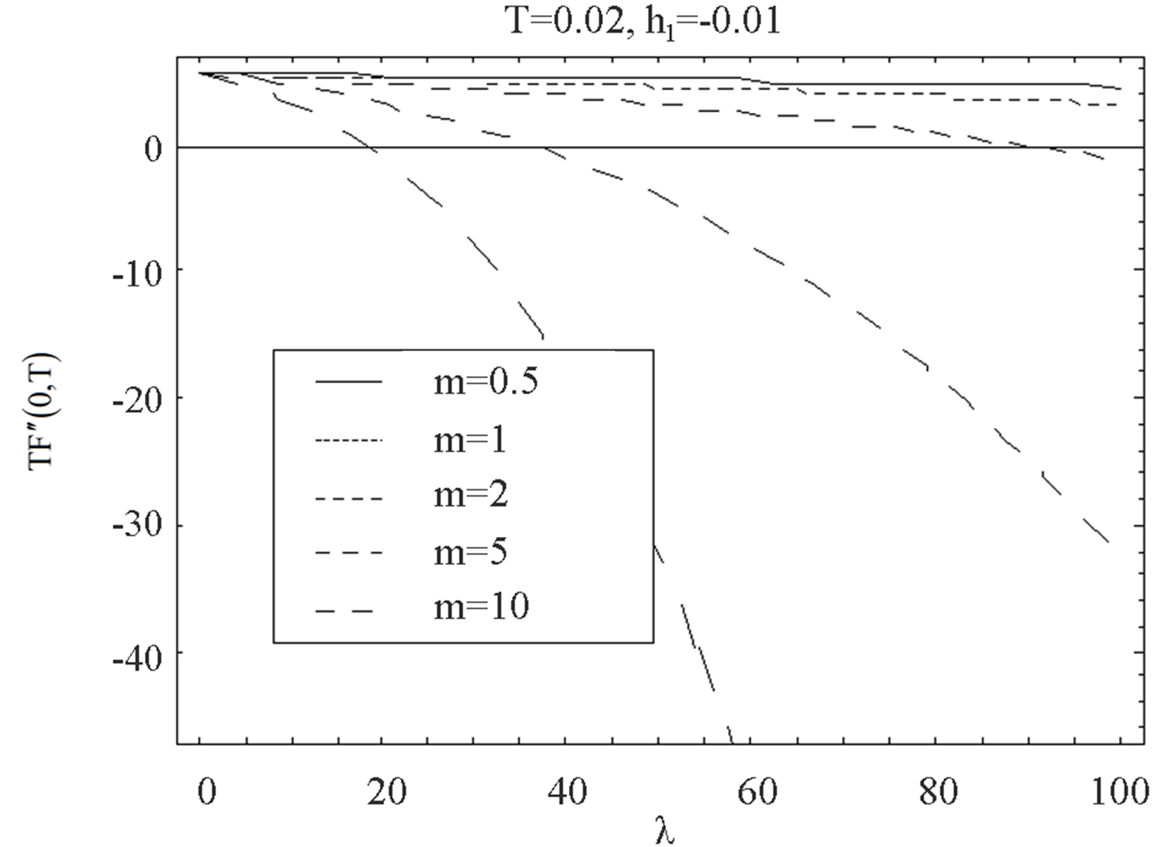
Figure 17. The graph of the shear stress at the wall  with
with  for several values of
  and
and .
.
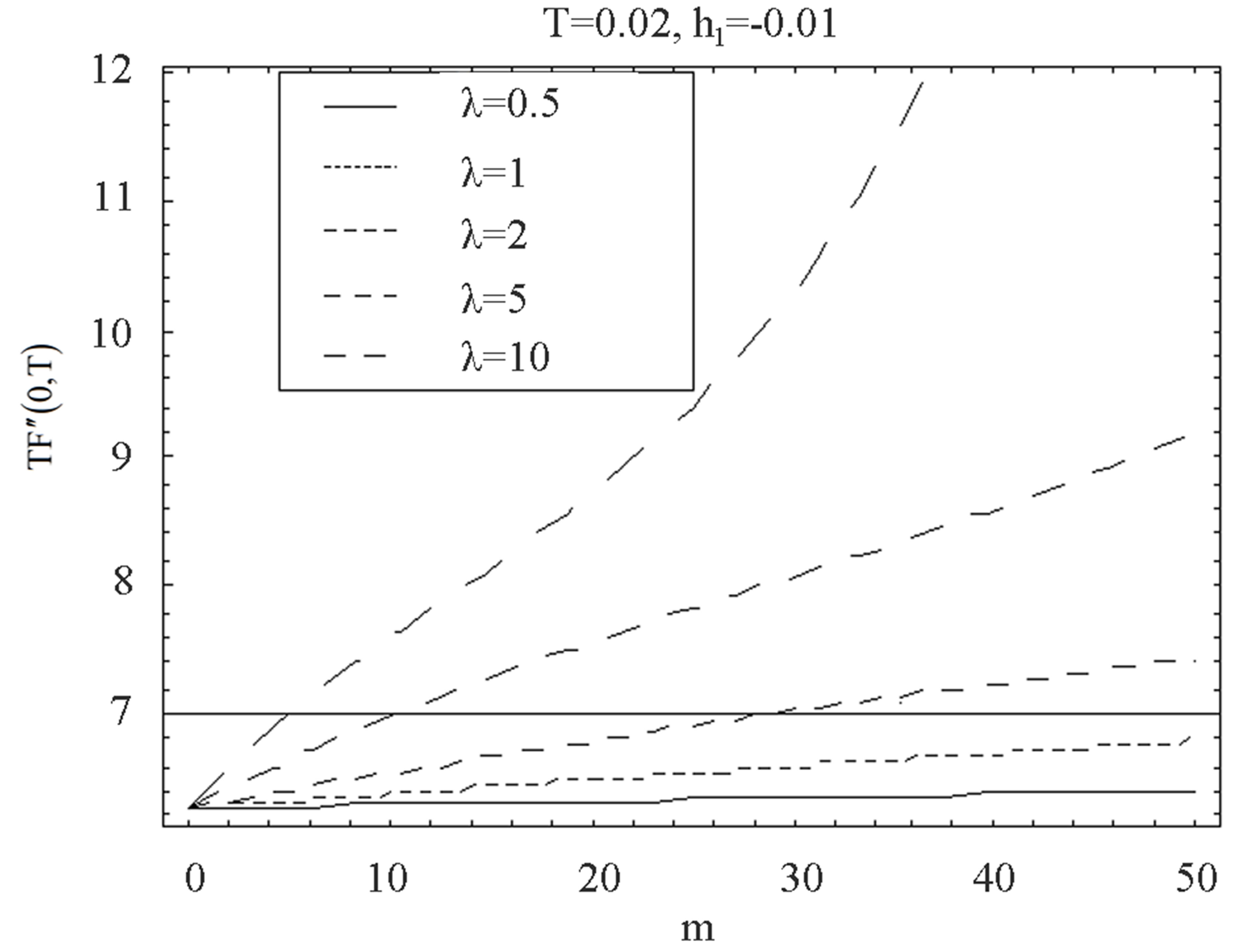
Figure 18. The graph of the shear stress at the wall  with
with  for several values of
  and
and .
.
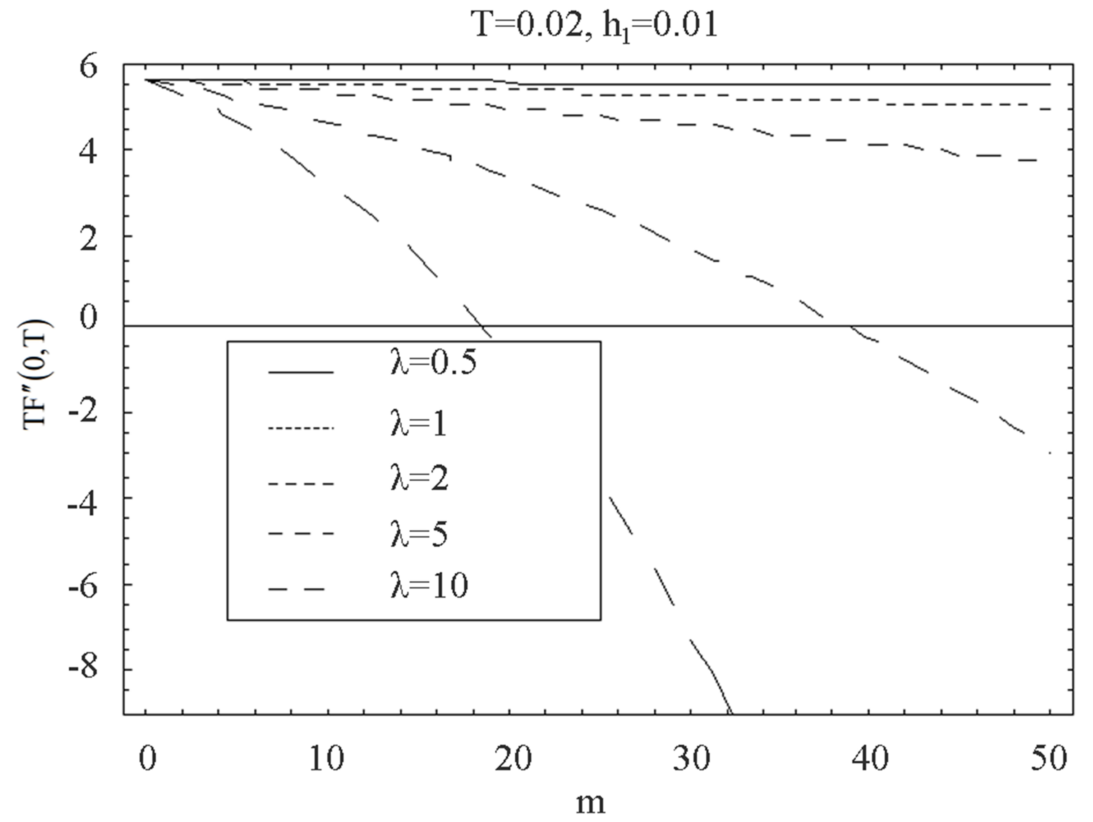
Figure 19. The graph of the shear stress at the wall  with
with  for several values of
  and
and .
.

Figure 20. The graph of the shear stress at the wall  with
with  for several values of
  and
and .
.
shows that for mass suction  at the top wall, with increase in
 ,
,  increases in magnitude and have positive and negative values both for all values of time
 . In Figures 16 to 21 it is observed that shear stress for suction has reverse behavior of injection.
7. Tables
Here Tables 1-2 are prepared for the variation of the initial slopes  and dimensionless shear stress at the wall
 . These results are obtained for different values of
  laying in the interval of convergence, for different order of approximations.
The diagonal Pade approximants can be used to investigate the mathematical behavior of the solution  to determine the initial slope
 . It can be seen from Table 1 that for a fixed value of
 ,
,  ,
,  and
and , with the increase in
 , the initial slope of
  for Pade approximants
 ,
,  and
and  increases.
Figure 21. The graph of the shear stress at the wall  with
with  for several values of
  and
and .
.
For Pade approximants  and
and  initial slope becomes negative and magnitude of the slope decreases with increase in
 .
.
It can be seen from Table 2 that for mass injection  at the bottom wall, for a fixed value of
  and
and , with the increase in
  the shear stress at the wall increases for all values of
 . It is observed that with the increase of mass injection shear stress at the wall also increases. It is also noted that for fixed value of
 ,
,  ,
,  and
and , with the increase in
  shear stress at the wall increases. For all the parameters there is an increase is observed.
8. Conclusions
In this study, a series of solutions for the horizontal velocity field of unsteady incompressible Couette flow with Eyring-Powell model are constructed. The results are discussed under the effects of parameters ,
,  ,
,  and
and  through graphs and tables. We have following observations about the effects of pertinent parameters in the flow field on the horizontal velocity, shear stress at the wall and on initial slope of
 .
.
● The solution series converges in the whole region of  and
and  for
for .
.
● We have considered the general Pade and Taylor approximations of . The polynomials of the rational approximations are given in analytic form.
● We note that the difference between the HAM solution  and Pade approximate solution
  is so small as to be invisible on this scale
 .
.
● We observe that the maximum absolute error for Pade approximant and Taylor approximations occur at the end point .
.
● It is observed that increase in the degree of Taylor polynomial increases the maximum absolute error.
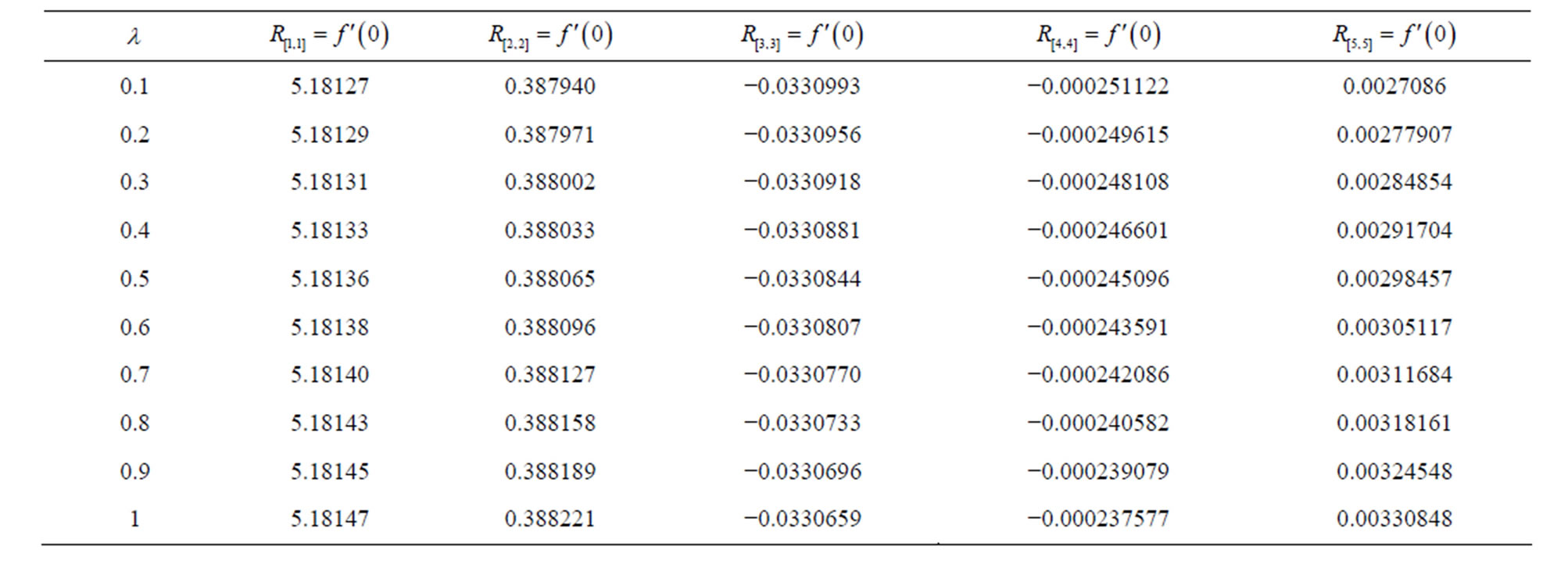
Table 1. Variation of the initial slopes  at
at ,
,  ,
,  and
and  for various values of
 .
.
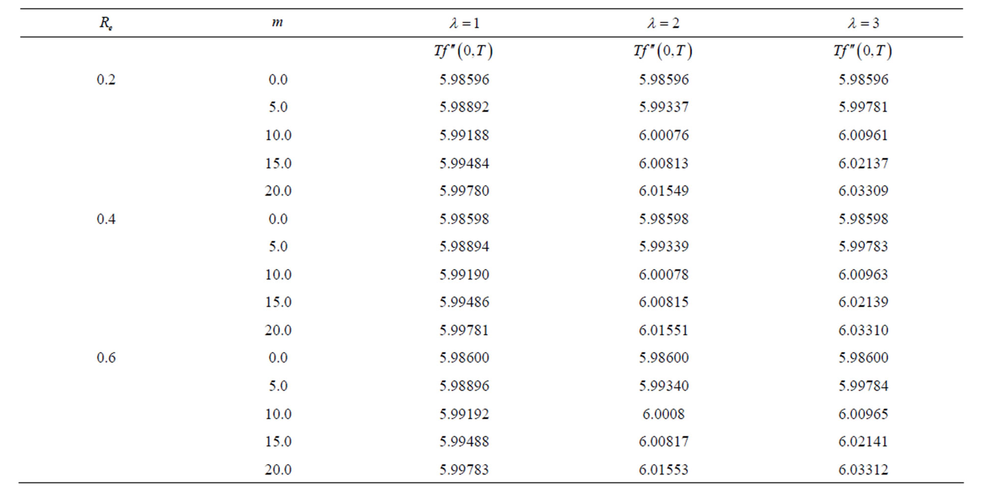
Table 2. Variation of the dimensionless shear stress at the wall  at
at  and
and .
.
● For positive and negative values of local non-Newtonian parameter , the variation of the horizontal velocity profiles is same.
● The fluid material parameters  and
and  enhance the magnitude of the velocity profile.
● It is noted that the mass transfer has a dominant effect on the velocity profile and in all cases behavior of suction is the reverse of the injection.
● The curves of the velocity profile for small values of ,
,  and
and  overlaps and behavior is not explainable.
● For mass suction and injection at the bottom and top wall shear, stress at the wall increases in all cases but has opposite sign.
Initial slope of  for Pade approximants
 ,
,
 ,
,  increases and for
 ,
,  it decreases with increase in
 .
.
REFERENCES
- T. Hayat, M. Khan, A. M. Siddiqui and S. Asghar, “Transient Flows of a Second Grade Fluid,” International Journal of Non-Linear Mechanics, Vol. 39, No. 10, 2004, pp. 1621-1633. http://dx.doi.org/10.1016/j.ijnonlinmec.2002.12.001
- T. Hayat, Z. Abbas and M. Sajid, “Heat and Mass Transfer Analysis on the Flow of a Second Grade Fluid in the Presence of Chemical Reaction,” Physics Letters A, Vol. 372, No. 14, 2008, pp. 2004-2408. http://dx.doi.org/10.1016/j.physleta.2007.10.102
- T. Hayat, R. Ellahi and F. M. Mahomed, “Exact Solution of a Thin Film Flow of an Oldroyd 6-Constant Fluid over a Moving Belt,” Communications in Nonlinear Science and Numerical Simulation, Vol. 14, No. 1, 2009, pp. 133- 139. http://dx.doi.org/10.1016/j.cnsns.2007.08.001
- T. Hayat, R. Ellahi and F. M. Mahomed, “Exact Solutions for Thin Film Flow of a Third Grade Fluid Down an Inclined Plane,” Chaos, Solitons & Fractals, Vol. 38, No. 5, 2008, pp. 1336-1341. http://dx.doi.org/10.1016/j.chaos.2008.03.006
- T. Hayat, T. Javed and Z. Abbas, “MHD Flow of a Micropolar Fluid near a Stagnation Point towards a NonLinear Stretching Surface,” Nonlinear Analysis: Real World Applications, Vol. 10, No. 3, 2009, pp. 1514-1526. http://dx.doi.org/10.1016/j.nonrwa.2008.01.019
- S. Asghar, M. Khan and T. Hayat, “Magnetohydrodynamic Transient Flows of a Non-Newtonian Fluid,” International Journal of Non-Linear Mechanics, Vol. 40, No. 5, 2005, pp. 589-601. http://dx.doi.org/10.1016/j.ijnonlinmec.2004.07.011
- M. Khan, Z. Abbas and T. Hayat, “Analytic Solution for Flow of Sisko Fluid through a Porous Medium,” Transport in Porous Media, Vol. 71, No. 1, 2008, pp. 23-37 http://dx.doi.org/10.1007/s11242-007-9109-4
- M. Khan, S. Hyder Ali, T. Hayat and C. Fetecau, “MHD Flows of a Second Grade Fluid between Two Side Walls Perpendicular to a Plate through a Porous Medium,” International Journal of Non-Linear Mechanics, Vol. 43, No. 4, 2008, pp. 302-319. http://dx.doi.org/10.1016/j.ijnonlinmec.2007.12.016
- R. Cortell, “A Note on Flow and Heat Transfer of a Viscoelastic Fluid over a Stretching Sheet,” International Journal of Non-Linear Mechanics, Vol. 41, No. 1, 2006, pp. 78-85. http://dx.doi.org/10.1016/j.ijnonlinmec.2005.04.008
- R. Cortell, “MHD Flow and Mass Transfer of an Electrically Conducting Fluid of Second Grade in a Porous Medium over a Stretching Sheet with Chemically Reactive Species,” Chemical Engineering and Processing: Process Intensification, Vol. 46, No. 8, 2007, pp. 721-728. http://dx.doi.org/10.1016/j.cep.2006.09.008
- M. Ayub, H. Zaman, M. Sajid and T. Hayat, “Analytical Solution of Stagnation-Point Flow of a Viscoelastic Fluid towards a Stretching Surface,” Communications in Nonlinear Science and Numerical Simulation, Vol. 13, No. 9, 2008, pp.1822-1835. http://dx.doi.org/10.1016/j.cnsns.2007.04.021
- M. Ayub, H. Zaman and M. Ahmad, “Series Solution of Hydromagnetic Flow and Heat Transfer with Hall Effect in a Second Grade Fluid over a Stretching Sheet,” Central European Journal of Physics, Vol. 8, No. 1, 2010, pp. 135-149. http://dx.doi.org/10.2478/s11534-009-0110-0
- M. Ayub and H. Zaman, “Analytical Solution of Orthogonal Flow Impinging on a Wall with Suction or Blowing,” Journal of Basic and Applied Sciences, Vol. 6, No. 2, 2010, pp. 93-97.
- P. D. Ariel, T. Hayat and S. Asghar, “The Flow of an Elastico-Viscous Fluid Past a Stretching Sheet with Partial Slip,” Acta Mechanica, Vol. 187, No. 1-4, 2006, pp. 29-35. http://dx.doi.org/10.1007/s00707-006-0370-3
- K. R. Rajagopal, “A Note on Unsteady Unidirectional Flows of a Non-Newtonian Fluid,” International Journal of Non-Linear Mechanics, Vol. 17, No. 5-6, 1982, pp. 369-373. http://dx.doi.org/10.1016/0020-7462(82)90006-3
- K. R. Rajagopal, “On the Creeping Flow of the SecondOrder Fluid,” International Journal of Non-Linear Mechanics, Vol. 15, No. 2, 1984, pp. 239-246. http://dx.doi.org/10.1016/0377-0257(84)80008-7
- K. R. Rajagopal and T. Y. Na, “On Stoke’s Problem for a Non-Newtonian Fluid,” Acta Mechanica, Vol. 48, No. 3-4, 1983, pp. 233-239. http://dx.doi.org/10.1007/BF01170422
- M. E. Erdogan, “Plane Surface Suddenly Set in Motion in a Non-Newtonian Fluid,” Acta Mechanica, Vol. 108, No. 1-4, 1995, pp. 179-187. http://dx.doi.org/10.1007/BF01177337
- A. M. Siddiqui and P. N. Kaloni, “Certain Inverse Solutions of a Non-Newtonian Fluid,” International Journal of Non-Linear Mechanics, Vol. 21, No. 6, 1986, pp. 459- 473. http://dx.doi.org/10.1016/0020-7462(86)90042-9
- C. Fetecau, “Cone and Plate Flow of a Second Grade,” Acta Mechanica, Vol. 122, No. 1-4, 1977, pp. 225-230.
- T. Fang, “A Note on the Incompressible Couette Flow with Porous Walls,” International Communications in Heat and Mass Transfer, Vol. 31, No. 1, 2004, pp. 31-41. http://dx.doi.org/10.1016/S0735-1933(03)00199-4
- A. R. A. Khaled and K. Vafai, “The Effect of the Slip Condition on Stokes and Couette Flows due to an Oscillating Wall: Exact Solutions,” International Journal of Non-Linear Mechanics, Vol. 39, No. 5, 2004, pp. 795-809. http://dx.doi.org/10.1016/S0020-7462(03)00043-X
- S. Asghar, T. Hayat and P. D. Ariel, “Unsteady Couette Flows in a Second Grade Fluid with Variable Material Properties,” Communications in Nonlinear Science and Numerical Simulation, Vol. 14, No. 1, 2009, pp. 154-159. http://dx.doi.org/10.1016/j.cnsns.2007.07.016
- T. Hayat, E. Momoniat and F. M. Mahomed, “Axial Couette Flow of an Electrically Conducting Fluid in an Annulus,” International Journal of Modern Physics B, Vol. 22, No. 15, 2008, pp. 2489-2500. http://dx.doi.org/10.1142/S0217979208039587
- T. Hayat and A. H. Kara, “Couette Flow of a Third-Grade Fluid with Variable Magnetic Field,” Mathematical and Computer Modelling, Vol. 43, No. 1-2, 2006, pp. 132-137
- G. S. Seth, Md. S. Ansari and R. Nandkeolyar, “Effects of Rotation and Magnetic Field on Unsteady Couette Flow in a Porous Channel,” Journal of Applied Fluid Mechanics, Vol. 4, No. 2, 2011, pp. 95-103.
- R. Bhaskara and N. D. Bathaiah, “Halll Effects on MHD Couette Flow through a Porous Straight Channel,” Defense Science Journal, Vol. 32, No. 4, 1982, pp. 313-326.
- S. Das, S. L. Maji, M. Guria and R. N. Jana, “Unsteady MHD Couette Flow in a Rotating System,” Mathematical and Computer Modelling, Vol. 50, No. 7-8, 2009, pp. 1211-1217. http://dx.doi.org/10.1016/j.mcm.2009.05.036
- R. Ganapathy, “A Note on Oscillatory Couette Flow in a Rotating System,” ASME Journal of Applied Mechanics, Vol. 61, No. 1, 1994, pp. 208-209. http://dx.doi.org/10.1115/1.2901403
- M. Guria, R. N. Jana and S. K. Ghosh, “Unsteady Couette Flow in A Rotating System,” International Journal of Non-Linear Mechanics, Vol. 41, No. 6-7, 2006, pp. 838- 843. http://dx.doi.org/10.1016/j.ijnonlinmec.2006.04.010
- M. Guria, S. Das, R. N. Jana and S. K. Ghosh, “Oscillatory Couette Flow in the Presence of an Inclined Magnetic Field,” Meccanica, Vol. 44, No. 5, 2009, pp. 555- 564. http://dx.doi.org/10.1007/s11012-009-9195-1
- K. D. Singh, M. G. Gorla and H. Raj, “A Periodic Solution of Oscillatory Couette Flow through Porous Medium in Rotating System,” Indian Journal of Pure and Applied Mathematics, Vol. 36, 2005, pp. 151-159.
- R. E. Powell and H. Eyring, “Mechanism for the Relaxation Theory of Viscosity,” Nature, Vol. 154, No. 55, 1944, pp. 427-428.
- N. T. M. Eldabe, A. A. Hassan and M. A. A. Mohamed, “Effects of Couple Stresses on the MHD of a Non-Newtonian Unsteady Flow between Two Parallel Porous Plates,” Zeitschrift für Naturforschung, Vol. 58, No. 2, 2003, pp. 204-210.
- J. Zueco and O. A. Beg, “Network Numerical Simulation Applied to Pulsatile Non-Newtonian Flow through a Channel with Couple Stress and Wall Mass Flux Effects,” International Journal of Applied Mathematics and Mechanics, Vol. 5, 2009, pp. 1-16.
- K. V. Prasad, P. S. Datti and B. T. Raju, “Momentum and Heat Transfer of a Non-Newtonian Eyring-Powell Fluid over a Non-Isothermal Stretching Sheet,” International Journal of Mathematical Archive, Vol. 4, No. 1, 2013, pp. 230-241.
- M. Patel and M. G. Timol, “Numerical Treatment of MHD Powell-Eyring Fluid Flow Using the Method of Satisfaction of Asymptotic Boundary Conditions,” International Journal of Computer Science, Vol. 1, No. 2, 2011, pp. 71- 78.
- V. Sirohi, M. G. Timol and N. I. Kalathia, “Numerical Treatment of Powell-Eyring Fluid Flow past a 90˚ Wedge,” Reg Journal of Heat and Mass Transfer, Vol. 6, No. 3, 1984, pp. 219-223.
- T. Javed, N. Ali, Z. Abbas and M. Sajid, “Flow of an Eyring-Powell Non-Newtonian Fluid over a Stretching Sheet,” Chemical Engineering Communications, Vol. 200, 2013, pp. 327-336. http://dx.doi.org/10.1080/00986445.2012.703151
- S. Noreen and M. Qasim, “Peristaltic Flow of MHD Eyring-Powell Fluid in a Channel,” The European Physical Journal Plus, Vol. 128, No. 8, 2013, pp. 91-103. http://dx.doi.org/10.1140/epjp/i2013-13091-3
- S. J. Liao, “Notes on the Homotopy Analysis Method: Some Definitions and Theorems,” Communications in Nonlinear Science and Numerical Simulation, Vol. 14, No. 4, 2009, pp. 983-997
- S. J. Liao, J. Su and A. T. Chwang, “Series Solution for a Nonlinear Model of Combined Convective and Radiative Cooling of a Spherical Body,” International Journal of Heat and Mass Transfer, Vol. 49, No. 15-16, 2006, pp. 2437-2445 http://dx.doi.org/10.1016/j.ijheatmasstransfer.2006.01.030
- S. J. Liao, “An Analytic Solution of Unsteady BoundaryLayer Flows Caused by an Impulsively Stretching Plate,” Communications in Nonlinear Science and Numerical Simulation, Vol. 11, No. 3, 2006, pp. 326-339.
- S. J. Liao, “On the Homotopy Analysis Method for Nonlinear Problems,” Applied Mathematics and Computation, Vol. 147, No. 2, 2004, pp. 499-513.
- S. J. Liao, “An Analytic Approximate Technique for Free Oscillations of Positively Damped Systems with Algebraically Decaying Amplitude,” International Journal of Non-Linear Mechanics, Vol. 38, No. 8, 2003, pp. 1173- 1183. http://dx.doi.org/10.1016/S0020-7462(02)00062-8
- S. J. Liao and A. Campo, “Analytic Solutions of the Temperature Distribution in Blasius Viscous Flow Problems,” Journal of Fluid Mechanics, Vol. 453, 2002, pp. 411-425. http://dx.doi.org/10.1017/S0022112001007169
- S. J. Liao, “An Analytic Approximation of the Drag Coefficient for the Viscous Flow past a Sphere,” International Journal of Non-Linear Mechanics, Vol. 37, No. 1, 2002, pp. 1-18. http://dx.doi.org/10.1016/S0020-7462(00)00092-5
- S. J. Liao, “An Explicit, Totally Analytic Approximate Solution for Blasius’ Viscous Flow Problems,” International Journal of Non-Linear Mechanics, Vol. 34, No. 4, 1999, pp. 759-778. http://dx.doi.org/10.1016/S0020-7462(98)00056-0
- S. J. Liao, “The Proposed Homotopy Analysis Technique for the Solution of Nonlinear Problem,” Ph.D. Thesis, Shanghai Jiao Tong University, Shanghai, 1992.
- S. Abbasbandy, T. Hayat, R. Ellahi and S. Asghar, “Numerical Results of Flow in a Third Grade Fluid between Two Porous Walls,” Zeitschrift Fur Naturforschung A, Vol. 64a, 2009, pp. 59-64.
- S. Abbasbandy and F. S. Zakaria, “Soliton Solution for the Fifth-Order Kdv Equation with the Homotopy Analysis Method,” Nonlinear Dynamics, Vol. 51, No. 1-2, 2008, pp. 83-87. http://dx.doi.org/10.1007/s11071-006-9193-y
- S. Abbasbandy, “Approximate Solution of the Nonlinear Model of Diffusion and Reaction Catalysts by Means of the Homotopy Analysis Method,” Chemical Engineering Journal, Vol. 136, No. 2-3, 2008, pp. 144-150. http://dx.doi.org/10.1016/j.cej.2007.03.022
- S. Abbasbandy, “The Application of Homotopy Analysis Method to Solve a Generalized Hirota-Satsuma Coupled KdV Equation,” Physics Letters A, Vol. 361, No. 6, 2007, pp. 478-483. http://dx.doi.org/10.1016/j.physleta.2006.09.105
- S. Abbasbandy, “Homotopy Analysis Method for Heat Radiation Equations,” International Communications in Heat and Mass Transfer, Vol. 34, No. 3, 2007, pp. 380- 387. http://dx.doi.org/10.1016/j.icheatmasstransfer.2006.12.001
- S. Abbasbandy, “The Application of Homotopy Analysis Method to Nonlinear Equations Arising in Heat Transfer,” Physics Letters A, Vol. 360, No. 1, 2006, pp. 109- 113. http://dx.doi.org/10.1016/j.physleta.2006.07.065
- H. Zaman and M. Ayub, “Series Solution of Unsteady Free Convection Flow with Mass Transfer along an Accelerated Vertical Porous Plate with Suction,” Central European Journal of Physics, Vol. 8, No. 6, 2010, pp. 931-939. http://dx.doi.org/10.2478/s11534-010-0007-y
- H. Zaman, T. Hayat, M. Ayub and R. S. R. Gorla, “Series Solution for Heat Transfer from a Continuous Surface in a Parallel Free Stream of Viscoelastic Fluid,” Numerical Methods for Partial Differential Equations, Vol. 27, No. 6, 2011, pp. 1511-1524. http://dx.doi.org/10.1002/num.20593
- T. Hayat, H. Zaman and M. Ayub, “Analytic Solution of Hydromagnetic Flow with Hall Effect over a Surface Stretching with a Power Law Velocity,” Numerical Methods for Partial Differential Equations, Vol. 27, No. 4, 2010, pp. 937-959. http://dx.doi.org/10.1002/num.20562
- J. H. Mathews and K. D. Fink, “Numerical Methods Using MATLAB,” Printice-Hall Inc., Upper Saddle River, 2004.
- F. Labropulu and O. P. Chandna, “Oblique Flow Impinging on a Wall with Suction or Blowing,” Acta Mechanica, Vol. 115, No. 1-4, 1996, pp. 15-25. http://dx.doi.org/10.1007/BF01187425
- F. Ahmad and W. H. Albarakati, “An Approximate Analytic Solution of the Blasius Problem,” Communications in Nonlinear Science and Numerical Simulation, Vol. 14, 2008, pp. 1021-1024.