Paper Menu >>
Journal Menu >>
 Int. J. Communications, Network and System Sciences, 2011, 4, 464-467 doi:10.4236/ijcns.2011.47056 Published Online July 2011 (http://www.SciRP.org/journal/ijcns) Copyright © 2011 SciRes. IJCNS Effects of Antenna Tilting on Transmitting Power in Mobile Cellular Communication Systems Gbenga E. Aderibigbe, Michael O. Kolawole, Victor S. A. Adeloye Department of Electrical and Electronics Engineering, School of Engineering and Engineering Technology, Federal University of Technology, Akure, Nigeria E-mail: adescuro@yahoo.com Received August 1, 2009; revised October 6, 2010; accepted March 24, 2011 Abstract Radio resources must be wisely managed, in wireless communication systems, when implementing different multiple access techniques. This perspective is pivotal since the variations in propagation channel are very fast and the system is highly complex due to random and unpredictable movement of mobile users continu- ously. The complexity in the cellular system periodically contributes to different interference levels, high or low, resulting in the degradation of the system capacity. Transmitter power control is an efficient technique to mitigate the effect of interference under fading conditions, combat the Near-Far problem and conserve the battery life. Several remedial measures—like space diversity, frequency diversity, route diversity, increase in antenna height, antenna tilting, etc.—have been tried by many operators to overcome the debilitating effect of multipath fading in fixed line-of-sight microwave and mobile communication links. Among these reme- dial measures, diversity techniques have been extensively studied in terms of improvement factor, whereas the concept of antenna tilting is relatively less explored compared with other remedial measures. In this study, the effect of antenna tilting on fixed and mobile communication links is investigated to find out the optimum tilting angles in terms of design parameters, as well as on quality of service (QoS). The paper established that a deviation of more than 1.5˚ in antenna elevation angle would impact on QoS requirements and seriously affect the quality of signal to be received by the mobile systems. Keywords: Optimum Tilting Angle, QoS, Near-Far Effect, Mobile Station, Carrier-to-Interference Ratio 1. Introduction Antenna beam tilting effects have been effectively em- ployed in the past to overcome multipath fading induced by super refractive or ducting layers in microwave fixed line-of-sight (LOS) links. These approaches and experi- ments helped to design angle diversity schemes in LOS links. In these cases, upward tilting of the antenna cuts- off or reduces the radio frequency energy refracted by the ground-based layers and reduces the multipath fading [1-3]. Taking the clue from these experiments, some ope- rators have tried to employ the concept of tilting on mo- bile communications in cellular networks. It has been observed that downward tilting of antenna beam can re- duce the interference effects in other macro cells. Since atmospheric super-refractive and ducting layers would not affect the performance of cellular networks, upward tilting of antenna beam cannot yield appreciable impro- vements, except in special situations [4]. Downward tilt- ing decreases the probability of occurrence of unaccept- able inter symbol interference (ISI) due to multipath propagation by diminishing the power level of echoes with long delay times. Delay time determines the root- mean-square (rms) delay spread, which in turn deter- mines the transmissible bit rate. In analogue systems, fade depth can be decreased. However, in mobile com- munications, when the cell site uses a high gain antenna, downward tilting can direct the nulls in the antenna pat- tern towards the horizon to prevent the energy from propagating into other cells. In the case of a low-gain antenna, discrimination between horizon and edge of a cell is less. This can be improved with increase in height. Using a high gain, high antenna elevation and downward tilting, the base-station can reduce its power relative to what would be required from a low-elevation site. When the antenna height is close to that of buildings, any height increase would degrade the delay spread due to long distance reflectors. It seems that high sites and 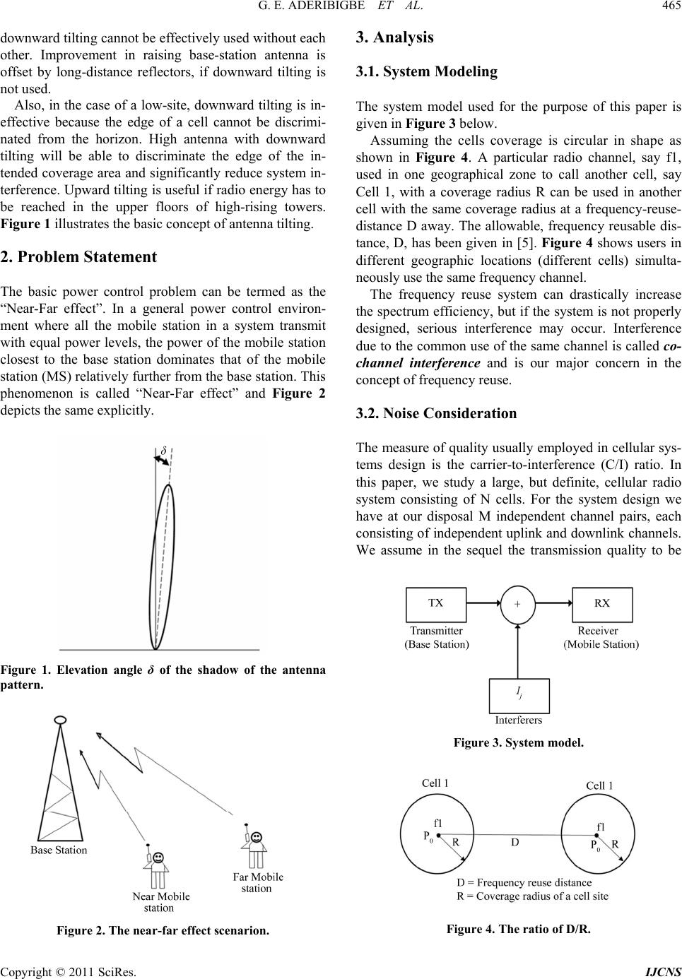 G. E. ADERIBIGBE ET AL. Copyright © 2011 SciRes. IJCNS 465 downward tilting cannot be effectively used without each other. Improvement in raising base-station antenna is offset by long-distance reflectors, if downward tilting is not used. Also, in the case of a low-site, downward tilting is in- effective because the edge of a cell cannot be discrimi- nated from the horizon. High antenna with downward tilting will be able to discriminate the edge of the in- tended coverage area and significantly reduce system in- terference. Upward tilting is useful if radio energy has to be reached in the upper floors of high-rising towers. Figure 1 illustrates the basic concept of antenna tilting. 2. Problem Statement The basic power control problem can be termed as the “Near-Far effect”. In a general power control environ- ment where all the mobile station in a system transmit with equal power levels, the power of the mobile station closest to the base station dominates that of the mobile station (MS) relatively further from the base station. This phenomenon is called “Near-Far effect” and Figure 2 depicts the same explicitly. Figure 1. Elevation angle δ of the shadow of the antenna pattern. Figure 2. The near-far effect scenarion. 3. Analysis 3.1. System Modeling The system model used for the purpose of this paper is given in Figure 3 below. Assuming the cells coverage is circular in shape as shown in Figure 4. A particular radio channel, say f1, used in one geographical zone to call another cell, say Cell 1, with a coverage radius R can be used in another cell with the same coverage radius at a frequency-reuse- distance D away. The allowable, frequency reusable dis- tance, D, has been given in [5]. Figure 4 shows users in different geographic locations (different cells) simulta- neously use the same frequency channel. The frequency reuse system can drastically increase the spectrum efficiency, but if the system is not properly designed, serious interference may occur. Interference due to the common use of the same channel is called co- channel interference and is our major concern in the concept of frequency reuse. 3.2. Noise Consideration The measure of quality usually employed in cellular sys- tems design is the carrier-to-interference (C/I) ratio. In this paper, we study a large, but definite, cellular radio system consisting of N cells. For the system design we have at our disposal M independent channel pairs, each consisting of independent uplink and downlink channels. We assume in the sequel the transmission quality to be Figure 3. System model. Figure 4. The ratio of D/R. 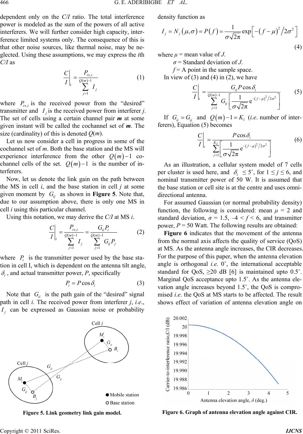 G. E. ADERIBIGBE ET AL. Copyright © 2011 SciRes. IJCNS 466 dependent only on the C/I ratio. The total interference power is modeled as the sum of the powers of all active interferers. We will further consider high capacity, inter- ference limited systems only. The consequence of this is that other noise sources, like thermal noise, may be ne- glected. Using these assumptions, we may express the ith C/I as , 1 1 rx i Qm i j j P C I I (1) where ,rx i Pis the received power from the “desired” transmitter and j I is the received power from interferer j. The set of cells using a certain channel pair m at some given instant will be called the cochannel set of m. The size (cardinality) of this is denoted Q(m). Let us now consider a cell in progress in some of the cochannel set of m. Both the base station and the MS will experience interference from the other 1Qm co- channel cells of the set. 1Qm is the number of in- terferers. Now, let us denote the link gain on the path between the MS in cell i, and the base station in cell j at some given moment by ij G as shown in Figure 5. Note that, due to our assumption above, there is only one MS in cell i using this particular channel. Using this notation, we may derive the C/I at MS i. , 11 11 rx iii i Qm Qm i j ij j jj PGP C I I GP (2) where i P is the transmitter power used by the base sta- tion in cell I, which is dependent on the antenna tilt angle, i , and actual transmitter power, P, specifically cos ii PP (3) Note that ii G is the path gain of the “desired” signal path in cell i. The received power from interferer j, i.e., j I can be expressed as Gaussian noise or probability Figure 5. Link geometry link gain model. density function as 22 1 ,exp2 2π jj IN Pff (4) where μ = mean value of J. σ = Standard deviation of J. f = A point in the sample space. In view of (3) and (4) in (2), we have 22 1 2 1 cos 1e 2π ii i Qm f i ij j GP C IG (5) If ii ij GG and 1l Qm K (i.e. number of inter- ferers), Equation (5) becomes 22 2 1 cos 1e 2π I i K f i j P C I (6) As an illustration, a cellular system model of 7 cells per cluster is used here, and i ≤ 5˚, for 1 ≤ j ≤ 6, and nominal transmitter power of 50 W. It is assumed that the base station or cell site is at the centre and uses omni- directional antenna. For assumed Gaussian (or normal probability density) function, the following is considered: mean μ = 2 and standard deviation, σ = 1.5, –4 < f < 6, and transmitter power, P = 50 Watt. The following results are obtained: Figure 6 indicates that the movement of the antenna from the normal axis affects the quality of service (QoS) at MS. As the antenna angle increases, the CIR decreases. For the purpose of this paper, when the antenna elevation angle is orthogonal i.e. 0˚, the international acceptable standard for QoS, ≥20 dB [6] is maintained upto 0.5˚. Marginal QoS acceptance upto 1.5˚. As the antenna ele- vation angle increases beyond 1.5˚, the QoS is compro- mised i.e. the QoS at MS starts to be affected. The result shows effect of variation of antenna elevation angle on Figure 6. Graph of antenna elevation angle against CIR. 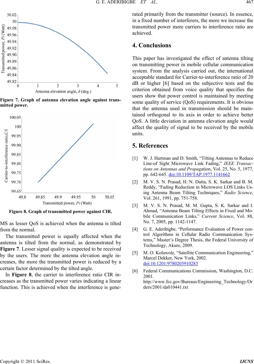 G. E. ADERIBIGBE ET AL. Copyright © 2011 SciRes. IJCNS 467 Figure 7. Graph of antenna elevation angle against trans- mitted power. Figure 8. Graph of transmitted power against CIR. MS as lesser QoS is achieved when the antenna is tilted from the normal. The transmitted power is equally affected when the antenna is tilted from the normal, as demonstrated by Figure 7. Lesser signal quality is expected to be received by the users. The more the antenna elevation angle in- creases, the more the transmitted power is reduced by a certain factor determined by the tilted angle. In Figure 8, the carrier to interference ratio CIR in- creases as the transmitted power varies indicating a linear function. This is achieved when the interference is gene- rated primarily from the transmitter (source). In essence, in a fixed number of interferers, the more we increase the transmitted power more carriers to interference ratio are achieved. 4. Conclusions This paper has investigated the effect of antenna tilting on transmitting power in mobile cellular communication system. From the analysis carried out, the international acceptable standard for Carrier-to-interference ratio of 20 dB or higher [6] based on the subjective tests and the criterion obtained from voice quality that specifies the users show that power control is maintained by meeting some quality of service (QoS) requirements. It is obvious that the antenna used in transmission should be main- tained orthogonal to its axis in order to achieve better QoS. A little deviation in antenna elevation angle would affect the quality of signal to be received by the mobile units. 5. References [1] W. J. Hartman and D. Smith, “Tilting Antennas to Reduce Line-of Sight Microwave Link Fading,” IEEE Transac- tions on Antennas and Propagation, Vol. 25, No. 5, 1977, pp. 642-645. doi:10.1109/TAP.1977.1141662 [2] M. V. S. N. Prasad, H. N. Dutta, S. K. Sarkar and B. M. Reddy, “Fading Reduction in Microwave LOS Links Us- ing Antenna Beam Tilting Techniques,” Radio Science, Vol. 261, 1991, pp. 751-758. [3] M. V. S. N. Prasad, M. M. Gupta, S. K. Sarkar and I. Ahmad, “Antenna Beam Tilting Effects in Fixed and Mo- bile Communication Links,” Current Science, Vol. 88, No. 7, 2005, pp. 1142-1147. [4] G. E. Aderibigbe, “Performance Evaluation of Power con- trol Algorithms in Cellular Radio Communication Sys- tems,” Master’s Degree Thesis, the Federal University of Technology, Akure, 2009. [5] M. O. Kolawole, “Satellite Communication Engineering,” Marcel Dekker, New York, 2002. doi:10.1201/9780203910283 [6] Federal Communications Commission, Washington, D.C. 2001. http://www.fcc.gov/Bureaus/Engineering_Technology/Or ders/2001/da010441.txt |