Paper Menu >>
Journal Menu >>
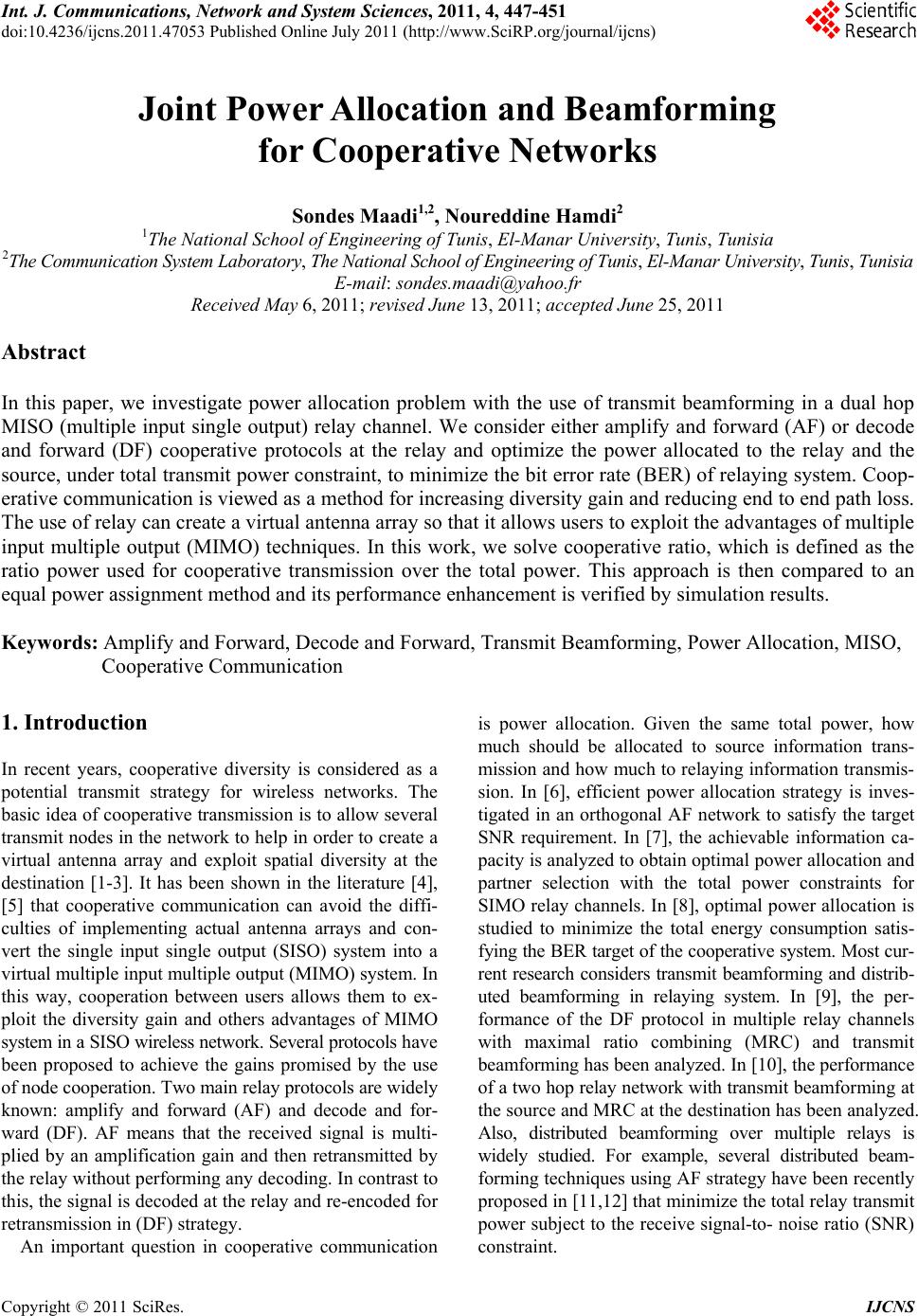 Int. J. Communications, Network and System Sciences, 2011, 4, 447-451 doi:10.4236/ijcns.2011.47053 Published Online July 2011 (http://www.SciRP.org/journal/ijcns) Copyright © 2011 SciRes. IJCNS Joint Power Allocation and Beamforming for Cooperative Networks Sondes Maadi1,2, Noureddine Hamdi2 1The National School of Engineering of Tunis, El-Manar University, Tunis, Tunisia 2The Communication System Laboratory, The National School of Engineering of Tunis, El-Manar University, Tunis, Tunisia E-mail: sondes.maadi@yahoo.fr Received May 6, 2011; revised June 13, 2011; accepted June 25, 2011 Abstract In this paper, we investigate power allocation problem with the use of transmit beamforming in a dual hop MISO (multiple input single output) relay channel. We consider either amplify and forward (AF) or decode and forward (DF) cooperative protocols at the relay and optimize the power allocated to the relay and the source, under total transmit power constraint, to minimize the bit error rate (BER) of relaying system. Coop- erative communication is viewed as a method for increasing diversity gain and reducing end to end path loss. The use of relay can create a virtual antenna array so that it allows users to exploit the advantages of multiple input multiple output (MIMO) techniques. In this work, we solve cooperative ratio, which is defined as the ratio power used for cooperative transmission over the total power. This approach is then compared to an equal power assignment method and its performance enhancement is verified by simulation results. Keywords: Amplify and Forward, Decode and Forward, Transmit Beamforming, Power Allocation, MISO, Cooperative Communication 1. Introduction In recent years, cooperative diversity is considered as a potential transmit strategy for wireless networks. The basic idea of cooperative transmission is to allow several transmit nodes in the network to help in order to create a virtual antenna array and exploit spatial diversity at the destination [1-3]. It has been shown in the literature [4], [5] that cooperative communication can avoid the diffi- culties of implementing actual antenna arrays and con- vert the single input single output (SISO) system into a virtual multiple input multiple output (MIMO) system. In this way, cooperation between users allows them to ex- ploit the diversity gain and others advantages of MIMO system in a SISO wireless network. Several protocols have been proposed to achieve the gains promised by the use of node cooperation. Two main relay protocols are widely known: amplify and forward (AF) and decode and for- ward (DF). AF means that the received signal is multi- plied by an amplification gain and then retransmitted by the relay without performing any decoding. In contrast to this, the signal is decoded at the relay and re-encoded for retransmission in (DF) strategy. An important question in cooperative communication is power allocation. Given the same total power, how much should be allocated to source information trans- mission and how much to relaying information transmis- sion. In [6], efficient power allocation strategy is inves- tigated in an orthogonal AF network to satisfy the target SNR requirement. In [7], the achievable information ca- pacity is analyzed to obtain optimal power allocation and partner selection with the total power constraints for SIMO relay channels. In [8], optimal power allocation is studied to minimize the total energy consumption satis- fying the BER target of the cooperative system. Most cur- rent research considers transmit beamforming and distrib- uted beamforming in relaying system. In [9], the per- formance of the DF protocol in multiple relay channels with maximal ratio combining (MRC) and transmit beamforming has been analyzed. In [10], the performance of a two hop relay network with transmit beamforming at the source and MRC at the destination has been analyzed. Also, distributed beamforming over multiple relays is widely studied. For example, several distributed beam- forming techniques using AF strategy have been recently proposed in [11,12] that minimize the total relay transmit power subject to the receive signal-to- noise ratio (SNR) constraint.  M. MAADI ET AL. Copyright © 2011 SciRes. IJCNS 448 In this paper, we focus on the optimal cooperative ra- tio in the sense to minimize the average BER. For both AF and DF relays, we solve cooperative ratio, which is defined as the ratio power used for cooperative transmis- sion over the total power. In particular, we focus on AF/DF cooperation scheme in an environment with one source equipped with multi- ple antennas and using beamforming transmitting to the destination through a relay equipped both with single antenna. The remainder of this paper is organized as follows: Section 2 deals with system model in consideration. In Section 3, we formulate an optimal power allocation so- lution for AF protocol and then in Section 4 for DF pro- tocol. Section 5 presents simulations results. The paper finally draws the conclusions in Section 6. 2. System Model Consider a cooperative MISO networks, where the source s equipped with N antennas and using transmit beamforming and communicates with a destination d with the help of relay r equipped both with a single antenna. We assume that the source does not have a direct link to the destina- tion due to the large distance or the fading obstacle. The whole transmission is accomplished in two phases: in the first phase, the source transmits to the relay, and the re- lay receives. In the second phase, the relay amplifies (AF) or decode (DF) the received signal and forwards to the destination. We assume that the relay is located in the straight line between the source and the destination. The distance between s to r, s to d and r to d are denoted as dsr, dsd and drd respectively. We define a ratio r as follows: dsr = r dsd and dsr = (1 – r) dsd. In the first phase, the source uses beamforming to transmit to the relay. The source-relay r signal model ysr is given by: s rssr srsr y PKdh wxn (1) where 12 ,,, s rrr Nr hhh h is (1 × N) channel vector from the source to the relay with complex Gaussian en- tries with zero mean and unit variance. α is the path loss exponent and K is a constant due to path loss at the ref- erence distance. w is (N × 1) beamforming vector and satisfies (w* w = 1), where (.)* denotes the conjugate transpose. x is the modulated transmitted symbol, and nsr is the channel noise drawn from an ensemble of inde- pendent and identically distributed (i.i.d) complex Gaus- sian random variables with zero mean and variance 2 n . Ps is the transmitting energy used at the source. During the second phase, the relay transmits to the destination. The relay-destination yrd signal model is given as: rdrsrrd rrd yPKdhxn (2) where hrd is the channel gain of relay-destination path which is complex gaussien with zero mean and unit variance and nrd is the channel noise drawn from an en- semble of i.i.d complex Gaussian random variables with zero mean and variance 2 n . Pr is the transmitting en- ergy used at the relay and xr is the relay signal. Either AF or DF can be used in this phase. We discuss them sepa- rately in the next two sections. 3. Amplify and Forward and Optimum Power Allocation If the relay use AF protocol, rsr x Gy (4) The relay-destination yrd signal model is rewritten as: rdrrd rdsrrd y PKdh Gyn (5) where 22 1 s rd srn G PKdh w (6) The end to end SNR (Signal to Noise Ratio) at the destination is given by: 22 22 12 222 1 ssrsrrrd rd nn AF rrdrd nn PKd hwPKd h PKd h G (7) The end to end SNR can be simplified as: 12 12 1 AF (8) where 2 12 ssr sr n PKd hw and 2 22 rrd rd n PKd h . The form of the end to end SNR in (8) can be upper bounded by: 12 12 1 AF (9) where 11 E and 22 E . When the signal is transmitted with coherent beamforming, the beamform- ing weight is s r s r h wh and the beamforming gain is 2 sr Ehw N , we can rewrite 1 and 2 as: 12 ssr n PKd N and 22 rrd n PKd The goal of optimal power allocation is to maximize the total system SNR under the total power constraint P  M. MAADI ET AL. Copyright © 2011 SciRes. IJCNS 449 as: max , .. AFs r sr PP s tP PP The constraint can be reformulated by introducing new variable , 01 and s PP and 1 r PP . The average end to end SNR can then be calculated as follows: 0 2 1 1 sr rd AF s rrdn PKd NPKd PKdNPKd (10) where 02 1 n . Optimum power allocation can be performed by taking the first derivation of Equation (10) and equate it to zero. 0 AF (11) This will result in polynomial degree 2 in the form of 22 0abc where 00 0 0 21 1 s rrd rd rd aNPKd PKd bPKd cPKd (12) Solving the above second degree polynomial, opti- mum power allocation ratio is obtained as the positive real root which lies between zero and one. For a BPSK modulated signal, the BER is calculated as follows: 2AF BER Q (13) 4. Decode and Forward and Optimum Power Allocation As in the case of AF the relay receives the broadcast from the source in Phase 1, but instead simply amplify- ing and forwarding the signal, the relay tries to decode the signal and then forward it. If the relay decodes the signal correctly (xr = x). Considering that the message will be received cor- rectly at destination when transmission of both phases is correct, the end to end error probability can be found using: 111 e esrrd eee srrdsr rd eeee PPP PPPP (14) where s r e P and rd e P are respectively the instantaneous probability of decoding error at source-relay link and relay-destination link and can be calculated as follows: 2 0 2 sr essr sr PQ PKdh (15) 2 0 2 rd errdrd PQPKdh (16) where 2 1exp d 2 2π x t Qx t (17) Since 2 sr h is the sum of squared N i.i.d. zero mean circularly symmetric complex Gaussian random vari- ables, 2 s r h has a chi-square distribution with 2N degrees of freedom and 2 rd X h has an exponential distribution. After applying Chernoff Bound to (15) and (16) and integrating them with respect to distributions of their terms, we obtain the average error probability: 0 0 0 1expexp d 2 1 21 rd errd rrd PPKdXXX PKd (18) We recall that the Chernoff Bound for a Gaussian random variable is: 2 1e 2 x Qx (19) 0 0 1 0 1exp d 2 1 20.5 sr essr N N ssr PPKdp PKd (20) The pdf (probability density function) of the random variable is given by: 1 1exp 2 2 N N pN (21) Substituting (18) and (20) into (14), we obtain the av- erage end to end error probability as: (1) 0 0 2 00 1 1 22 1 21 1 1 211 ee eN N sr rd N N rd rd P PKd PKd PKd PKd (22) Again, optimal power allocation can be similarly 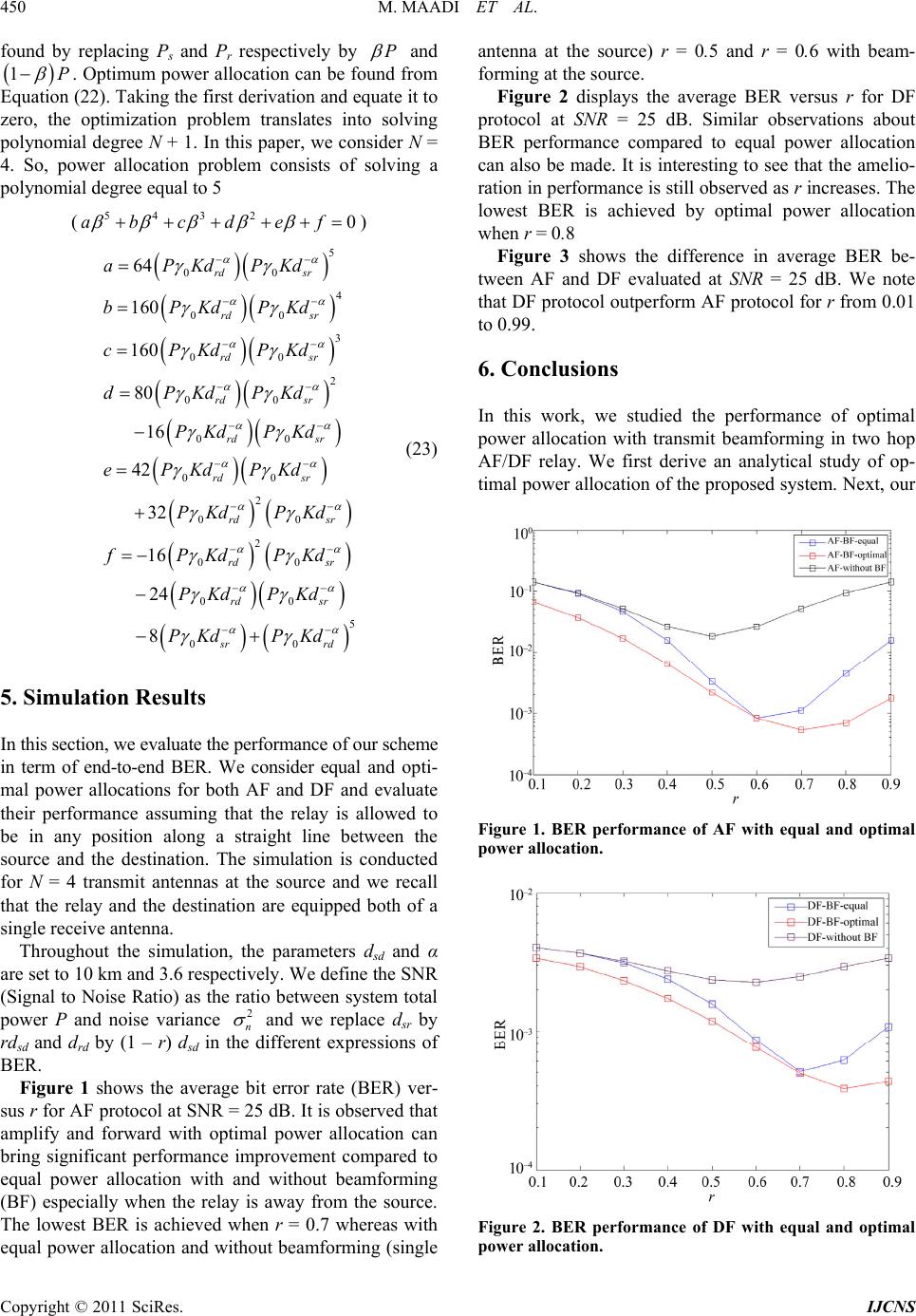 M. MAADI ET AL. Copyright © 2011 SciRes. IJCNS 450 found by replacing Ps and Pr respectively by P and 1P . Optimum power allocation can be found from Equation (22). Taking the first derivation and equate it to zero, the optimization problem translates into solving polynomial degree N + 1. In this paper, we consider N = 4. So, power allocation problem consists of solving a polynomial degree equal to 5 (543 20abcd ef ) 5 00 4 00 3 00 2 00 00 00 2 00 2 00 00 64 160 160 80 16 42 32 16 24 rd sr rd sr rd sr rd sr rd sr rd sr rd sr rd sr rd aPKdPKd bPKdPKd cPKdPKd dPKdPKd PKd PKd ePKdPKd PKdPKd fPKdPKd PKdPKd 5 00 8 sr sr rd PKd PKd (23) 5. Simulation Results In this section, we evaluate the performance of our scheme in term of end-to-end BER. We consider equal and opti- mal power allocations for both AF and DF and evaluate their performance assuming that the relay is allowed to be in any position along a straight line between the source and the destination. The simulation is conducted for N = 4 transmit antennas at the source and we recall that the relay and the destination are equipped both of a single receive antenna. Throughout the simulation, the parameters dsd and α are set to 10 km and 3.6 respectively. We define the SNR (Signal to Noise Ratio) as the ratio between system total power P and noise variance 2 n and we replace dsr by rdsd and drd by (1 – r) dsd in the different expressions of BER. Figure 1 shows the average bit error rate (BER) ver- sus r for AF protocol at SNR = 25 dB. It is observed that amplify and forward with optimal power allocation can bring significant performance improvement compared to equal power allocation with and without beamforming (BF) especially when the relay is away from the source. The lowest BER is achieved when r = 0.7 whereas with equal power allocation and without beamforming (single antenna at the source) r = 0.5 and r = 0.6 with beam- forming at the source. Figure 2 displays the average BER versus r for DF protocol at SNR = 25 dB. Similar observations about BER performance compared to equal power allocation can also be made. It is interesting to see that the amelio- ration in performance is still observed as r increases. The lowest BER is achieved by optimal power allocation when r = 0.8 Figure 3 shows the difference in average BER be- tween AF and DF evaluated at SNR = 25 dB. We note that DF protocol outperform AF protocol for r from 0.01 to 0.99. 6. Conclusions In this work, we studied the performance of optimal power allocation with transmit beamforming in two hop AF/DF relay. We first derive an analytical study of op- timal power allocation of the proposed system. Next, our Figure 1. BER performance of AF with equal and optimal power allocation. Figure 2. BER performance of DF with equal and optimal power allocation. 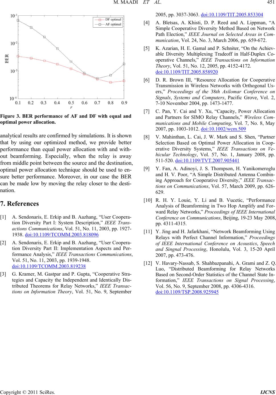 M. MAADI ET AL. Copyright © 2011 SciRes. IJCNS 451 Figure 3. BER performance of AF and DF with equal and optimal power allocation. analytical results are confirmed by simulations. It is shown that by using our optimized method, we provide better performance than equal power allocation with and with- out beamforming. Especially, when the relay is away from middle point between the source and the destination, optimal power allocation technique should be used to en- sure better performance. Moreover, in our case the BER can be made low by moving the relay closer to the desti- nation. 7. References [1] A. Sendonaris, E. Erkip and B. Aazhang, “User Coopera- tion Diversity Part I: System Description,” IEEE Trans- actions Communications, Vol. 51, No. 11, 2003, pp. 1927- 1938. doi:10.1109/TCOMM.2003.818096 [2] A. Sendonaris, E. Erkip and B. Aazhang, “User Coopera- tion Diversity Part II: Implementation Aspects and Per- formance Analysis,” IEEE Transactions Communications, Vol. 51, No. 11, 2003, pp. 1939-1948. doi:10.1109/TCOMM.2003.819238 [3] G. Kramer, M. Gastpar and P. Gupta, “Cooperative Stra- tegies and Capacity the Independent and Identically Dis- tributed Theorems for Relay Networks,” IEEE Transac- tions on Information Theory, Vol. 51, No. 9, September 2005, pp. 3037-3063. doi:10.1109/TIT.2005.853304 [4] A. Bletsas, A. Khisti, D. P. Reed and A. Lippman, “A Simple Cooperative Diversity Method Based on Network Path Election,” IEEE Journal on Selected Areas in Com- munication, Vol. 24, No. 3, March 2006, pp. 659-672. [5] K. Azarian, H. E. Gamal and P. Schniter, “On the Achiev- able Diversity Multiplexing Tradeoff in Half-Duplex Co- operative Channels,” IEEE Transactions on Information Theory, Vol. 51, No. 12, 2005, pp. 4152-4172. doi:10.1109/TIT.2005.858920 [6] D. R. Brown III, “Resource Allocation for Cooperative Transmission in Wireless Networks with Orthogonal Us- ers,” Proceedings of the 38th Asilomar Conference on Signals, Systems and Computers, Pacific Grove, Vol. 2, 7-10 November 2004, pp. 1473-1477. [7] C. Pan, Y. Cai and Y. Xu, “Capacity, Power Allocation and Partners for SIMO Relay Channels,” Wireless Com- munications and Mobile Computing, Vol. 7, No. 8, May 2007, pp. 1003-1012. doi:10.1002/wcm.509 [8] V. Mahinthan, L. Cai, J. W. Mark and S. Shen, “Partner Selection Based on Optimal Power Allocation in Coop- erative Diversity Systems,” IEEE Transactions on Ve- hicular Technology, Vol. 57, No. 1, January 2008, pp. 511-520. doi:10.1109/TVT.2007.905441 [9] Y. Fan, A. Adinoyi, J. S. Thompson, H. Yanikomeroglu and H. V. Poor, “A Simple Distributed Antenna Combin- ing Approach for Cooperative Diversity,” IEEE Transac- tions on Communications, Vol. 57, March 2009, pp. 626- 629. [10] R. H. Y. Louie, Y. Li and B. Vucetic, “Performance Analysis of Beamforming in Two Hop Amplify and For- ward Relay Networks,” Proceedings of IEEE International Conference on Communications, Beijing, 19-23 May 2008, pp. 4311-4315. [11] Y. Jing and H. Jafarkhani, “Network Beamforming Using Relays with Perfect Channel Information,” Proceedings of IEEE International Conference on Acoustics, Speech and Singnal Processing, Honolulu, Vol. 3, 15-20 April 2007, pp. 473-476. [12] V. Havary-Nassab, S. Shahbazpanahi, A. Grami and Z. Q. Luo, “Distributed Beamforming for Relay Networks Based on Second-Order Statistics of the Channel State In- formation,” IEEE Transactions on Signal Processing, Vol. 56, No. 9, September 2008, pp. 4306-4316. doi:10.1109/TSP.2008.925945 |