 Journal of Software Engineering and Applications, 2011, 4, 356-370 doi:10.4236/jsea.2011.46041 Published Online June 2011 (http://www.SciRP.org/journal/jsea) Copyright © 2011 SciRes. JSEA Building a Project Memory Using Semantic Design Rationale Process Sonia Gueraich, Zizette Boufaîda Department of Computer Science, LIRE Laboratory, University Mentouri of Constantine, Constantine, Algeria. Email: {sonia.gueraich, zboufaida}@gmail.com Received May 6th, 2011; revised May 30th, 2011; accepted June 17th, 2011. ABSTRACT In the proposal, a construction project memory process based on the semantic annotation is presented. A project Mem- ory concerns the representa tion and the identification of the exp erience acquired during projects realization. Th e main feature of this approach is tha t th e seman tic an nota tion is used to build a contin uous seman tic d esign rationa le process. We propose in this paper, a semantic traceability in four stages (identifying, structuring, annotating and integrating). The identificatio n and the structu ring phases use a model called Extended Margu erite model which fully considers the objectives of the project memory. The annotation phase exploits the results of precedent phase to prepare the final phase. Examples are presented from a case study in an Algerian firm called ENMTP. The architecture supporting the modelling engine is presented. Finally, an evaluation of the degree of the semantic annotation brought by proposed process is given. Keywords: Project Memory, Knowledge Capitalization, Ontology, Semantic Annotation, Design Rati on a l e 1. Introduction Knowledge in companies becomes an organisational asset for competitiveness and survival. One approach for managing knowledge in an organisation, is to set up an organisational memory management solution that ensures the persistent storage and/or indexing of the knowledge. An organisational memory relies on know- ledge resources i.e., documents, people, formalised knowledge and other artefacts in which knowledge has been embedded. Knowledge management is a process of clarification, modelling, share and appropriation of knowledge. It is in charge of capturing relevant pieces of knowledge and providing the concerned persons with them at the appropriate time, with the right level of details and in an adequate format [1]. The activity of knowledge management addresses problems of identification, ac- quisition, storage, access, diffusion, reuse and mainte- nance of both internal and external knowledge. The former represents the explicit knowledge formalized and transmitted using syntactic rules and semantic rep- resentations, whereas the latter references to tacit knowledge, fewtransferable and can not be considered outside th e activi ty that i mplemen ts it. The capitalization of know-how aims to develop the tacit knowledge owned and implemented by designers in order to reap the benefits. Grundstein [2] considers four stages, which are the identification, preservation, enhancement and updatingThe knowledge is then re- garded as objects, modelled by methods such as MKSM [3] and Common KADS [4]. This type of ap- proach has enabled the development of industrial tools that hadbrought significant gains in productivity. In Knowledge management vision, we are interested to a particular kind of process called Project Memory Management. It is acquired in the context of a project that must be saved with the knowledge to preserve its meaning [5]. It comprises the project definition, activi- ties, history and results [6].Numbers of knowledge management methods con- sider a project memory as a patrimony of knowledge of an organization. [7] Clas- sify these methods in two main categories: knowledge capitalization methods and direct extraction methods. The first category uses basis techniques of knowledge engineering. The second category, extracts knowledge directly from the com- pany activities. Several tech- niques are used basing on design rationale, statistical analysis, linguistic analysis, and communication trace- ability activities. In this paper, we propose to combine the use of the two categories through the semantic an-  Building a Project Memory Using Semantic Design Rationale Process357 notation techniques. The semantic annotation that we use is based on domain ontology [8]. The Semantic Web proposes an- notating document content using the semantic informa- tion from domain ontologies [9]. So, semantic annota- tion techniques can offer models to enrich these on- tologies and to work on them to perform tasks like the building of a company project memory. In this work, we are interested to the design of a project memory using a semantic annotation process. The latter, relies on the traceability of the design ra- tionale. One o f the principal p roblems in this tra ceabil- ity is the dynamic semantic annotation modelling. In other word, the problem is how to provide the project concerned persons with the relevant pieces of knowl- edge at the appropriate time, with the right level of details and the adequate format of presentation. The knowledge extracted in the initial project stages is not complete and not coherent as the knowledge ob- tained at the end of a project. So, we propose a seman- tic traceability process in four stages: identifying, structuring, annotating and integrating. In the structur- ing phase, we use a corporate memory model inspired from the Marguerite model [10] and we use the UML [11] diagrams to present stereotypes of annotated ac- tivities. In this paper, we propose an approach for building a project memory in the context of the design rationale and the semantic annotation. It is structured as follows. In Section 2, we introduce the concept of a project memory and our vision on it. Then, in Section 3, we present the elaborated Marguerite model. The ontol- ogies required by the annotation process are presented in Section 4. In Section 5, we propose the annotation process. Finally, we will compare our approach to re- lated work. 2. Project Memory as a Company Component Now days, there is an increasing economical interest in the capitalization of dispersed knowledge (both theoreti- cal knowledge and practical know-how) in a company. The coherent in tegration of this disp ersed knowledg e in a corporation is called Corporate Memory [12]. A Project Memory (PM) is a special type concerning a project and its realization. It includes lessons and experiences from given projects [5]. It also, contains project definition ac- tivities, history and results [6]. [13] Define a project memory as knowledge and information memory acquired and produced during the realization of projects. We focus in this paper on the project memory in the field of design. A project memory project must provide access to information describing both the characteristics of a project than those relating to the resolution of the problems encountered during the project [5]. We inte- grate the ontology component to provide primitives for the description of both users and company context pro- jects. So, we define, the PM as project knowledge resource including context, documents, ontology and annotations required for describing project definition activities, his- tory and results. For each component, we consider the memory project features (characteristics) and the project memory design rationale (problems). So, we obtain eight points of views. Figure 1 presents our structure for the PM. Memory Project features allows describing informa- tion and knowledge concerning project environment (or- ganization) and its results. In the context, we define the participants, tasks assigned, guidelines, design methods, requirement. Documents include technical resources (texts), models, hardware and software documentations. A memory project features point of view supports an organisational model which is an explicit representation of the structure, activities, processes, flows, resources, people, behaviour, goals, and constraints of an organisa- tion. The corresponding ontology captures the essential characteristics of the modelled entities and forms of rela- tions existing between them in an unambiguous consen- sual manner. The ontology provides the conceptual vo- cabulary to embed semantic annotations in the PM do- cuments. Annotations as a part of the PM can be in- serted anywhere in a web document related to an original document by using approporiate tags. Annotations are also, stocked in the appropriate annotations data base. In the project memory design rationale point of view, the knowledge is invested in making decision and in de- scribing the problems encountered and their resolutions. Table 1 summarizes the PM commonents according to the two points of view. We have classified the problems into fo ur classes. The first class concerns the project context problems (pro- Figure1. Project Memory structure. Copyright © 2011 SciRes. JSEA  Building a Project Memory Using Semantic Design Rationale Process Copyright © 2011 SciRes. JSEA 358 Table 1. PM components. features Problems resolutio Context organization participants projects products Positive Negative non reso Document hardware software Forms Contents + / – / 0 Ontology concepts relations Building Reuse + / – / 0 Annotation instanciation extraction Anomalies + / – / 0 the extraction parts. We consider like in [13] th at a prob- lem can be both an objective and a part of the resolution process. But, we differ in considering that the evaluation of solutions can include a third aspect which is the non resoluted case (with peer or good apreciations). In our work, before building a PM, we propose ten criterions for its definition. We have formulated them by considering the oncologic, semantic and design rationale aspects. [14] Have formulated seven requirements for semantic annotation systems (for the document centric model). So, we have adopted some of them to the PM definition and formulated them as criteria. Figure 2 pre- sents them in a Use Case UML diagram. We can resume them in the following points: posed design, requirements, project organization, par- ticipants, product problems). The second class describes documents problems (versions, authors, modifications). Criterion 1: Project Memory needs: The needs for building a PM may depend on the company size (wide, medium or small). We agree with [15] in the following enumeration of these needs. 1) to avoid the loss of know The third class permits to resence ontology problems related specially to its construction and reuse. The final class gives the problems encountered during the annota- tion process like instance ambiguities and anomalies in Figure 2. Criterion use case diagram.  Building a Project Memory Using Semantic Design Rationale Process359 how of a specialist after his mutation, death or retirement, 2) to exploit the experience acquired from past projects in order to avoid to reproduce some mistakes, 3) to ex- ploit the knowledge map of the company for the corpo- rate strategy, 4) to improve information circulation and communication, 5) to improve learning of employees, 6) to different know how. Criterion 2: Project Memory classifications: Co nsider s the project characteristics and the design rationale points of view. Criterion 3: Project Memory model: The core in building a PM is to be supported by a model. In our work, we have proposed the model of the Extended Marguerite presented in the section 3. Th is model covers the PM life cycle through its petals. Criterion 4: Support of heterogeneous documents: We consider the PM as a collection of documents and the work with multiple documents formats will become a necessary requirement. Criterion 5: Support of intelligent documents: [14] de- fine an intelligent document as a document which “knows about” its own content in order that automated processes can “know what to do” with it. So, we can consider an intelligent PM such a PM containing intelli- gent documents that can be formalized as web pages. Criterion 6: Support of documents evolution: We con- sider that the consisten cy and the flexibility of a PM fol- low the dynamic creation and evolution of both the documents and the related ontologies. So, we propose to deal with many document versions. Criterion 7: Ontology support: To manage a PM, we consider that the existence of one or more ontologies is useful for a semantic point of view. The semantic anno- tation is the bridge between the PM documents that are in general not structured or semi structured and their se- mantic ontological structured format. So, the changes resulting from the ontology population during company life cycle deal to resolve the possible inconsistency be- tween evolving ontologies and annotation tools. Criterion 8: User centred/collaborative design: The conception of a PM demands the collaboration between the different actors: experts, annotators, employers, etc. So, the annotation tools using standard formats give shared interfaces between enterprise actors. The sim- plicity and the flexibility of such interfaces help them performing the annotation task as a daily collaborative work. Criterion 9: Annotation storage: The design of a PM is a part of an organization Knowledge management Sys- tem (KM). So, we consider the exigencies of a KM en- vironment to the Semantic Web too ls. The Semantic Web model assumes that annotations will be stored separately from the original document. It decouples semantic and content. We assume that the PM documents are separated from their annotation storage, but with some restrictions for particular cases for reasons of controlling document versions. Criterion 10: Automation: We consider that the use of the manual annotation tools is not sufficient to follow the company evolution. So, the use of a combination of the automated and the manual tools seems a rational idea. So, we propose to use some natural language processing methods for the annotation of a PM. We motivate that in helping company actors to exploit it efficiently without prerequisite experiences. In the practice we have used for each project a criterion sheet. Then we have associated to it an EMK (Elements of Memory Knowledge) document. It is similar to the EC REX elements [16]. It contains a textual description of a project task and its eventual problems which, once restored, will be valued by users. The EMK elements are a part of the PM model presented in the following section. 3. Corporate Memory Model To describe the proposed model, we presented it in the Figure 3. The model called Extended Marguerite model (EM) [17] is inspired from the Marguerite model elabo- rated within the club of knowledge management [10]. The latter, was elaborated for the Knowledge Manage- ment Life Cycle. It is composed of four processes which correspond to the petals of the model: the process of the capitalization and the share of knowledge, the process of the interaction with the environment, the process of the learning and the creativity, the process of the selection and finally the heart which is composed by the process of the evaluation of the knowledge patrimony. So, we have modified this model for two reasons: the first is to adapt it to th e conception of a PM which will be annotated after. The second is to give a special descrip- tion to the PM Life Cycle. For annotating the PM and to remain in the Web Se- mantic context, we consider the final format of the documents as web pages. If they are not, we consider that the PM designer must transform them to web pages documents. We suppose also, that in this annotation phase, we begin to construct the ontology. This initiativ e may gain time and efforts and diminish costs. In the EM model, we have proposed three kinds of petals plus the heart composed from grains. The whole take the form of a flower called the “Marguerite”. The first category of petals is the Life cycle petals composed of Needs Identification, Building, Use and Maintenance petals. The second category is the Capitalization petals. The third category is the Interaction petals. We have summarized the essential of the model in Table 2. In the Copyright © 2011 SciRes. JSEA  Building a Project Memory Using Semantic Design Rationale Process 360 Figure 3. Extended Marguerite model. Table 2. EMM description petals. Life cycle petals: processes of constructing the original corporate memory Needs Identification petal Needed Tools Identify users, tasks, knowledge types they need to memorize and retrieve, ... EMK sheets + UML diagrams Building petal Tools Select the relevant documents + build Ontology document Management + ontology + Information Extraction tools (IE) + UML diagrams Use petal Needed Tools Exploit and broadcast PM Semantic Web tools + Intranet/Internet technologies Maintenance petal Needed tools Evaluate based on users’ satisfa c ti on . Gain measurement techniques Capitalization petals: ensure the recycling of the shared knowl edg e in the enterprise Needed tools: capitalization projec t methods Interaction petals: ensure the interaction with the en vironment Needed tools: Interaction methods Heart and grains: set of the knowledge manipulated in the enterpris e during its existence KM CW TE CM EI CK I PM components Knowledge Management Cooperative Work Technology Competence Management Economic Intelligence Crucial Knowledge Innovation Project Memory Components need identification petal, we use the EMK elements which are built primarily on the basis of interviews with project company experts, then on the documents analysis and the interrogation of existing databases. An EMK is typically composed of a header and a body (description). The header includes a title, an origin (the name of the project actors interviewed), the author, emission date emission, a description of the domain and the project context. The body contains opinions, comments and recommendations. Exploitation petal, concerns the use and the broadcast of the constructed PM. It is supposed to be manipulated by adequate members of the enterprise. An example of this use is the information retrieval which is generally applied in the info rmation search. This petal is adapted to the common users’ activities. The broadcasting of the PM is actually a necessary task. We have found that ac- tually a great number of companies use the Intranet/ Internet technologies. Capitalization petals include the process of the capi- talization and the share of the knowledge. So, they ensure the recycling of the shared knowledge in the enterprise. This petal is necessary to all petals of the first category. Interaction petals includ e the process o f the in teraction with the environment. So, the knowledge is updated by the information flows coming from the enterprise envi- ronment. This petal is in relation with the exploittation petal. Each petal has an internal link with the heart com- ponent and especially with the PM components. Each Copyright © 2011 SciRes. JSEA  Building a Project Memory Using Semantic Design Rationale Process361 heart grain petals, such Cooperative Work or Economic Intelligence reflects a part of the company orientation. The CK and PM components enumerate and catch traces of the different PM components. Especially they are the providers of the onlology concepts and relations elabo- rated in the following section. 4. PM Ontology In the Semantic Web, the ontologies required a good life cycle development: from the specification of needs to the implementation. [18] Consider that some companies build their own ontologies in order to construct a knowl- edge-base Corporate Memory relying on them. So, in this work we do not focus on the detailed presentation of the methodology adopted to construct our ontology, but we limit the purpose to some characteristics. The produced ontology is important in order to be used after by the semantic annotation. We are inspired from the many methods issues from the literature in the construction of the ontology. We have used the diagram of the Figure 4 to present construction steps and Table 3 to describe them. We use domain ontology; we motivate this choice, such in [18] by the reason to complete the definition of the enterprise model and to describe the concepts and their relations, related to the contents of the information sources. We have collected an essential part of the ontology components from the interviews carried out with the dif- ferent project actors and the company documents we have, also reused some ontologies such as O’Comma [19] ontology (which have reused many enterprise ontologies like: Enterprise, Tove , Pme). So, in the first step we have analyzed the informal version of the chosen onto- logies. In the second step, we have supervised the parts judged relevant for our context. We are also inspired from the sinificant parts of the “Information Manage- ment System Learner Information Package” [20]. It is structured into eleven categories, including: Identifica- tion, Goal (Goal), QCL (Qualifications, Certifications and Licenses), Competence, Access, Activity, Hobby (Interest), Affiliation, Security Key and Relationship. The PM ontology is a multicomponent domain onto- Figure 4. Ontology construction phases. Table 3. Construction steps. Construction steps Content Needs Analysis Techniques Based on the scenarios Semi-structured interviews, observation and document analysis Conceptualization Techniques Identification of concepts, relationships Diagrams and tables: - Building concepts axonomies and a binary relations diagram - Building a dictionary of concepts and a table of binary relations - Building a table of attributes and a logical axioms table - Building a table of instances and a table of instances relations Formalization Techniques Transformation in formal format (termi- nological level and assertional level) DL (Description logic) based on the syn- tax of SHIQ language Using Techniques Implementation (RDFS for the T-Box and the OWL for the A-box Evaluation and evolution Techniques Approbation of the ontology by the PM users Request tools logy composed of 5 ontologies, each concerned a precise domain. We present in Figure 5, the principal compo- nents of the ontology. The presentation is formalized as UML class diagram. These components are: Project Ontology: it is structured from the knowledge needed during a vehicle project that reflects the structure of a project. Technique Ontology: it is based on the official com- pany technical referential, corresponding to the vehi- cle components. Problem Ontology: it contains the problem types and it is eventually solutions made by the pro ject experts. Organizational Ontology: it corresponds to the com- pany organization (actors, ta sks, management ). Historical Ontology: it corresponds to the company archive. Each ontology is an n-leveled hierarchy of concepts linked vertically by “is-a” relations and horizontally lin ks by binary relations as “use” relations. 5. Semantic Design Rationale Process We propose four main steps (Figure 6) for the semantic design rationale process: identifying, structuring, anno- tating and integrating of the PM into company environ- ment. It is a continuous process (cycle). The principal objective of the iden tifying step is to de- fine the specifications of the PM system. We consider the latter as a part of the Knowledge Management system. This step is composed from three principal tasks: 1) Copyright © 2011 SciRes. JSEA  Building a Project Memory Using Semantic Design Rationale Process Copyright © 2011 SciRes. JSEA 362 Figure 5. Extract of elaborated ontology. Figure 6. Semantic design rationale process. clarification of the user’s needs to define necessary func- tionalities of the PM system, 2) definition of the re- quirements to be respected at the time of the systems design and finally, 3) evaluation of the requirements de- fined compared to the necessary functionalities. The definition of a PM model which respects the defi- nite requirements consist the input of the structuring steps. It lets the clarification of the specifications, and the definition of the PM components. The annotation step uses the semantic web and the automatic treatments of the natural language techniques. It produces a PM system. Finally, the integrating step elaborates architecture that can be compared to the given exigencies. Since we are interested to the design activity, we identify in each step three types of tasks. They are similar to those defined in the design task model sug- gested in Common KADS method. These tasks are the clarification of the needs, the design of a produ ct solution and the evaluation of the solution. The design actor is generally inspired from passed experiments to realize these tasks. He needs to consult information relating to problems in closed experiments, to know the solutions under some consideration, to obtain rejected options and to give their justifications and taken decisions. He needs to locate these problems in their context. To help him in performing the design activity, we propose to use the semantic annotation (manually and semi-automatic) as the core of the design rational process. The ontology provides the conceptual vocabulary to embed semantic annotations in the PM system. In the case study company intranets became the base of corporate memories. They are often based on web technologies and can therefore benefit from progresses made for the semantic web to improve the web exploitability through semantic annota- tions of its resources.  Building a Project Memory Using Semantic Design Rationale Process363 5.1. Semantic Annotation Step Since the PM is composed of heterogeneous changing documents, we structure them using semantic annotations expressed with primitiv es provided by a sh ared ontology. RDF and RDFS provide the framework to write the an- notations. RDF enables us to describe the content of PM documents through semantic an notations and use them to search for information. The idea is that 1) the company specifies concepts and their relationships in ontologies, 2) documents of the company are annotated using these ontologies and/ or extracting from documents themselves, 3) annotations are used to search the memory and navi- gate into it. Figure 7 illustrates the semantic annotating step. The semantic step can be performed in two ways. The first uses the ontology. In this case, the annotation is the instantiation of the document by ontology concepts. We can before instantiating the ontology use UML dia- grams elaborated from the EMK documents. We use EMK elements (textual descriptions) because they sum- marize the important pieces of knowledge and they are easy to perform UML diagrams from them. These dia- grams are used to enrich the existing ontology. The idea is that in some times enriching ontology and then anno- tating documents based on it can perform good annota- tions (well accepted by the user). The second way is to execute directly extraction techniques by referring to the ontology. The results are annotations presented in dif- ferent formats that can be supported by architecture and valuated by company actors. Based on this approach, we propose a methodology for generating semantic annota- tions in two parallel steps. In the following section, we present the annotation based on extraction. 5.2. Extraction Way Based on the literature in the field of the extraction [21,22], we propose the following phases: The first phase is to proceed by a series of linguistic analysis on the text in order to prepare it for the ex- traction phase; Figure 7. Semantic annotating step. The second is to locate instances of ontology relations and terms. Each relationship is characterized by a set of verbs and verb phrases, and the occurrence of any of these phrases in the text can be seen as an instan- tiation of that relationship. Each sentence containing a possible instance of terms is analyzed in order to ex- tract the instances of ontology con cepts linked by this relationship; The third phase is to generate a structured annotation based on ontology. For each document, a comprehen- sive annotation describing its content is generated as well. In the morpho-syntactic analysis, we retrieve all neces- sary knowledge characterizing the context. In our case, this analysis includes: Dividing the text into sentences by identifying the boundaries of each sentence for a possible specific treatment. Identification of basic linguistic entities (tokenization) composed from the words (tokens). It also includes the morphology of the entitie s (punctuation, nu mbers, etc.) and finds the root of each entity (stemming). Associating grammatical labelling to each token such noun, verb, adjective. In our architecture, we integrate two modules to per- form the first two stages which are the Sentence-Splitter and the Tokenizer and we use the grammatical Tree- Tagger for labelling. The orthomatcher and the gazetteers are also integrated. The modules are written on the base of the GATE [23] pl at form. In the detecting of semantic relations and terms, we identify the semantic relationships and the concepts al- ready modelled in the on tology. The identification of th e different forms of syntactic relations in the document forms the possible instances of relations formalized in the ontology. Semantic relationships are classified generally into two main categories: Syntagmatic relations, which are identifiable by a direct study of syntactic forms. Each relationship is characterized by one or more phrases (verbal, adjectival). These relationships are related to their arguments at the syntactic level. Paradigmatic rela- tions do not appear as direct syntactic relations, such as the synonymy and the heteronomy. The detection of such relationships usually requires human validation. In our work, we can use the two catego ries of relations. For the identificatio n of th e relation ships , we use a detec- tion grammar which is a grammar that covers the differ- ent syntactic forms of a relationship. Every relationship is associated with one or more grammars; the application of the grammar identifies a possible expression of this relationship. We used JAPE language (Java Annotation Patterns Engine) [23] to write our detection grammar of Copyright © 2011 SciRes. JSEA  Building a Project Memory Using Semantic Design Rationale Process Copyright © 2011 SciRes. JSEA 364 relationships. It can be applied on the GATE transducer. JAPE was proposed to write grammars which, when ap- plied, it adds information in the form of annotations. A Jape grammar has a set of phases; each phase is a set of rules as a pattern and action. In a rule if the pattern is satisfied, then an action may be triggered. The right side of a rule contains patterns that must be written in JAPE but the left side, which contains actions, they can be written in JAVA or JAPE. For the generation of semantic annotations, we gener- ate an overall semantic annotation for the whole docu- ment. We applied an annotation generation algorithm based on the [24] work. When an instance of a semantic relationship is detected, the following step is to identify- ing terms representing instances of ontology concepts that are in the same sentence. This identification is used to determine the terms of the ontology that can be linked by the detected relationship. In this phase, we have used Nomino [25] as a term extractor tool to provide the can- didate terms. Then we have written a wrapper that filter the list of candidate terms and kept only the instances of ontology concepts. 5.3. Instantiation Way In this step, we use manual annotations by exploiting existing tools such ontomat [26]. For enriching the on- tology by UML diagrams, we are inspired from the work of [27]. We have concretized the validity of the approach through an architecture (Figure 8) used in an Algerian industrial company. 5.4. Case Study The case study used is the project of prototyping cranes and loaders vehicle in ENMTP Company. The latter, is specialized in the development of all manufacture and distribution process related to public work s equipment of mechanical industry. We have observed many problems that increase the costs and times in design projects. For example last years, Figure 8. Approach architecture.  Building a Project Memory Using Semantic Design Rationale Process365 the company has known a set of voluntaries departures that have caused the loss of important mass of experience and knowledge. So, one solution can be the store and the management of the relevant prototyping knowledge. This makes the knowledge patrimony available for future projects. The vehicle product development cycle is made of re- petitive sub-cycles (design/development/validatio n/main- tenance). During a vehicle project design, the design de- partment checks that the parts satisfy the requirements of the product specifications. The project is starting from the most elementary functions until the final product de- sign. We have investigated through interviews with 35 pro- ject actors, the importance of the 10 criteria. We have summarized the results in Tab le 4 and presented them by Figure 9. For each criterion, we have numbered the in- terested actors, and then we have established the associ- ated percentages. We have observed that they are interested particularly by criterion 1, criterion 4, criterion 6, criterion 8 and cri- terion 10. So, the users are interested by knowing if there is a real need to implement a project memory, they are influenced by the evolution and the nature of the ma- nipulated documents. The users also, want to obtain adequate software and hardware that facilitate their d aily tasks. The remaining criteria, for the moment are not very attractive for them and for this reason; we have in- vestigated in the semantic web field by incorporating annotation and ontology tools. In this section we showcase the efficiency of the pro- posed approach, through using a scenario, as mentioned above. 5.4.1. Description of the Sce nar i o The scenario begins in the company with the choice of a project. In our case, we have chosen a project called “ex- tension of cranes and loaders”. It is a project initialled two years ago. In this project, the designers need to in- clude and understand how concerned materials problems can be resolved. They have observed that these problems can to be similar to those in other projects, having the same objective but in different contexts. The modelling of the PM documents begins by defin- ing the crucial documents containing explicit or implicit (case of experiences) knowledge. So, we propose a struc- Table 4. Criteria initially evaluated. criteria percents Criteria percents Criterion 1 25% Criterion 6 10% Criterion 2 5% Criterion 7 5% Criterion 3 5% Criterion 8 15% Criterion 4 15% Criterion 9 5% Criterion 5 5% Criterion 10 10% Figure 9. Criteria graphically presented. ture for each type of PM documents inspired from Rex elements, called EMKs. These structures were modelled by UML (Unified Modelling Language) class diagrams, and then they are coded in XML (eXtensible Markup Language) to be exploited as Semantic Web (SW) re- sources. We propose initially to generate empty XML docu- ments to fill by designers (manually annotation). Then, XSL sheets (extensible Stylesheet Language) were used. They control page setting of XML generated documents and let to visualize them by a web navigator. The docu- ments can thus be stored in XML data bases. In our case, we have generated 30 XML files (12 files for cranes and 18 for loaders). 5.4.2. Cons tru c ti on of the Ontology From a syntactic point of view, XML is considered as the standard layer that can benefit from all of the technolo- gies developed around the web [9]. From a semantic point of view, the goal of the semantic annotation pre- sented by XML is to enrich both the syntactic structures of documents and their semantic contents based on on- tologies. The implementation of ontology, built as part of this work is done in OWL (Ontology Web Language) in PROTEGE 3.1. OWL is the standard recommended by the W3C. Its advantage, in addition to its expressive power resides in the power of the inference services that are offered by RACER reasoner. Racer can interpret OWL documents and offers rea- soning services for both ontology levels: terminology (T_Box) and assertion (A_box) levels. At the termina- logy level, different types of queries can be used to: ver- ify the consistency of a concept, to check subsumption relations. At the assertion level, we can check th e consis- tency of the extracted instances of a particular class (concept), even according to various criteria, based on roles and attributes of the instances. We have used, the RQL (Racer Query Language) language, for querying ontology et the assertion level. Copyright © 2011 SciRes. JSEA  Building a Project Memory Using Semantic Design Rationale Process 366 The constructed ontology is composed from 219 con- cepts. These concepts are characterized by 20 attributes and 14 different relationships (7 inverse relationships included). To populate the ontology, we have given about 30 instances (on concepts and roles). Figure 10 presents the implemented ontology interface in PRO- TÉGÉ. 5.4.3. Sem ant ic Annotation Approach To illustrate our approach, we propose the following example: a designer after formulating an EMK document, he found the following sentence which described the problem of the not complete design in a crane engine. The EXTC1 problem concerns project s of crane pro- ducts The designer based on the ontology, navigates the im- plemented version and tries to check in the sentence the existence of ontology instances. We have proposed the use of the ontomat tool to help the designer in his search. The results of this task are seen as a semi-automatic an- notation. Then, the designer can summarize the result as presented in Figure 11. In the proposed approach, after, the morpho-syntactic analysis step, the sentence is divided in labelled words (EXTC1 is subject, concerns is verb). Then, after onto- logical step, we know that EXTC1 is an instance of the PROBLEM concept related to 2010 which is an instance of PROJECT concept. The generator module generates RDF documents and stores them in annotation databases. To evaluate the annotation in this step, we present some results of both quantitative and qualitative aspects for generating annotations. We believe that an ev aluation phase is necessary because the generation phase is costly and generally irreversible. The quality of a semantic an- notation (manually or generated semi-automatically), depends mainly on the quality of the method used for extracting information. In our work , evaluating quality of annotations consists to: Test the ability of detection grammars to detect all instances of possible semant i c relationships. Test the capacity of the terms extractor to identify all instances of concepts that can be linked by these rela- tions. Link good terms with the good relationship, while en- suring consistency with the domain model (i.e. on- tology). Figure 10. Ontology interface. Copyright © 2011 SciRes. JSEA 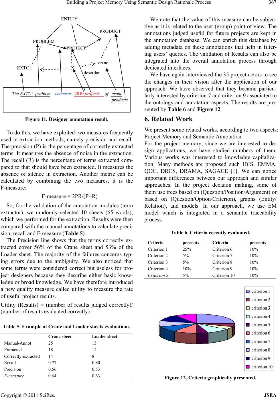 Building a Project Memory Using Semantic Design Rationale Process367 Figure 11. Designer annotation result. To do this, we have exploited two measures frequently used in extraction methods, namely precision and recall: The precision (P) is the percentage of correctly extracted terms. It measures the absence of noise in the extraction. The recall (R) is the percentage of terms extracted com- pared to that should have been extracted. It measures the absence of silence in extraction. Another metric can be calculated by combining the two measures, it is the F-measure: F-measure = 2PR/(P+R) So, for the validation of the annotation modules (term extractor), we randomly selected 10 sheets (65 words), which we performed for the ex traction. Results were th en compared with the manual annotations to calculate preci- sion, recall and F-measure (Table 5). The Precision line shows that the terms correctly ex- tracted cover 56% of the Crane sheet and 53% of the Loader sheet. The majority of the failures concerns typ- ing errors due to the ambiguity. We also noticed that some terms were considered correct but useless for pro- ject designers because they describe either basic know- ledge or broad knowledge. We have therefore introduced a new quality measure called utility to measure the rate of useful project results. Utility (Results) = (number of results judged correctly)/ (number of results evaluated correctly) Table 5. Example of Crane and Loader sheets evaluations. Crane sheet Loader sheet Manual-Annot 25 15 Extracted 18 14 Correctly-extracted 14 8 Recall 0.77 0.80 Precision 0.56 0.53 F-measure 0.64 0.63 We note that the value of this measure can be subjec- tive as it is related to the u ser (group) point of view. The annotations judged useful for future projects are kept in the annotation database. We can enrich this database by adding metadata on these annotations that help in filter- ing users’ queries. The validation of Results can also be integrated into the overall annotation process through dedicated interfaces. We have again interviewed the 35 project actors to see the changes in their vision after the application of our approach. We have observed that they became particu- larly interested by criterion 7 and criterion 9 associated to the ontology and annotation aspects. The results are pre- sented by Table 6 and Figure 12. 6. Related Work We present some related works, according to two aspects: Project Memory and Semantic Annotation. For the project memory, since we are interested to de- sign applications, we have studied numbers of them. Various works was interested to knowledge capitaliza- tion. Many methods are proposed such IBIS, EMMA, QOC, DRCS, DRAMA, SAGACE [1]. We can notice important differences between our approach and similar approaches. In the project decision making, some of them use trees based on (Question/Position/Argument) or based on (Question/Option/Criterion), graphs (Entity/ Relation), and models. In our approach, we use EM model which is integrated in a semantic traceability process. Table 6. Criteria recently evaluated. Criteria percents Criteria percents Criterion 1 25% Criterion 6 10% Criterion 2 5% Criterion 7 10% Criterion 3 5% Criterion 8 10% Criterion 4 10% Criterion 9 10% Criterion 5 5% Criterion 10 10% Figure 12. Criteria graphically presented. Copyright © 2011 SciRes. JSEA  Building a Project Memory Using Semantic Design Rationale Process 368 Other, works are interested to the integration of the Product/Process/Resource as three fundamental concepts in the description of an enterprise system. Examples of models were presented such as: FBS model (Function, Behaviour and Structure) [28] and FBS-PPRE (Function , Behaviour, Structure, Process, Product, Resource, Exter- nal) [29]. In our case, we have integrated the different pieces of the knowledge in ontology model. In his work, Smain Bekhti [30] relied on the work of [31]. He pro- poses a memory model using the formalism of semantics networks. His project memory is divided into a rational design memory (includes problem-solving and decision making components) and into a context memory repre- senting characteristics of the project. The context mem- ory is the set of elements that characterize the conduct and the organization of a project design. Smain Bekhti models do not take the advantage of more recent devel- opments object-oriented modelling including the gener- alization/specialization aspects In our work, we share the idea that a rationale design memory is invested in defin- ing objectives, solving problems and making decisions during a project. Also, we need to use a process of capi- talization, because it allows obtaining the different traces of the project memory. In our process we take into ac- count the aspects of development, documentation, or- ganization and justification. [31] Define a memory using Entity/Association formalism. It includes a product model to describe the various facets of product design and a process design model. The latter, describes the product design at different levels of detail showing why, how, who or what is on each stage of design. The force of this model resides in its strong integration between sub-models. However, it does not take into account the documentation, the justification and the argument of choices-making aspects and do not include object-ori- ented techniques. In [32] work, the main objective was the specification of a knowledge management tool for the design projects. The proposed model used domain archi- tecture which, through instantiation and fitness (for a particular context) can realize a project memory. He used UML graphs. We agree, with him for this choice, be- cause UML diagrams are well suited for inexperienced users, they offer relative clarity and more ability to rep- resent fairly and accurately the real world elements. Adding, to that, it is possible to move efficient models to computer implementation. For semantic annotation, KIM [33] identifies the Key Phrases and Named Entities (NE) and perfo rms semantic annotation automatically in respect to their ontology. They use GATE platform. Samovar [34] is a system de- veloped to capitalize knowledge in the automotive field (Renault). Samovar’s approach is based on the use of multiple ontologies (Problem, Component, Service and Project) built from databases and textual data extracted automatically from the databases. Ontologies are repre- sented in RDFS and used to create annotations on RDF. CA Manager [35] is a generic framework supporting semantic annotation based on any information extraction tool, and also any domain ontology. The force of this work is in preserving independences between the content augmentation tool and the semantic repositories. We have considered this point in our annotation process. Our approach is more flexible in the sense that we do not re- strict, the semantic annotation to only on the ontology, we can consider the tex tual elements. 7. Conclusions We presented semantic design rationale process. It elaborates the EM model which serves to the design of a Project Memory dedicated to an industrial company. This process is applied especially for the product design ap- plications. The model relies on the more general knowl- edge management phases. It uses UML diagrams to pre- sent the context, the documents, the ontology and the semantic annotation. The latter, is based on domain on- tology. The semantic annotation process is controlled by allowing human annotators to be involved. The main contribution of the ME model in comparison to other similar models is that it allows easy plug-in of know- ledge management approach (that focuses on a project memory), semantic design rationale process and onto- logies. We have created ontology for the ENMTP Company. We have also, used a semi-semantic annotation process on a project memory corpus by using instantiation way. The annotations based on extraction reach the level of human annotators. So, we could calculate precision and recall values. The objective is to evaluate the flexibility and the scalability of the approach and therefore realize the suitability for practical applications. REFERENCES [1] R. Dieng, O. Corby, F. Gandon, N. Matta and M. Ribière, “Kowledge Management: Méthodes et Outils pour la Gestion des Connaissances,” 3th Edition, Dunod, 2006. [2] M. Grunstein and J.-P. Barthès, “An Industrial View of the Process of Capitalizing Knowledge,” Proceedings of ISMICK’96, Rotterdam, Vol. 1, October 2006, pp. 258- 264. [3] J. L. Ermine, M. Chaillot, P. Bigeon, B. Charreton and D. Malavielle, “MKSM: Méthode Pour la Gestion des Connaissances,” Ingénierie des systèmes d’Information, AFCET-Hermès, Vol. 4, No. 4, 1996, pp. 540-575. [4] G. Schreiber, H. Akkermans, A. Anjewierden, R. Dehoog, N. Shadbolt, W. Vandervelde and B. Wielinga “Know- ledge Engineering and Management: The CommonKads Copyright © 2011 SciRes. JSEA 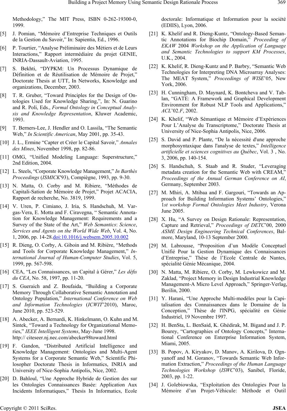 Building a Project Memory Using Semantic Design Rationale Process369 Methodology,” The MIT Press, ISBN 0-262-19300-0, 1999. [5] J. Pomian, “Mémoire d’Entreprise Techniques et Outils de la Gestion du Savoir,” In: Sapientia, Ed., 1996. [6] P. Tourtier, “Analyse Préliminaire des Métiers et de Leurs Interactions,” Rapport intermédiaire du projet GENIE, INRIA-Dassault-Aviation, 1995. [7] S. Bekhti, “DYPKM: Un Processus Dynamique de Définition et de Réutilisation de Mémoire de Projet,” Doctorate Thesis at UTT, In Networks, Knowledge and organizations, December, 2003. [8] T. R. Gruber, “Toward Principles for the Design of On- tologies Used for Knowledge Sharing,”, In: N. Guarino and R. Poli, Eds., Formal Ontology in Conceptual Analy- sis and Knowledge Representation, Kluwer Academic, 1993. [9] T. Berners-Lee, J. Hendler and O. Lassila, “The Semantic Web,” In Scientific American, May 2001, pp. 35-43. [10] J. L., Ermine “Capter et Créer le Capital Savoir,” Annales des Mines, November 1998, pp. 82-86. [11] OMG, “Unified Modeling Language: Superstructure,” 2nd Edition, 2004. [12] L. Steels, “Corporate Knowledge Management,” In Barthès Proceedings (ISMICK'93), Compiègne, 1993, pp. 9-30. [13] N. Matta, O. Corby and M. Ribiere, “Méthodes de Capitali-Sation de Mémoire de Projet,” Projet ACACIA, Rapport de recherche, No. 3819, 1999. [14] V. Uren, P. Cimiano, J. Iria, S. Handschuh, M. Var- gas-Vera, E. Motta and F. Ciravegna, “ Semantic Annota- tion for Knowledge Management: Requirements and a Survey of the State of the Art,” Web Semantics: Science, Services and Agents on the World Wide Web, Vol. 4, No. 1, 2006, pp. 14-28.doi:10.1016/j.websem.2005.10.002 [15] R. Dieng, O. Corby, A. Giboin and M. Ribière, “Methods and Tools for Corporate Knowledge Management,” In- ternational Journal of Human-Computer Studies, Vol. 5, 1999, pp. 567-598. [16] CEA, “Les Connaissances, un Capital à Gérer,” Les défis du CEA, No. 58, 1997, pp. 11-20. [17] S. Gueraich and Z. Boufaida, “Building a Corporate Memory Through Collaborative Semantic Annotation and Ontology Population,” International Conference on Web and Information Technologies (ICWIT’2010), Maroc, June 2010, pp. 523-529. [18] A. Abecker, A. Bernardi, K. Hinkelmann, O. Kuhn and M. Sintek, “Toward a Technology for Organizational Memo- ries,” IEEE Intelligent Systems, May-June 1998. http:// citeseer .nj.nec.com/abecker98toward.html [19] F. Gandon, “Distributed Artificial Intelligence and Knowledge Management: Ontologies and Multi-Agent Systems for a Corporate Semantic Web,” Scientific Phi- losopher Doctorate Thesis in Informatics, INRIA and University of Nice-Sophia Antipolis, Nice, 2002. [20] D. Bahloul, “Une Approche Hybride de Gestion des sur les Ontologies Connaissances Basée: Application Aux Incidents Informatiques,” Thesis In Informatics, Ecole doctorale: Informatique et Information pour la société (EDIIS), Lyon, 2006. [21] K. Khelif and R. Dieng-Kuntz, “Ontology-Based Seman- tic Annotations for Biochip Domain,” Proceeding of EKAW 2004 Workshop on the Application of Language and Semantic Technologies to support KM Processes, U.K., 2004. [22] K. Khelif, R. Dieng-Kunt z and P. Barbry , “Semant ic Web Technologies for Interpreting DNA Microarray Analyses: The MEAT System,” Proceedings of WISE’05, New York, 2006. [23] H. Cunningham, D. Maynard, K. Bontcheva and V. Tab- lan, “GATE: A Framework and Graphical Development Environment for Robust NLP Tools and Applications,” ACL’02.F, 2002. [24] K. Khelif, “Web Sémantique et Mémoire d’Expériences Pour L’Analyse du Transcriptome,” Doctorate Thesis at University of Nice-Sophia Antipolis, Nice, 2006. [25] S. David and P. Plante, “De la nécessité d'une approche morphosyntaxique dans l'analyse de textes,” Intelligence artificielle et sciences cognitives au Québec, Vol. 3 , No. 3, 2006, pp. 140-154. [26] S. Handschuh, S. Staab and R. Studer, “Leveraging metadata creation for the Semantic Web with CREAM,” Proceedings of the Annual German Conference on AI, Germany, September 2003. [27] M. Mhiri, A. Mtibaa and F. Gargouri, “Towards an Ap- proach for Building Information Systems’ Ontologies,” 1st workshop Formal Ontologies Meet Industry, Verona June 2005. [28] X. Hu, “A Survey on Design Rationale: Representation, Capture and Retrieval,” Proceedings of DETC’00, 2000 ASME Design Engineering Technical Conferences, Bal- more, Maryland, 10-13 September 2000. [29] M. Labrousse, “Proposition d’un Modèle Conceptuel Unifié Pour la Gestion Dynamique des Connaissances d’Entreprise,” Thèse de l’Ecole Centrale de Nantes, spécialité Génie Mécanique, 2004. [30] N. Matta, M. Ribiere, O. Corby, M. Lewkowicz and M. Zaklad, “Project Memory in Design Industrial Knowledge Management-A Micro Level Approach,” Springer-Verlag, Berilin, 2000. [31] Y. Harani, “Une Approche Multi-modèles pour la Capi- talisation des Connaissances dans le Domaine de la Conception,” Thèse de l'INPG, spécialité en Génie Industriel, 19 Novembre 1997. [32] H. BenSta, L. BenSaid, K. Ghédirak, M. Bigand and J. P. Bourey, “Cartographies of Ontology Concepts,” Interna- tional Conference on Enterprise Information System, Miami, 2005. [33] B. Popov, A. Kiryakov, D. Manov, A. Kirilova, D. Ogn- yanoff and M. Goranov, “Towards Semantic Web Infor- mation Extraction,” Proceedings of the Human Language Technologies Workshop (ISWC’03), Sanibel, Floride, 2003, pp. 1-22. [34] J. Golebiowska, “Exploitation des Ontologies Pour la Mémoire d’un Projet-Véhicule: Méthode et Outil Copyright © 2011 SciRes. JSEA  Building a Project Memory Using Semantic Design Rationale Process Copyright © 2011 SciRes. JSEA 370 SAMOVAR,” Ph.D. Computer Science Thesis, Univer- sity of Nice Sophia Antipolis, 4 February 2002. [35] F. Amardeilh, D. Damljanovic and K. Bontcheva, “CA Manager: A Framework for Creating Customised Work- flows for Ontology Population and Semantic Annotation,” Semantic Authoring, Annotation and Knowledge Markup Workshop, Los Angeles, 2009.
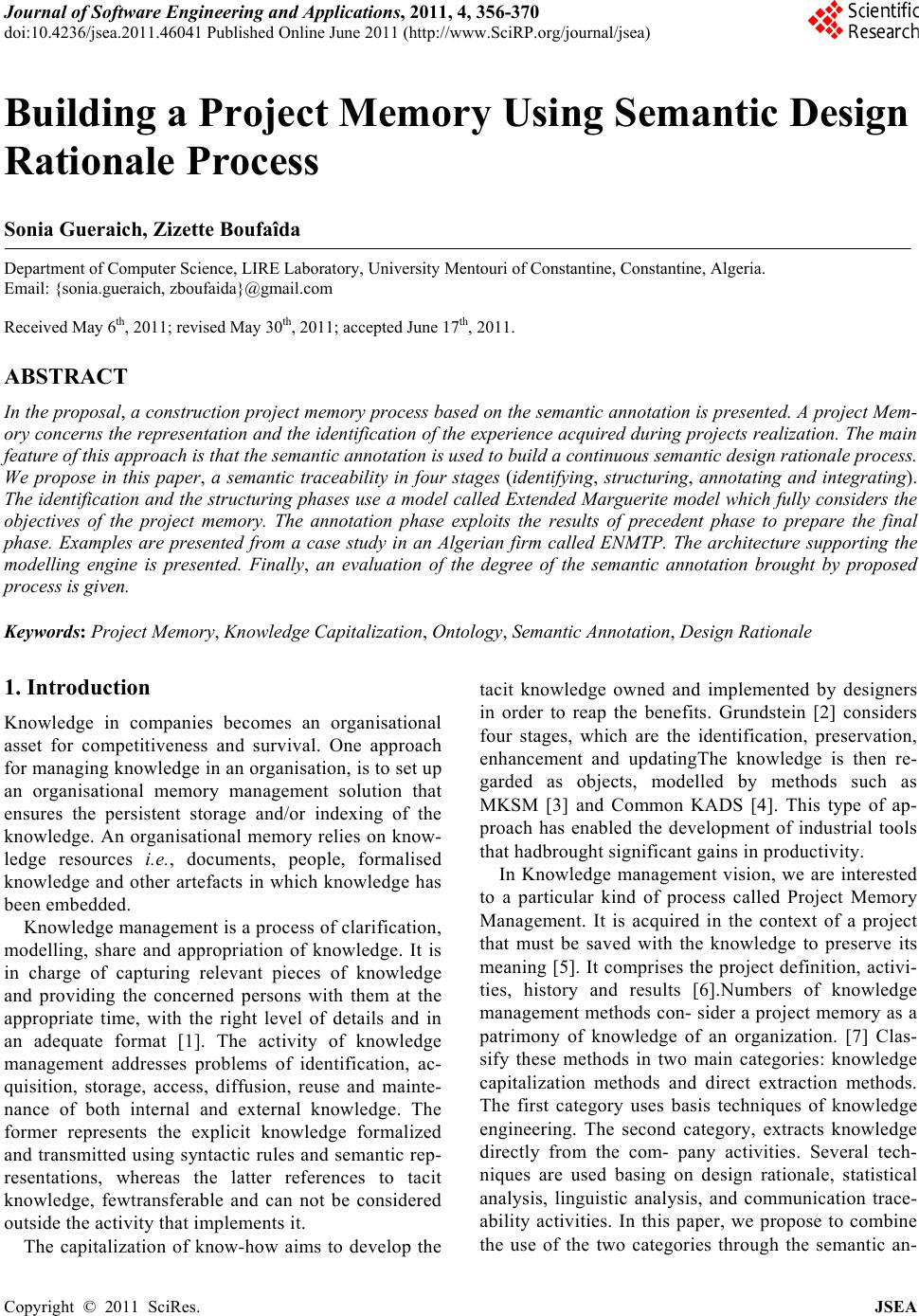
|