Paper Menu >>
Journal Menu >>
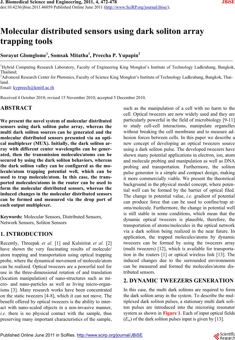 J. Biomedical Science and Engineering, 2011, 4, 472-478 JBiSE doi:10.4236/jbise.2011.46059 Published Online June 2011 (http://www.SciRP.org/journal/jbise/). Published Online June 2011 in SciRes. http://www.scirp.org/journal/JBiSE Molecular distributed sensors using dark soliton array trapping tools Sorayut Glomglome1, Somsak Mitatha1, Preecha P. Yupapin2 1Hybrid Computing Research Laboratory, Faculty of Engineering King Mongkut’s Institute of Technology Ladkrabang, Bangkok, Thailand; 2Advanced Research Center for Photonics, Faculty of Science King Mongkut’s Institute of Technology Ladkrabang, Bangkok, Thai- land. Email: kypreech@kmitl.ac.th Received 4 October 2010; revised 15 November 2010; accepted 5 December 2010. ABSTRACT We present the novel system of molecular distributed sensors using dark soliton pulse array, whereas the multi dark soliton sources can be generated and the molecular distributed sensors presented via an opti- cal multiplexer (MUX). Initially, the dark soliton ar- ray with different center wavelengths can be gener- ated, then the transmission molecules/atoms can be secured by using the dark soliton behaviors, whereas the dark soliton valley can be configured as the mo- lecule/atom trapping potential well, which can be used to trap molecule/atom. In this case, the trans- ported molecules/atoms in the router can be used to form the molecular distributed sensors, whereas the induced changes in the molecular distributed sensors can be formed and measured via the drop port of each output multiplexer. Keywords: Molecular Sensors, Distributed Sensors, Network Sensors, Soliton Sensors 1. INTRODUCTION Recently, Threepak et al. [1] and Kulsirirat et al. [2] have shown the very fascinating results of molecule/ atom trapping and transportation using optical trapping probe, where the dynamical movement of molecule/atom can be realized. Optical tweezers are a powerful tool for use in the three-dimensional rotation of and translation (location manipulation) of nano-structures such as mi- cro- and nano-particles as well as living micro-organ- isms [3]. Many research works have been concentrated on the static tweezers [4-8], which it can not move. The benefit offered by optical tweezers is the ability to inter- act with nano-scaled objects in a non-invasive manner, i.e. there is no physical contact with the sample, thus preserving many important characteristics of the sample, such as the manipulation of a cell with no harm to the cell. Optical tweezers are now widely used and they are particularly powerful in the field of microbiology [9-11] to study cell-cell interactions, manipulate organelles without breaking the cell membrane and to measure ad- hesion forces between cells. In this paper we describe a new concept of developing an optical tweezers source using a dark soliton pulse. The developed tweezers have shown many potential applications in electron, ion, atom and molecule probing and manipulation as well as DNA probing and transportation. Furthermore, the soliton pulse generator is a simple and compact design, making it more commercially viable. We present the theoretical background in the physical model concept, where poten- tial well can be formed by the barrier of optical filed. The change in potential value, i.e. gradient of potential can produce force that can be used to confine/trap at- oms/molecule. Furthermore, the change in potential well is still stable in some conditions, which mean that the dynamic optical tweezers is plausible, therefore, the transportation of atoms/molecules in the optical network via a dark soliton being realized in the near future. In application, the trapped molecules/atoms by dynamic tweezers can be formed by using the tweezers array (multi tweezers) [12], which is available for transporta- tion in the routers [1] or optical wireless link [13]. The induced changes due to the surrounded environments can be measured and formed the molecules/atoms dis- tributed sensors. 2. DYNAMIC TWEEZERS GENERATION In this case, the multi dark solitons are required to form the dark soliton array in the system. To describe the mul- tiplexed dark soliton pulses, a stationary multi dark soli- ton pulses are introduced into the microring resonator system as shown in Figure 1. Each of input optical fields (Ein) of the dark soliton pulses input is given by [13].  S. Glomglome et al. / J. Biomedical Science and Engineering 4 (2011) 472-478 Copyright © 2011 SciRes. JBiSE 473 0 0 tanhexp 2 in D Tz Et Ait TL (1) Where A and z are the optical field amplitude and prop- agation distance, respectively. T is a soliton pulse prop- agation time in a frame moving at the group velocity, T = t – β1 * z, where β1 and β2 are the coefficients of the linear and second-order terms of Taylor expansion of the propagation constant. LD = 2 0 T/|β2| is the dispersion length of the soliton pulse. T0 in equation is a soliton pulse propagation time at initial input (or soliton pulse width), where t is the soliton phase shift time, and the frequency shift of the soliton is ω0. This solution describes a pulse that keeps its temporal width invariance as it propagates, and thus is called a temporal soliton. When a soliton peak intensity (|β2/Г × 2 0 T|) is given, then T0 is known. For the soliton pulse in the microring device, a balance should be achieved between the dispersion length (LD) and the nonlinear length (LNL = 1/Г φ NL), where Г = n2 * k0, is the length scale over which dispersive or nonli- near effects makes the beam become wider or narrower. For a soliton pulse, there is a balance between dispersion and nonlinear lengths, hence LD = LNL. When light propagates within the nonlinear material (medium), the refractive index (n) of light within the medium is given by 2 02 0 eff n nn nInp A (2) where n0 and n2 are the linear and nonlinear refractive indexes, respectively. I and P are the optical intensity and optical power, respectively. The effective mode core area of the device is given by Aeff. For the series micror- ing resonator (MRRs), the effective mode core areas range from 0.50 to 0.10 μm2 [14]. When a soliton pulse is input and propagated within a MRR, as shown in Figure 1, which consists of a series MRRs. The resonant output is formed, thus, the normalized output of the light field is the ratio between the output and input fields [Eout(t) and Ein(t)] in each roundtrip, which is given by [15]. 2 2 22 11 11 111 411sin 2 out in Et Et x xx (3) The close form of Equation (3) indicates that a ring reso- nator in this particular case is very similar to a Fabry- Perot cavity, which has an input and output mirror with a field reflectivity, (1 ), and a fully reflecting mirror. is the coupling coefficient, and x = exp (−αL/2) represents a roundtrip loss coefficient, 0 = kLn0 and φ NL= kLn2|Ein|2 are the linear and nonlinear phase shifts, k = 2π/λ is the wave propagation number in a vacuum, where L and α are waveguide length and linear absorption coef- ficient, respectively. In this work, the iterative method is introduced to obtain the results as shown in Equation (3), and similarly, when the output field is connected and in- put into the other ring resonators. The input optical field as shown in Equation (1), i.e. a dark soliton pulse, is input into a nonlinear series mi- Figure 1. Schematic of dark soliton array generation, where Eins: soliton inputs, Rs: ring radii, κs: coupling coefficients, MUX: optical multiplexer, Rd: Add/drop radius, MRR: microring resonator.  S. Glomglome et al. / J. Biomedical Science and Engineering 4 (2011) 472-478 Copyright © 2011 SciRes. JBiSE 474 croring resonator. By using the appropriate parameters, we propose to use the add/drop device with the appro- priate parameters. This is given in details as followings. The optical outputs of a ring resonator add/drop filter can be given by the Equations (4) and (5), respectively [16]. 2 2 112 2 2 121 2 1211cos 1 11 1211cos t in L L n L L n E E ekLe eekL (4) And 2 2 12 2 121 2 11 1211cos d in L L L n E E e eekL (5) where Et and Ed represent the optical fields of the throughput and drop ports, respectively β = kneff is the propagation constant, neff is the effective refractive index of the waveguide, and the circumference of the ring is L=2πR, with R as the radius of the ring. In the following, new parameters is used for simplification with = βL as the phase constant. The chaotic noise cancel- lation can be managed by using the specific parameters of the add/drop device, and the required signals can be retrieved by the specific users. 1 and 2 are the coupling coefficient of the add/drop filters, kn = 2πR is the wave propagation number for in a vacuum, and where the waveguide (ring resonator) loss is = 0.5 dBmm−1. The fractional coupler intensity loss is = 0.1. In the case of the add/drop device, the nonlinear refractive index is neglected. 3. MOLECULAR DISTRIBUTED SENS- ING MECHANISM In simulation, the generated dark soliton pulse, for in- stance, with 50-ns pulse width, and a maximum power of 0.65 W is input into each of ring resonator systems with different center wavelengths, as shown in Figure 1. The suitable ring parameters are used, such as ring radii and ring coupling coefficients, where R1 = 15.0 μm and R2 = 10.0 μm. In order to make the system associate with the practical device [14], n0 = 3.34 (InGaAsP/InP). The effective core areas are Aeff = 0.50 and 0.25 μm2 for MRRs. The waveguide and coupling loses are = 0.5 dBmm−1 and =0.1, respectively, and the coupling coefficients s of the MRRs are ranged from 0.03 to 0.1. The nonlinear refractive index is n2 = 2.2×10⁻¹³ m2/W. In this case, the waveguide loss used is 0.5 dBmm−1. However, more parameters are used as shown in Figure 1. The input dark soliton pulse is chopped (sliced) into the smaller signals R1, R2, and the filtering signals within add/drop ring Rd are seen. We find that Figure 2. Simulation result of the dark solitons within the series microring resonators when the dark soliton input wave- length is 1501 nm, where (a) dark soliton input, (b) and (c) dark solitons in rings R1 and R2, (d) is the drop port signals.  S. Glomglome et al. / J. Biomedical Science and Engineering 4 (2011) 472-478 Copyright © 2011 SciRes. JBiSE 475 the output signals from R2 is larger than from R1 due to the different core effective areas of the rings in the sys- tem, however, the effective areas can be transferred from 0.50 and 0.25 μm2 with some losses. The soliton signals in Rd is entered in the add/drop filter, where the dark soliton conversion can be performed by using Eqs.4 and 5. In application, the different dark soliton wavelength is input into the series microring resonators system, wheres the parameters of system are set the same. For instance, the dark solitons are input into the system at the center wavelengths λ1 =1501, λ2 = 1503 and λ3 = 1505 nm, re- spectively. When a dark soliton propagates into the MRRs system, the occurrence of dark soliton collision (modulation) in multiplexer system and the filtering sig- nals within add/drop ring (Rd) is as shown in Figure 1. The dark soliton generated by multi-light sources at the center wavelength λ1 = 1501 nm, the filtering signals are as shown in Figure 2. Simulation results obtained have shown that the band of bright solitons is seen, whereas there is no signal at λ1 = 1501 nm. The free spectrum range (FSR) and theamplified power of 2.15 nm and 80 W of the dark soliton are obtained, where in this case, the spectral width(Full width at half maximum, FWHM) of 0.073 nm is achieved. In Figure 3, the dark soliton Figure 3. Simulation result of the dark soliton array when the dark soliton input wavelengths are 1501, 1503 and 1505 nm, where (a) dark soliton array, (b), (d) and (f) are the output signals R2, (c),(e) and (g) are the drop port signals, respectively. 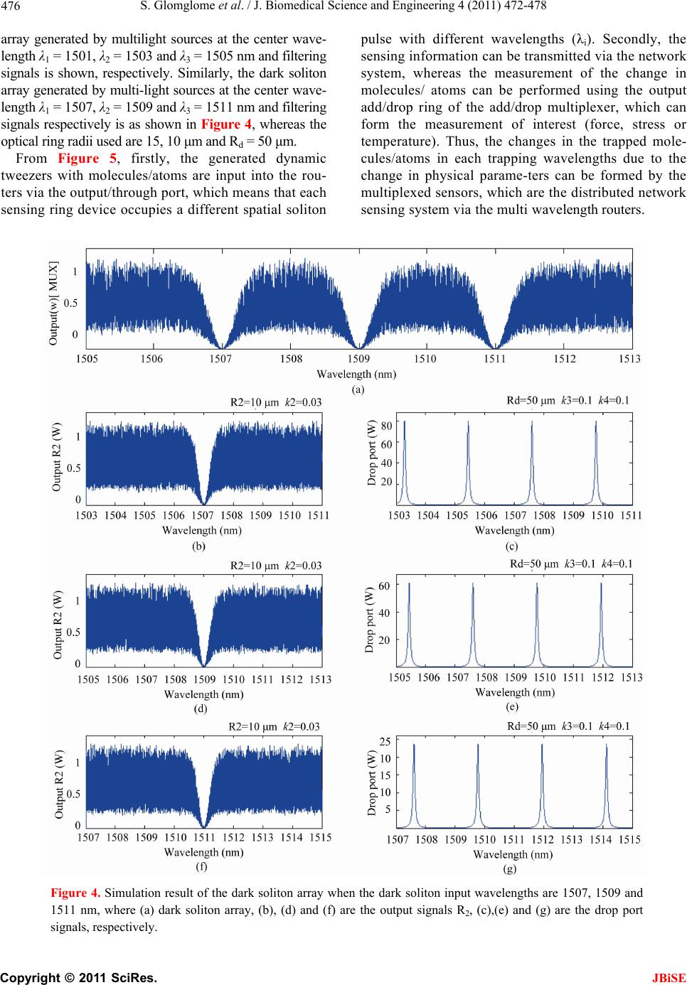 S. Glomglome et al. / J. Biomedical Science and Engineering 4 (2011) 472-478 Copyright © 2011 SciRes. JBiSE 476 array generated by multilight sources at the center wave- length λ1 = 1501, λ2 = 1503 and λ3 = 1505 nm and filtering signals is shown, respectively. Similarly, the dark soliton array generated by multi-light sources at the center wave- length λ1 = 1507, λ2 = 1509 and λ3 = 1511 nm and filtering signals respectively is as shown in Figure 4, whereas the optical ring radii used are 15, 10 μm and Rd = 50 μm. From Figure 5, firstly, the generated dynamic tweezers with molecules/atoms are input into the rou- ters via the output/through port, which means that each sensing ring device occupies a different spatial soliton pulse with different wavelengths (λi). Secondly, the sensing information can be transmitted via the network system, whereas the measurement of the change in molecules/ atoms can be performed using the output add/drop ring of the add/drop multiplexer, which can form the measurement of interest (force, stress or temperature). Thus, the changes in the trapped mole- cules/atoms in each trapping wavelengths due to the change in physical parame-ters can be formed by the multiplexed sensors, which are the distributed network sensing system via the multi wavelength routers. Figure 4. Simulation result of the dark soliton array when the dark soliton input wavelengths are 1507, 1509 and 1511 nm, where (a) dark soliton array, (b), (d) and (f) are the output signals R2, (c),(e) and (g) are the drop port signals, respectively.  S. Glomglome et al. / J. Biomedical Science and Engineering 4 (2011) 472-478 Copyright © 2011 SciRes. JBiSE 477 Figure 5. A system of distributed sensor via a multi wavelength routers, where Rd: ring radii, λi, λi: output wavelength, κi, κi1, κi2, κj, κj1, κj2: coupling constants. 4. CONCLUSION We present the technique of molecular distributed sen- sors using dark soliton array, whereas the multi dark solitons are input into the series microring resonators, which can be used to perform the large molecule/atom trapping capacity in the distributed networks. The multi- plexed and the filtering signals within add/drop filter can be generated and obtained. The use of dark soliton array to form the large number of molecule/atom trapping within the distributed sensing system is analyzed and discussed. REFERENCES [1] Threepak, T., Luangvilay, X., Mitatha, S. and Yupapin, P.P. (2010) Novel quantum-molecular transporter and networking via a wavelength router. Microwave and Op- tical Technology Letters, 52, 2104-2107. doi:10.1002/mop.25204 [2] Kulsirirat, K., Techithdeera, W. and Yupapin, P.P. (2010) Dynamic potential well generation and control using double resonators incorporating in an add/drop filter. Modern Physics Letters B, In Press. [3] Ashkin, A., Dziedzic, J.M., Bjorkholm, J.E. and Chu, S. (1986) Observation of a single-beam gradient force opti- cal trap for dielectric particles. Optics Letters, 11, 288- 290. doi:10.1364/OL.11.000288 [4] Eriksen, R.L., Daria, V.R. and Gl¨uckstad, J. (2002) Ful- ly dynamic multiple-beam optical tweezers. Optics Ex- press, 10, 597-602. [5] Rodrigo, P.J., Daria, V.R. and Gl¨uckstad, J. (2004) Real-time interactive optical micromanipulation of a mixture of high-and low-index particles. Optics Express, 12, 1417-1425. doi:10.1364/OPEX.12.001417 [6] Liesener, J., Reicherter, M., Haist, T. and Tiziani, H.J. (2000) Multi-functional optical tweezers using computer generated holograms. Optics Communications, 185, 77- 82. doi:10.1016/S0030-4018(00)00990-1 [7] Curtis, J.E., Koss, B.A. and Grier, D.G. (2002) Dynamic holographic optical tweezers. Optics Communications, 207, 169-175. [8] Hossack, W.J., Theofanidou, E., Crain, J., Heggarty, K. and Birch, M. (2003) High-speed holographic optical tweezers using a ferroelectric liquid crystal microdisplay. Optics Express, 11, 2053-2059. doi:10.1364/OE.11.002053 [9] Boyer, V., Godun, R.M., Smirne, G., Cassettari, D., Chandrashekar, C.M., Deb, A.B., Laczik, Z.J. and Foot, C.J. (2006) Dynamic manipulation of bose-einstein con- densates with a spatial light modulator. Physical Review A, 73, 4. doi:10.1103/PhysRevA.73.031402 [10] Carpentier, A.V., Belmonte-Beitia, J., Michinel, H. and Perez-Garcia, V.M. (2008) Laser tweezers for atomic so- litons. Journal of Modern Optics, 55, 2819-2829. doi:10.1080/09500340802209763 [11] Milner, V., Hanssen, J.L., Campbell, W.C. and Raizen, M.G. (2001) Optical billiards for atoms. Physical Review Letters, 86, 1514-1516. doi:10.1103/PhysRevLett.86.1514 [12] Korda, P.T., Taylor, M.B. and Grier, D.G. (2002) Ki- netically locked-in colloidal transport in an array of op- tical tweezers. Physical Review Letters, 89, 128-301. doi:10.1103/PhysRevLett.89.128301 [13] Mithata, S., Pornsuwancharoen, N. and Yupapin, P.P. (2009) A simultaneous short wave and millimeter wave generation using a soliton pulse within a nano-waveguide. IEEE Photonics Technology Letters, 21, 932-934. doi:10.1109/LPT.2009.2020803 [14] Kokubun, Y., Hatakeyama, Y., Ogata, M., Suzuki, S. and Zaizen, N. (2005) Fabrication technologies for vertically coupled microring resonator with multilevel crossing busline and ultracompact-ring radius. IEEE Journal of Selected Topics in Quantum Electronics, 11, 4-10. doi:10.1109/JSTQE.2004.841720 [15] Yupapin, P.P. and Suwancharoen, W. (2007) Chaotic  S. Glomglome et al. / J. Biomedical Science and Engineering 4 (2011) 472-478 Copyright © 2011 SciRes. JBiSE 478 signal generation and cancellation using a micro ring re- sonator incorporating an optical add/drop multiplexer. Optics Communications, 280, 343-350. doi:10.1016/j.optcom.2007.08.018 [16] Yupapin, P.P., Saeung, P. and Li, C. (2007) Characteris- tics of complementary ring-resonator add/drop filters modeling by using graphical approach. Optics Commu- nications, 272, 81-86. doi:10.1016/j.optcom.2006.10.077 |